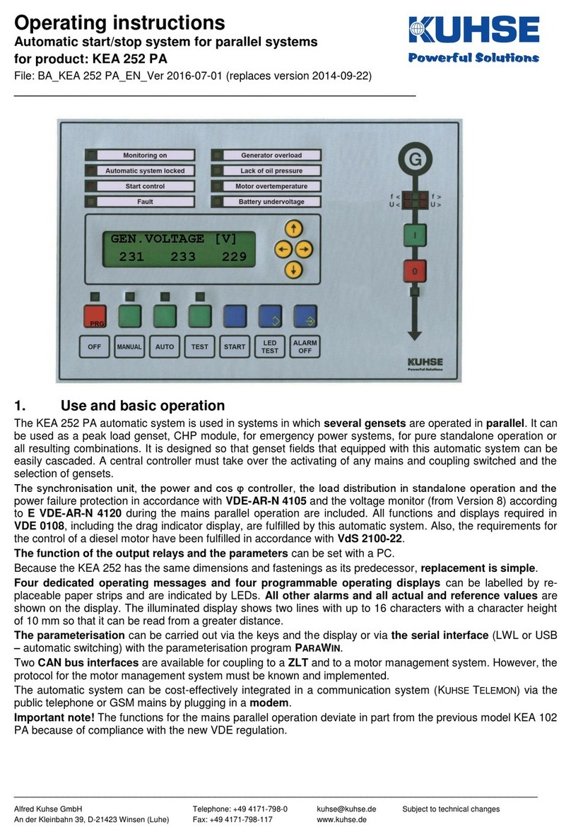
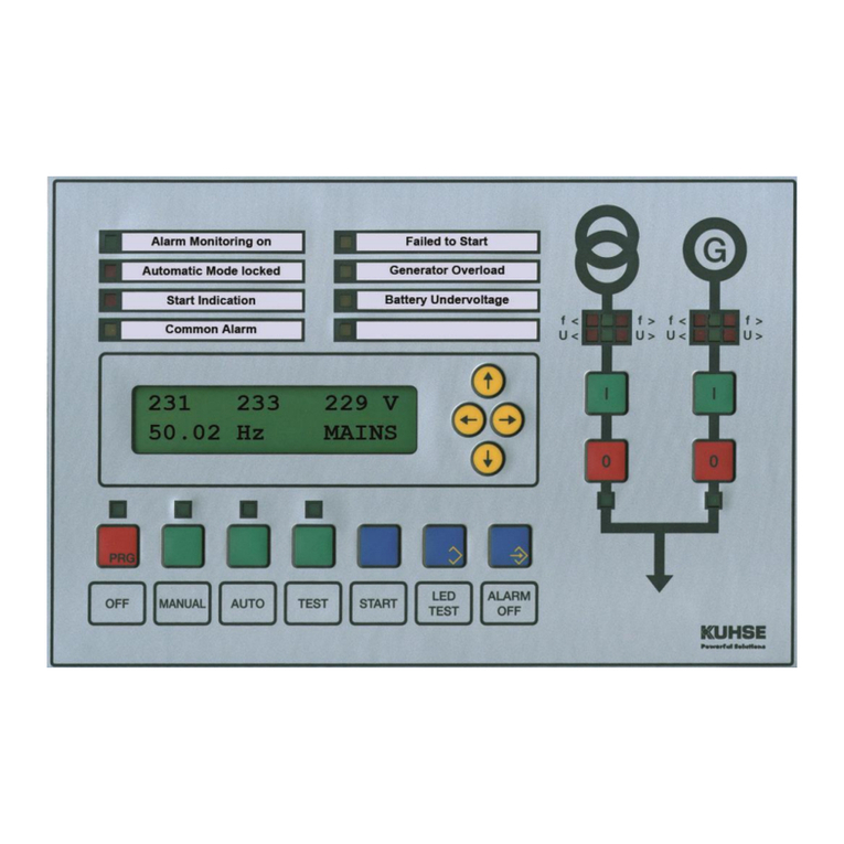
Kuhse KEA 202 INS User manual

______________________________________________________________________________________
Alfred Kuhse GmbH
Telefon: +49 4171-798-0
Technische Änderungen vorbehalten
An der Kleinbahn 39, D-21423 Winsen (Luhe)
Telefax: +49 4171-798-117
www.kuhse.de
Operating instructions
Automatic start/stop system for stand-alone gensets
for product: KEA 202 INS
File: BA_KEA 202 INS_EN_Ver 2016-07-01 (ersetzt Version 2014-09-18)
1. Use and basic operation
The KEA 202 INS automatic system is used in systems which are operated solely as standalone gensets.
Generator current sensor, overload, short-circuit, asymmetric load and the drag indicator display of the current
load are completeley integrated. The automatic control unit uses the RZ-071-D of KEA series 070. The addi-
tional relay unit RZ-071-E can be used as an amplification. Because the KEA 202 has the same dimensions
and fastenings as its predecessor, replacement is simple.
Four dedicated operating messages and four programmable operating displays can be labelled by replaceable
paper strips and are indicated by LEDs. All other alarms and all actual and reference values are shown on the
display. The illuminated display shows two lines with up to 16 characters with a character height of 10 mm so
that it can be read from a greater distance. The parameterisation can be carried out via the keys and the
display or via the serial interface (LWL) with the parameterisation program PARAWIN.
Two CAN bus interfaces are available for coupling to a ZLT and to a motor management system. However,
the protocol for the motor management system must be known and implemented.
The automatic system can be cost-effectively integrated in a communication system (KUHSE TELEMON) via the
public telephone or GSM mains by plugging in a modem.
Important note!
The automatic system can be operated very easily by using the familiar buttons as with all previous models
and without menu navigation.

Operating instructions KEA 202 INS - 2 / 22 - File: BA_KEA 202 INS_EN_Ver 2016-07-01.docx
______________________________________________________________________________________
Alfred Kuhse GmbH
Telefon: +49 4171-798-0
Technische Änderungen vorbehalten
An der Kleinbahn 39, D-21423 Winsen (Luhe)
Telefax: +49 4171-798-117
www.kuhse.de
2. Revision history
Created
Changed
Version
02-04-13
First edition
02-04-13
18/09/2014
Connection diagrams updated. Design and drawing fully renewed
18/09/2014
06/01/2015
Figures renewed for display and control elements
06/01/2015
01/07/2016
Edit new pictures
01/07/2016
3. Content
1. Use and basic operation............................................................................................................................ 1
2. Revision history.......................................................................................................................................... 2
3. Content ...................................................................................................................................................... 2
4. Functions ................................................................................................................................................... 4
5. Warnings.................................................................................................................................................... 4
5.1. Regulations and instructions.............................................................................................................. 4
5.2. Installation and commissioning.......................................................................................................... 4
5.3. Connections....................................................................................................................................... 4
5.4. Battery and supply voltage ................................................................................................................ 4
5.5. Coils................................................................................................................................................... 4
6. Basic operation of automatic system......................................................................................................... 5
6.1. Operation of the display..................................................................................................................... 5
6.2. Display contrast setting...................................................................................................................... 5
6.3. Parameterisation................................................................................................................................ 6
6.3.1. Description................................................................................................................................. 6
6.3.2. General parameters, group 0..................................................................................................... 6
7. Display and control elements..................................................................................................................... 7
7.1. Monitoring on..................................................................................................................................... 7
7.2. Automatic system locked................................................................................................................... 7
7.3. Start control........................................................................................................................................ 7
7.4. Fault................................................................................................................................................... 8
7.5. Four programmable displays ............................................................................................................. 8
7.6. Mimic diagram / Voltage monitor ....................................................................................................... 8
7.7. Keys for operating mode.................................................................................................................... 8
7.8. Start key............................................................................................................................................. 8
7.9. LED Test button................................................................................................................................. 9
7.10. Alarm Off button............................................................................................................................. 9
8. Operating modes ....................................................................................................................................... 9
8.1. Controlling the auxiliary drives........................................................................................................... 9
8.2. Off operating mode............................................................................................................................ 9
8.3. Manual operating mode..................................................................................................................... 9
8.3.1. Description................................................................................................................................. 9
8.3.2. Manual speed adjustment.......................................................................................................... 9
8.3.3. Manual voltage adjustment........................................................................................................ 9
8.4. Auto operating mode ....................................................................................................................... 10
8.4.1. Description............................................................................................................................... 10
8.4.2. External start order .................................................................................................................. 10
8.5. Test operating mode........................................................................................................................ 10
9. Sprinkler operation................................................................................................................................... 10
10. Alarm messages.................................................................................................................................. 11
10.1. Display and acknowledgement of alarms.................................................................................... 12
10.2. Description of the alarms............................................................................................................. 12

Operating instructions KEA 202 INS - 3 / 22 - File: BA_KEA 202 INS_EN_Ver 2016-07-01.docx
______________________________________________________________________________________
Alfred Kuhse GmbH
Telefon: +49 4171-798-0
Technische Änderungen vorbehalten
An der Kleinbahn 39, D-21423 Winsen (Luhe)
Telefax: +49 4171-798-117
www.kuhse.de
10.2.1. Engine does not switch off........................................................................................................12
10.2.2. False start.................................................................................................................................12
10.2.3. Motor fault.................................................................................................................................12
10.2.4. Overspeed................................................................................................................................12
10.2.5. Alarms 13 and 14......................................................................................................................12
10.2.6. Battery voltage monitor.............................................................................................................12
10.2.7. Analogue input alarms..............................................................................................................13
10.2.8. Generator circuit breaker tripped..............................................................................................13
10.2.9. Generator switch-off impeded ..................................................................................................13
10.2.10. Alarms of the voltage monitor...............................................................................................13
10.2.11. Monitoring the flows..............................................................................................................13
10.2.12. Maintenance interval reached ..............................................................................................13
10.2.13. Maintenance interval exceeded............................................................................................13
11. Actual values ........................................................................................................................................14
11.1. Description....................................................................................................................................14
12. Further functions...................................................................................................................................15
12.1. Frequency controller.....................................................................................................................15
12.2. Voltage regulator ..........................................................................................................................15
12.3. Quick stop (Emergency Stop/Emergency Off) .............................................................................15
12.4. Start program................................................................................................................................15
13. Technical data ......................................................................................................................................16
13.1. KEA controller..............................................................................................................................16
13.2. Analogue inputs and outputs........................................................................................................16
13.3. Additional relay unit RZ-071-D .....................................................................................................16
13.4. Additional relay unit RZ-071-E (optional.......................................................................................17
13.5. Serial interfaces............................................................................................................................17
13.6.KNG for coupling to other systems (option) .................................................................................17
14. Thermal overload tripping characteristic curve.....................................................................................18
15. Connection diagrams............................................................................................................................19
15.1. Connection diagram RZ-071-D.....................................................................................................19
15.2. Relay unit RZ-071-E (optional).....................................................................................................20
15.3. Connection diagram KEA 202 INS...............................................................................................20
15.4. Analogue inputs connection .........................................................................................................21
16. Drilling template scale 1:1 –print out without scaling! ........................................................................22

Operating instructions KEA 202 INS - 4 / 22 - File: BA_KEA 202 INS_EN_Ver 2016-07-01.docx
______________________________________________________________________________________
Alfred Kuhse GmbH
Telefon: +49 4171-798-0
Technische Änderungen vorbehalten
An der Kleinbahn 39, D-21423 Winsen (Luhe)
Telefax: +49 4171-798-117
www.kuhse.de
4. Functions
The following functions are implemented:
Start/stop for diesel and gas motor with check of start preconditions,
Generator voltage, frequency and rotating field (asymmetry),
Generator current sensor: Overload, short-circuit, asymmetric load and thermal overload (bimetallic re-
lay),
64 alarm messages, 35 of which are parametrised specific to the customer (text and control) and 6
alarms (alarms 24, 25 und 33-36 ), only the control can be parametrised
Battery monitor and four additional analogue inputs for direct recording of analogue sensors,
Control of two alarms via limit values for each analogue input,
Two potential-free analogue outputs, e.g. for direct control of speed or other controllers,
Parameterisation via LWL or USB interface –with automatic switching –or direct via the keys and the dis-
play,
two CAN bus interfaces for the central control system (ZLT) and for motor management (J1939)
Event memory for 127 messages with real-time display of date and time.
Diverse, reasonably priced expansion options: Modem, pressure control, Profibus coupling, etc.
5. Warnings
5.1. Regulations and instructions
1. Applicable regulations, especially those of the VDE must be observed.
2. The information in the service instructions must be complied with prior to commissioning.
3. The parameterisation of the unit must be carried out in such a way that endangerment of persons and
property is excluded.
5.2. Installation and commissioning
The installation and commissioning must only be carried out by sufficiently qualified personnel.
5.3. Connections
1. The connection of the unit must be carried out carefully, as a wrong connection could lead to the de-
struction of the unit. The connection regulations must be observed!
2. The PE(N) must be connected to the terminal 5 of X403.
3. The shields of the analogue signals must only be connected to the earthing screw next to terminal
strip X401
and otherwise no other connection to metal parts.
4. Converter connections k must be connected to the protective conductor.
5.4. Battery and supply voltage
5. If the battery has to be disconnected, the charging unit must be switched off.
6. The battery negative potential must be earthed at the input terminal on the switchboard. The mini-
mum cross-section is 10 mm2.
7. The supply voltage (12 or 24 V DC) is selected using a switch located on the RZ-071-D.
8. If the supply voltage of the automatic system was switched off, it must only be switched on again after
approx. 20 seconds.
9. The leakage current of the noise filter upon a 2-phase voltage loss is 22 mA.
5.5. Coils
All the coils must be provided with a freewheeling diode (for DC voltage) or with a quench circuit matching
the inductance of the coil. This also applies for all relays and inductances that are used in the switchgear or
are externally activated.

Operating instructions KEA 202 INS - 5 / 22 - File: BA_KEA 202 INS_EN_Ver 2016-07-01.docx
______________________________________________________________________________________
Alfred Kuhse GmbH
Telefon: +49 4171-798-0
Technische Änderungen vorbehalten
An der Kleinbahn 39, D-21423 Winsen (Luhe)
Telefax: +49 4171-798-117
www.kuhse.de
6. Basic operation of automatic system
The automatic system can be operated very easily, as with all previous models and without menu navigation.
The operating mode can be selected using four buttons. In MANUAL and TEST mode, the generator is switched
on and off using the buttons arranged in the mimic diagram.
In MANUAL mode, the START button is programmed for a manual start. The LED TEST and ALARM OFF buttons
are self-explanatory.
During normal operation, the display is only required to display pending alarms and the actual values. The
menu is also easy to use here: Use the [→] and [←] keys to select the required group (alarms or actual val-
ues) and use the [↑] and [↓] keys to display the required actual value or pending alarms.
6.1. Operation of the display
You select a parameter or a value just like you read a book. The different groups are saved as 'pages'. The
groups can be scrolled through forwards and backwards using the [→] and [←] cursor keys. Within a group,
they are read like 'lines' of a text from top to bottom. The lines are selected by pressing the cursor buttons [↓]
(down) and [↑] (up). If the ‘end of the page’ is reached, it starts again from the top or the bottom.
By holding the LED TEST key and pressing the [←] key, the ACTUAL VALUES group is directly selected; by
holding LED TEST and pressing the [→] key, the display of alarms is directly selected.
To change a parameter, first enter the valid ID number. A Group 0 parameter, -GENERAL PARAMETERS-, can
be changed without entering a valid ID number. A parameter is changed as described above.
1. Select the group of the desired parameters with the [←] and [→] buttons.
2. The display with the required parameter is selected using the [↑] or [↓] key. A maximum of two parameters
are displayed.
3. Press the OFF and LED TEST buttons (function PARA ON or PARA OFF) at the same time. The parameteri-
sation mode is initiated and is indicated by the solid cursor [ █ ]. It is no longer possible to change the
group.
4. The required parameter is selected with the [↑] or [↓] key.
5. By simultaneously pressing OFF and ALARM OFF (ENTER function), the displayed line is defined, which is
indicated by the cursor shape that now displays the parameter position to be changed by an underscore [
_]. The line may no longer deselected.
6. The parameter position to be changed is selected using the [←] and [→] cursor buttons and a numeric
parameter is increased or decreased by 1 using the [↑] and [↓] buttons. A parameter that is displayed by a
letter (prefix, alarm coding), is changed using these buttons in reverse order.
7. The displayed parameter is applied by simultaneously pressing Off and Alarm off.
If you want to cancel the parameterisation step, simultaneously press the Off and LED Test buttons instead
of OFF and ALARM OFF.
6.2. Display contrast setting
The display contrast is increased by holding the LED TEST button and pressing the [↑] button (display becomes
darker) or decreased by holding the [↓] button (display becomes brighter).

Operating instructions KEA 202 INS - 6 / 22 - File: BA_KEA 202 INS_EN_Ver 2016-07-01.docx
______________________________________________________________________________________
Alfred Kuhse GmbH
Telefon: +49 4171-798-0
Technische Änderungen vorbehalten
An der Kleinbahn 39, D-21423 Winsen (Luhe)
Telefax: +49 4171-798-117
www.kuhse.de
6.3. Parameterisation
6.3.1. Description
The parameterisation is described in the SERVICE MANUAL. The parameterisation of the basic settings, group
0, is explained in the following. These parameters can be changed without an ID number. Group 0 is se-
lected using the [←] and [→] keys.
6.3.2. General parameters, group 0
The parameters of this group can be changed without a valid ID number.
KEA 202 INS
KUHSE GmbH
90567 ORDER NMR
12345 F-NUMMER
SOFTWARE
010/01.07.14
***** IDENT-NMR
***** PIN NUMMER
BACK LIGHT OFF
120 sec DELAY
SHOW PARAMETERS
+ [+]YES [-]NO
LANGUAGE
0 0=DE, 1=UK
Control unit type is displayed.
Display of the KUHSE order number and the control unit’s production number. This
information is important for later contact with the factory.
Software date and version number.
Input the Ident- and PIN numbers. Parameterisation is described in the Service
Manual.
You do not need to enter a valid Ident-number to modify parameters of this group.
Duration of display illumination. The background illumination is switched on for this
time when any key is pressed. The switch-off delay starts after each last press of a
button. This period can be set in increments of 10 seconds from 10 to 2400 sec-
onds. The light remains on if any alarm is present.
In normal operation it is useful to use the [←] and [→] buttons between the display
of actual values and the current alarm signals. Parameter groups are skipped over
in normal operation if this parameter is set to [-], so only one key strike changes be-
tween ACTUAL VALUES and CURRENT ALARMS.
Enter a [+] if you want to change a parameter to view the parameter groups.
Irrespective of this setting, you can always press LED TEST and [←] to go direct to
ACTUAL VALUES or LED TEST and [→] to CURRENT ALARMS.
All text is available in two languages (e.g. German and English). You can select the
language with this parameter: Enter [0] for German or [1] for English.
03.05.14
12:17:35
Date and time.
The software clock on the control unit has to be set after any power failure. The
control unit is fitted with a battery-buffered hardware clock if events are to be saved
or printed (Option).

Operating instructions KEA 202 INS - 7 / 22 - File: BA_KEA 202 INS_EN_Ver 2016-07-01.docx
______________________________________________________________________________________
Alfred Kuhse GmbH
Telefon: +49 4171-798-0
Technische Änderungen vorbehalten
An der Kleinbahn 39, D-21423 Winsen (Luhe)
Telefax: +49 4171-798-117
www.kuhse.de
7. Display and control elements
Display and control elements:
A1 4 important control elements A2: 4 programmable displays
B1 Generator voltage B2: Generator ON B3: Generator OFF B4: Display Generator ON
C1 Buttons for parameterisation C2: Keys for operating mode C3: Other buttons
D1 Display, illuminated, 2 lines, each with 16 characters, character height 10 mm D2: Cursor keys
Parameterisation
OFF and LED TEST buttons
Function: PARA ON
OFF and Alarm OFF buttons
Function: ENTER
Contrast setting
LED TEST and
↑
buttons
More contrast
LED TEST and
↓
buttons
Less contrast
7.1. Monitoring on
This green display (after the genset start-up) signals the release of the operating-dependent delayed alarms.
As soon as the motor has started up, this display flashes until the monitoring is enabled. The display goes
out at the beginning of the shut-down process.
7.2. Automatic system locked
This red display illuminates if an alarm to be switched off has elapsed or the external quick stop was actu-
ated. In order to unlock the system, the Off operating mode must be selected. If the signal cannot be cleared
even in Off, the external quick stop is still active.
7.3. Start control
The message will be activated as soon as a start request is present in automatic mode or if manual or test
mode has been selected. The display flashes as long as there is no start release. The display goes out as
soon as the genset exceeds the ignition speed during start-up (recognised from the D+ signal of the genera-
tor or from the revolution transmitter signal). Switching on the starter is then inhibited, even if attempted man-
ually. The starting generator voltage interrupts the start but does not cause the start control indicator to extin-
guish.

Operating instructions KEA 202 INS - 8 / 22 - File: BA_KEA 202 INS_EN_Ver 2016-07-01.docx
______________________________________________________________________________________
Alfred Kuhse GmbH
Telefon: +49 4171-798-0
Technische Änderungen vorbehalten
An der Kleinbahn 39, D-21423 Winsen (Luhe)
Telefax: +49 4171-798-117
www.kuhse.de
7.4. Fault
This yellow indicator flashes and the horn sounds once a new alarm occurs. Only the horn signal is acknowl-
edged using the Alarm Off key. The display automatically shows the page with the actual alarms.
If there are multiple alarms pending at the same time, the alarm to be acknowledged is selected using the [↑]
and [↓] cursor keys. For identification purposes, 'New' at the start of the line stands for an unacknowledged
or 'ACKN' for an already acknowledged alarm.
The yellow indicator lights up permanently once all alarms are acknowledged and goes out after all alarms
are cleared.
7.5. Four programmable displays
The functions of the four indicators of the right row are programmable within broad limits. You can display
selected, important alarms or used them as operating messages. Despite the direct display, alarms are also
shown on the display.
In addition, each of the 29 digital inputs can be used as an input for an parametrised operating message.
7.6. Mimic diagram / Voltage monitor
The mimic diagram displays the generator and the busbar. The position of the generator circuit breaker is
indicated through the green display underneath the keys. Four red and two green indicators are provided for
monitoring the generator voltage. They show whether the voltage is in the nominal range or whether and
which deviations are present. These indicators arranged under the generator symbol signal:
f <
f >
U <
U >
The green indicators signal that the monitored functions of voltage and frequency are within the tolerances.
The red LEDs only indicate a voltage error if the respective function is enabled for monitoring
All functions (U<, U>, f<, f>) and the response values of the voltage monitors can be parametrised. The UN-
DERVOLTAGE display also appears if the measuring voltage is connected with a left rotation field or if the volt-
age has too large an asymmetry of the vectors.
If an enabled monitoring signals a deviation from the nominal range, the respective red indicator flashes.
Both green indicators remain switched on for the duration of the drop-out delay of the monitor output. After
the delay expires, they go out and the red indicator illuminates continuously. The function is now processed
internally.
As soon as the voltage and frequency values are within the tolerance range again, the red display goes out
immediately and a release delay time is started. During this time, both green indicators flash that start illumi-
nating continuously when the time has expired. The voltage is then recognised internally as ‘good’.
The indicators are switched off if the OFF operating mode is selected or if there is no start command pending
in automatic operation.
Tasten für Betriebsart
Durch Betätigen der Tasten OFF, MANUAL, AUTO oder TEST wird die entsprechende Betriebsart angewählt. Die
Umwahl kann (über einen Eingang am Relaiszusatz) durch einen Schlüsselschalter blockiert sein.
Die Drehzahl kann in den Betriebsarten MANUEL und TEST von Hand eingestellt werden. Dazu ist unter IST-
WERTE die Drehzahl anzuzeigen und die Taste MANUEL bzw. TEST gedrückt zu halten. Mit den Cursortasten
[↑] bzw. [↓] kann dann das Drehzahlsignal zur Maschine angehoben bzw. abgesenkt werden.
7.7. Keys for operating mode
The respective operating mode is selected by actuating the OFF, MANUAL, AUTO or TEST keys. The selection
can be blocked by a key switch (via an input on the additional relay unit).
The speed can be manually set in the MANUAL and TEST operating modes. To do so, the generator voltage
must be displayed under ACTUAL VALUES and the MANUAL or TEST key must be kept pressed. The speed signal
for the machine can be increased or decreased with the[↑] or [↓] cursor keys.
7.8. Start key
The motor can be started in manualoperating mode by actuating this button. If the start program for a gas
motor is parametrised, the start sequence is processed accordingly. If the motor needs to be preheated, the
pre-heating device must be externally controlled. Actuating this key is ineffective when the machine is run-
ning or also in any other selected operating mode.

Operating instructions KEA 202 INS - 9 / 22 - File: BA_KEA 202 INS_EN_Ver 2016-07-01.docx
______________________________________________________________________________________
Alfred Kuhse GmbH
Telefon: +49 4171-798-0
Technische Änderungen vorbehalten
An der Kleinbahn 39, D-21423 Winsen (Luhe)
Telefax: +49 4171-798-117
www.kuhse.de
7.9. LED Test button
The functioning of all LEDs of the automatic system can be tested by this button. It is also used as a multi-
function button when parametrising and for the contrast setting.
7.10. Alarm Off button
An actuation pulse from this key is used to switch off the acoustic signal issued by a new alarm. If you press
it a second time, the alarm is deleted if the alarm-triggering event is no longer pending. Additional functions
are described in the alarm messages document.
8. Operating modes
The operating modes are selected by four keys. The selected operating mode is signalled by the LED above
the key. The keys can be electrically locked by an input (e.g. by connection of an external key-operated con-
trol switch) so any unauthorised or random change of a defined operating mode is prevented. The operating
modes described below can be selected using the keys.
8.1. Controlling the auxiliary drives
Before each start (if parameterised), a relay with the Auxiliary drives on function picks up. The Start Control
indicator flashes. If the start is released (e.g. gas tightness is checked, exhaust flap open, lubricating pres-
sure is reached), feedback must be provided. The flashing Start Control indicator lights up permanently after
the start release is issued (when the machine is at a standstill) and the engine can be started.
If no start release is required, the input must be permanently connected with the negative potential.
as otherwise no start is carried out.
8.2. Off operating mode
The Off position is automatically selected (reset function) during the application of battery voltage in order to
prevent the triggering of an unintentional start-up. When switching to Off from another operating mode:
a genset operation is immediately ended
Previously displayed alarms, except fault messages 13 and 14, are deleted as long as the respective
alarm contact is still active
The automatic system is unlocked, even if there is no signal on the quick stop input (emergency stop).
8.3. Manual operating mode
8.3.1. Description
After selecting the MANUALoperating mode, any auxiliary drives are switched on and, after start enable car-
ried out, the motor can be started with the START key. If the generator voltage is within the parametrised
nominal values and no alarm that switches off the generator is pending, genset operation can be switched to
with the Gen. On key (I). The generator is switched off after actuating the Gen. Off key (O).
The actuation of the On key remains ineffective if the generator voltage does not lie within the specified lim-
its. An external start order does not lead to the automatic switch-on of the generator.
In order to switch off the genset, the Off or (if the automatic start is not present) Automatic operating mode
must be selected.
8.3.2. Manual speed adjustment
The speed can be manually set in the MANUAL and TEST operating modes. To do so, the generator voltage
must be displayed under ACTUAL VALUES and the MANUAL or TEST key must be kept pressed. The speed sig-
nal for the machine can be increased or decreased with the [ ↑ ] or [ ↓ ] cursor keys.
8.3.3. Manual voltage adjustment
The voltage can be set manually. To do so, the generator voltage must be displayed under actual values and
the Manual or Test key must be kept pressed. The control voltage for the generator voltage controller can be
increased or decreased with the [ ↑ ] or [ ↓ ] cursor keys.

Operating instructions KEA 202 INS - 10 / 22 - File: BA_KEA 202 INS_EN_Ver 2016-07-01.docx
______________________________________________________________________________________
Alfred Kuhse GmbH
Telefon: +49 4171-798-0
Technische Änderungen vorbehalten
An der Kleinbahn 39, D-21423 Winsen (Luhe)
Telefax: +49 4171-798-117
www.kuhse.de
8.4. Auto operating mode
8.4.1. Description
For an automatic start (using the remote start command ), any auxiliary drives are switched on and the para-
metrised start program is triggered after the start function is enabled. If the genset has not started at the end
of the start program, the failed start alarm is issued and the automatic system inhibited.
After the genset has started up, the generator is switched on as soon as the nominal generator voltage and
frequency are reached.
After removing the start command, the delay time is switched (switch-off delay). The generator is switched
off then. To avoid heat accumulation, the genset switches the generator off, continues to run without load for
the set run-on time and is then shut down.
8.4.2. External start order
The start can be enabled using two remote start commands :
Start with switching (remote start WITH load transfer) (terminal 18)
Start without switching (remote start WITHOUT load transfer) (terminal 25)
Sprinkler requirement (terminal 23).
For an automatic start with a generator switch-on, the genset starts up and switches to generator operation.
The generator will be switched off equally after deactivating the remote start.
The Input Start without switching on is provided for e.g. supply voltage sensitive consumers. For providing
e.g. a fast availability for supplying power, the genset can be started via this input. Only the starting program
runs down, no generator connection takes place. If a remote starting command with generator switch-on is
given, generator connection takes place.
8.5. Test operating mode
After selecting the test position, any auxiliary drives are switched on and the parametrised start program is
triggered after the start function is enabled. If the generator voltage with its voltage and frequency values are
within the nominal ranges, generator operation can be switched on using the GEN.-ON(I) key resp. switched
off using the GEN.-AUS (O)arranged in the mimic diagram.
If a remote start command with switching occurs during test operation, the system switches to generator op-
eration. In these cases, it is no longer possible to switch off the generator circuit breaker manually.
In order to switch off the genset, the Off or (if the automatic start is not present) Automatic operating mode
must be selected.
9. Sprinkler operation
The following functions are intended for the operation of an electrical sprinkler pump:
Switching over of all alarms to be switched off to warning
Start program with 10 (parametrisable) start attempts
for the duration of the start-up time of the sprinkler pump in accordance with the parameterisation switch-
off of the emergency power consumers or no interruption of the emergency supply.
For ending the sprinkler requirements in accordance with the parameterisation:
Cancellation of sprinkler operation after the SPRINKLER RUN-ON TIME or only manually switched off
The time stage for sprinkler operation run-on time can be set in the range 10 to 2400 seconds. If it is para-
metrised to 0 sec., the genset does not automatically switch off.
In this case, the display of the Off operating mode flashes.
The genset can then only be stopped by the quick stop or Off operating mode.
The interruption of the emergency current operation for the switching on of the sprinkler pump can be para-
metrised in the range 0 to 24 sec. For the 0 sec. setting, there is no switching-off of the consumers. The
switching-off of the consumers begins with the sprinkler operation signal.
If the sprinkler requirement is met, the emergency power consumers are also switched on during a power
failure or remote start. For return of the power or after removal of the remote start command, the emergency
power consumers are switched back to the mains after the switch-back delay.
Switching off the generator or shutting it down due to an alarm is suppressed. However, if a switch-off alarm
occurs, the collective switch-off alarm is output.

Operating instructions KEA 202 INS - 11 / 22 - File: BA_KEA 202 INS_EN_Ver 2016-07-01.docx
______________________________________________________________________________________
Alfred Kuhse GmbH
Telefon: +49 4171-798-0
Technische Änderungen vorbehalten
An der Kleinbahn 39, D-21423 Winsen (Luhe)
Telefax: +49 4171-798-117
www.kuhse.de
10. Alarm messages
The automatic system can process 64 alarms. Alarms 1 - 19 and 49 –64 are variable from the text and from
the resolution, i.e. the texts and control of these alarms were specified with the PARAWIN parameterisation
program. They are controlled by contact inputs (connections 1 to 14 unused inputs of the additional relay
unit) or by internal flags (controller impeded, analogue channel limit value too high, etc.). The parameterisa-
tion is described in the service manual. Because of the parameterisation, deviations from the following de-
scription can exist.
The alarms are basically divided into three groups:
Alarms that are only monitored delayed after start-up of the motor (e.g. low oil pressure). The release can
be recognised on the green 'monitoring On' display.
Alarms that are also monitored when the motor stops (e.g. battery undervoltage), except in the Off operat-
ing mode. They are designated as without delay.
The alarm messages 13 and 14 are always monitored, even in the Off operating mode. They are used for
messages (e.g. leaks). The horn is not switched on in the Off operating mode, but the alarms are not in-
cluded in the collective alarm. They behave like normal alarms if an active operating mode (so not Off) is
selected.
The alarms are configured as follows:
Alarm is active or locked
Contact is in standby current or operating current,
Delayed or undelayed monitoring
Warning or switching-off function
In addition for warning alarms: With or without generator switch-off and with Stop after run-on time gener-
ator switch-off in automatic operation.
If the generator is switched off due to a warning alarm in automatic operation, the engine is stopped after the
idle time and the automatic system is locked.
For contact inputs, the respective alarm is triggered with the closing (operating current circuit) or with the
opening (standby current circuit) of the signal contact against negative potential, and for analogue signals, with
the exceeding or falling below of the set limit values. Alarms 11 to 14 can also be parametrised as a failsafe
signal on output relays, i.e. the respective relay attracts if the alarm is not pending.

Operating instructions KEA 202 INS - 12 / 22 - File: BA_KEA 202 INS_EN_Ver 2016-07-01.docx
______________________________________________________________________________________
Alfred Kuhse GmbH
Telefon: +49 4171-798-0
Technische Änderungen vorbehalten
An der Kleinbahn 39, D-21423 Winsen (Luhe)
Telefax: +49 4171-798-117
www.kuhse.de
10.1. Display and acknowledgement of alarms
If there is no new actual pending, the Actual Alarms group is selected with the [→] and [←] buttons or by
simultaneously pressing LED TEST and [←] button.
When a new alarm occurs, the FAULT♠ indicator flashes (yellow indicator in the left row of the panel). At the
same time, the acoustic signal is switched on. The horn is switched off and the display is automatically
switched to the page with the pending alarms using the ALARM OFF button.
Either <NEW> for unacknowledged alarms or <ACKN> for acknowledged alarms comes before the text of
the pending alarm.
Unacknowledged alarm Acknowledged alarm Display without pending alarms
The displayed alarm is acknowledged or if the fault cause is remedied, an already acknowledged alarm is
deleted by pressing the ALARM OFF button. If all alarms are acknowledged, the Common Alarm indicator lights
up permanently. It starts flashing again with a new alarm. If all alarms are deleted, the common alarm indicator
is switched off. The pending alarms are displayed successively and can be acknowledged or deleted using the
[↑] and [↓] buttons.
From the next page (accessible by pressing the [→] button), all pending alarms are displayed successively in
one second intervals. Alarms can no longer be acknowledged or deleted here
If no alarms are pending, the note -No alarms present- is displayed when opening the pages.
10.2. Description of the alarms
10.2.1. Engine does not switch off
If the running message of the motor is still pending after the stop time expires, the Motor does not come to a
standstill alarm is activated. This indicates that the stop equipment (e.g. burned stopping solenoid, jam-
ming gas solenoid valve) of the motor is defective.
10.2.2. False start
The alarm is activated if the genset has not started at the end of the start program. The automatic sys-
tem is locked for any further automatic start-up.
10.2.3. Motor fault
The alarm starts up if the motor is already running and is brought to a standstill without a stop com-
mand. The automatic system is locked at the same time.
10.2.4. Overspeed
For the overspeed monitoring, either the generator frequency or the frequency of a pick-up is used. If
the generator frequency is used for detecting the overspeed, the Generator undervoltage alarm must be par-
ametrised as an alarm to be switched off in order to ensure the protection of the machine, even in the event
of generator voltage failure
10.2.5. Alarms 13 and 14
Both these alarms are delayed by 0 to 240 sec. by the signal transmission, i.e. for the alarm contact to
issue an error, the signal must be pending for a parametrised time. Furthermore, both these alarms are
also effective in the Off operating mode (Off), but without switching on the horn. This means criteria (such
as tank overfilling, leakage warning) that must always be signalled can be monitored.
10.2.6. Battery voltage monitor
On the direct monitoring output, a relay can be parameterised (at standby current) such that the message is
passed on with standby current even when in Off operating mode.
NEW GENERATOR
OVERLOAD
ACKN GENERATOR
OVERLOAD
NO ALARMS
PRESENT

Operating instructions KEA 202 INS - 13 / 22 - File: BA_KEA 202 INS_EN_Ver 2016-07-01.docx
______________________________________________________________________________________
Alfred Kuhse GmbH
Telefon: +49 4171-798-0
Technische Änderungen vorbehalten
An der Kleinbahn 39, D-21423 Winsen (Luhe)
Telefax: +49 4171-798-117
www.kuhse.de
10.2.7. Analogue input alarms
Both analogue inputs are equipped with modules for sensors by VDO (motor temperature and oil pres-
sure). For each analogue value, two threshold values can be parametrised, which trigger an alarm if the
value is exceeded or fallen below.
10.2.8. Generator circuit breaker tripped
If parametrised, the generator circuit breaker is monitored for self-activated switch-off (e.g. by attached
overcurrent trigger). The alarm is internally controlled if no generator feedback occurs after the Generator is
on switch-on pulse has expired.
10.2.9. Generator switch-off impeded
The alarm is given if no Generator is off feedback is registered approx. 2 seconds after the switch-off com-
mand for the generator circuit breaker. The genset receives a repeated start command and switches to
generator operation.
If a switch-off alarm now occurs, the genset is shut down and an additional coupling switch can be
switched off via an output to be parametrised.
10.2.10. Alarms of the voltage monitor
The frequency and voltage deviations of the generator can be displayed as error messages. An alarm
does not affect the voltage monitor output. If the GEN. UNDERFREQUENCY alarm, for example, has been
activated as a warning message but the frequency is back in the window, this message remains. However,
the generator voltage is recognised as ‘good’ for the control process in the automatic system.
10.2.11. Monitoring the flows
If required, the generator currents can be monitored for
overcurrent (e.g. 110%)
short-circuit (e.g. 300%)
unbalanced load and
thermal overload (bimetallic relay).
The tripping characteristic curve of a bimetallic relay is recreated for thermal monitoring. The Ther-
mal_overload_tripping_characteristic_curve is displayed further below.
10.2.12. Maintenance interval reached
The remaining time to the next maintenance is displayed under ACTUAL VALUES.If the remaining time has
expired, a warning alarm is triggered. During the maintenance, the interval is set to the number of oper-
ating hours until the next maintenance.
10.2.13. Maintenance interval exceeded
After the remaining time has expired, a rest period duration until the next maintenance is given during
which the maintenance must be carried out. If this time has expired, another alarm is triggered.
This alarm can only be deleted by the maintenance company.

Operating instructions KEA 202 INS - 14 / 22 - File: BA_KEA 202 INS_EN_Ver 2016-07-01.docx
______________________________________________________________________________________
Alfred Kuhse GmbH
Telefon: +49 4171-798-0
Technische Änderungen vorbehalten
An der Kleinbahn 39, D-21423 Winsen (Luhe)
Telefax: +49 4171-798-117
www.kuhse.de
11. Actual values
11.1. Description
The ACTUAL VALUES group is selected with the [→] and [←] buttons or by simultaneously pressing LED TEST
and [←] button. The displays listed below are displayed using the [↓] and [↑] keys. The [↓] button selects the
examples in the order listed below. Symbolically, they are read from top to bottom like the lines of a book
page with the [↓] key, or from bottom to top with the [↑] key. If the ‘end of the page’ is reached, it starts again
from the top or the bottom.
2
231 230 229 V
50.02 Hz GEN.
Display of the generator voltage in the order L1, L2 and L3 and gener-
ator frequency.
3
GEN. CURRENT [A]
742 748 740
Generator flows in the sequence L1, L2 and L3.
4
+ 512 kVA GEN.
+ 445 kW 0.87 in
Display of apparent generator power, performance and middle cos φ.
5
GEN. CURRENT [A]
740 730 735
Display of the drag indicator ammeter. The display is reset by press-
ing the ALARM OFF key for approx. 5 seconds.
6
98 % GEN. LOAD
3 % ASYMMETRIC LOAD
Power load of the generator for THERMAL OVERLOAD ALARM.
Maximum asymmetric load of the three generator flows.
7
BATTERY
26.6 V VOLTAGE
Display of the battery voltage. The measuring signal must be on ter-
minal 1 of X403.
8
SPEED
1500 rpm
Display of the speed. Either the frequency signal of a pick-up is used
or the generator frequency is converted into a speed.
9
000010 STARTS
000103 h OPERATION
6-digit start counter. Setting the counters under OTHER PARAMETERS. *)
6-digit operating hours counter.
10
Operating time
298 h OPERATION
Runtime until the next maintenance.
11
DAILY RUNTIME
010:25 h:m
Resettable short time counter. The counter can be reset to 00:00
here.
12
5.6 bar
oil pressure
example of the analogue display of analogue output channel 1 The
text can be entered with ParaWin.
13
98 DEGREES COOLING
WATER TEMPERATURE
example of the analogue display of analogue output channel 2 The
text can be entered with ParaWin.
14
CHANNEL 3
NOT USED
example of the analogue display of analogue output channel 3 The
text can be entered with ParaWin.
15
CHANNEL 4
NOT USED
example of the analogue display of analogue output channel 4 The
text can be entered with ParaWin.
16
+ 3400 CHANNEL 5
SPEED CONTROLLER
example of the displayed value of analogue output channel 5 The text
can be entered with ParaWin.
17
CHANNEL 6
NOT USED
example of the displayed value of analogue output channel 6 The text
can be entered with ParaWin.

Operating instructions KEA 202 INS - 15 / 22 - File: BA_KEA 202 INS_EN_Ver 2016-07-01.docx
______________________________________________________________________________________
Alfred Kuhse GmbH
Telefon: +49 4171-798-0
Technische Änderungen vorbehalten
An der Kleinbahn 39, D-21423 Winsen (Luhe)
Telefax: +49 4171-798-117
www.kuhse.de
Display 10: Runtime until the next maintenance.
The operating hours counter until the next maintenance is decremented from a maximum value. If the coun-
ter reading reaches 000000, an alarm is triggered (if parametrised). A grace period during which the mainte-
nance must be carried out can be parametrised. The runtime counter UNTIL THE MAINTENANCE now shows
negative operating hours. If no maintenance has been carried out even after the grace period has expired,
another alarm can be activated.
If the grace period is set to 000000, the counter does run into the negative range. It can be set on the dis-
play. Thus, the MAINTENANCE INTERVAL REACHED alarm is deleted.
If a grace period of > 0 is entered (e.g. during the guarantee period), the counter can only be set by the sup-
plier and only withPARAWIN. Therefore, the MAINTENANCE INTERVAL and ALARMS can only be deleted by au-
thorised persons.
Display 11: Daily runtime
Here, the operating hours are counted up to 999 hours and 59 minutes. It is used for recording short
runtimes (e.g. during trial operations or mains failures). It can be set to 00:00 without the main operating
hours counter being changed.
12. Further functions
12.1. Frequency controller
The automatic system issues commands for the speed controller if the function is enabled if the frequency is
not within the parametrised window. A break is taken between two commands in order for the motor to have
time to carry out the order.
12.2. Voltage regulator
The automatic system issues commands for the generator voltage controller if the function is enabled and if
the voltage is not within the parametrised window. A break is taken between two commands in order for the
generator voltage control to settle.
12.3. Quick stop (Emergency Stop/Emergency Off)
The input can optionally be activated with an NC or NO contact. A pulse actuation is sufficient to trigger this
function. Thus, independent of the operating mode,
the generator is switched off,
the genset is shut down
and the automatic system is locked for further start processes (display: Automatic system locked).
12.4. Start program
The standard process for gas motors is as follows:
10.Starter on:
11.if the starter speed is exceeded, the ignition is switched on (e.g. 2 sec.),
12.then (approx. 2 sec.) solenoid valve open,
13.starter now on for 7 seconds
14.then close gas solenoid valve,
15.starter off,
16.ignition off after 6 sec.,
17.new start sequence after 1 sec.

Operating instructions KEA 202 INS - 16 / 22 - File: BA_KEA 202 INS_EN_Ver 2016-07-01.docx
______________________________________________________________________________________
Alfred Kuhse GmbH
Telefon: +49 4171-798-0
Technische Änderungen vorbehalten
An der Kleinbahn 39, D-21423 Winsen (Luhe)
Telefax: +49 4171-798-117
www.kuhse.de
The start process for diesel motors is parametrised as follows:
18. Start delay 2 sec.,
19.Starter on for 10 sec.,
20.Pause 7 sec.,
21.3 start attempts,
22.delay MONITORING ON 7 sec.,
23.switch-back delay 60 sec.,
24.run-on time 180 secs.,
25.stop time 30 secs.
If a diesel motor is used with a preheating system, an external preheating button must be provided in the
Manual operating mode. The start delay serves as a preheating time during automatic starts.
13. Technical data
13.1.KEA controller
Unit for front installation, dimensions: (,, depth) 260 x 170 x 100 mm.
Weight approx. 2.2 kg, any installation position, protection rating (installed) IP 44.
Ambient temperature: Storage -20°C ... +70°C, operation 0°C ... +55°C.
Switchable supply voltage 9-12-15V or 14-24-35V DC.
3 parametrisable relays, 35 V DC, 1 Amp. (e.g. for acoustic transducer).
Standards/regulations VDE 100, part 710.
13.2.Analogue inputs and outputs
Gnerator voltage monitor 3-phase, adjustable in 1-Volt steps. With incorrect rotation field, display <U.
Unom. 230/400 Volt, adjustable 50 - 300 Volt. . Class accuracy 1.
Generator frequency monitor 50 or 60 Hz, continuously adjustable from 40 to 70 Hz.
Generator current measurement 3-phase. Class accuracy 1.
Inom. 5 A: Measuring range 0.1 –15 Amp., adjustable in 20 mA steps.
Battery voltage monitor.
Input for pick-up.
Four free analogue inputs can be optionally equipped with interface cards for
PT 100/PT1000,
Current loops,
0 - 10 V DC,
Thermocouple NiCr-Ni,
Temperature and pressure: Encoder from VDO,
Battery charging circuit*.
Two analogue outputs, can be optionally equipped with output cards for 0 –20 mA resp. 0 –10 Volt.
13.3.Additional relay unit RZ-071-D
Device for clipping onto top-hat rails, dimensions: (,, depth) 300 x 100 x 90 mm (with multipoint con-
nector)
Weight approx. 0.7 kg, any installation position, protection rating IP 00.
equipped with:
o Input for generator D+ with pre-excitation for AC generators,
o 14 connections for alarm contacts,
o 14 general control inputs,
o 12 relays, of which 8 can be parametrised,
contact loading: 2 relays max. 35 Volt, 20 Amp. DC,
10 relays, 250 V AC, 6 Amp.

Operating instructions KEA 202 INS - 17 / 22 - File: BA_KEA 202 INS_EN_Ver 2016-07-01.docx
______________________________________________________________________________________
Alfred Kuhse GmbH
Telefon: +49 4171-798-0
Technische Änderungen vorbehalten
An der Kleinbahn 39, D-21423 Winsen (Luhe)
Telefax: +49 4171-798-117
www.kuhse.de
13.4.Additional relay unit RZ-071-E (optional
Device for clipping onto top-hat rails, dimensions: (,, depth) 210 x 100 x 50 mm.
Weight approx. 0.5 kg, any installation position, protection rating IP 00.
equipped with 15 relays, of which 14 can be parametrised, contact loading max. 250 V AC, 6 Amp.
13.5.Serial interfaces
LWL or USB interface –with atic switching –for parameterisation
CAN bus interface to a central control system (ZLT)
CAN bus interface to the motor management (the protocol must be known and implemented).
13.6.KNG for coupling to other systems (option)
Device for clipping onto top-hat rails: KNG (Kuhse Network Gateway) for coupling to other systems via
PROFIBUS DP or Modbus RTU

Operating instructions KEA 202 INS - 18 / 22 - File: BA_KEA 202 INS_EN_Ver 2016-07-01.docx
______________________________________________________________________________________
Alfred Kuhse GmbH
Telefon: +49 4171-798-0
Technische Änderungen vorbehalten
An der Kleinbahn 39, D-21423 Winsen (Luhe)
Telefax: +49 4171-798-117
www.kuhse.de
14. Thermal overload tripping characteristic curve

Operating instructions KEA 202 INS - 19 / 22 - File: BA_KEA 202 INS_EN_Ver 2016-07-01.docx
______________________________________________________________________________________
Alfred Kuhse GmbH
Telefon: +49 4171-798-0
Technische Änderungen vorbehalten
An der Kleinbahn 39, D-21423 Winsen (Luhe)
Telefax: +49 4171-798-117
www.kuhse.de
15. Connection diagrams
15.1. Connection diagram RZ-071-D

Operating instructions KEA 202 INS - 20 / 22 - File: BA_KEA 202 INS_EN_Ver 2016-07-01.docx
______________________________________________________________________________________
Alfred Kuhse GmbH
Telefon: +49 4171-798-0
Technische Änderungen vorbehalten
An der Kleinbahn 39, D-21423 Winsen (Luhe)
Telefax: +49 4171-798-117
www.kuhse.de
15.2. Relay unit RZ-071-E (optional)
15.3. Connection diagram KEA 202 INS
Table of contents
Other Kuhse Control System manuals