manuals.online logo
Brands
  1. Home
  2. •
  3. Brands
  4. •
  5. HEIDENHAIN
  6. •
  7. Control System
  8. •
  9. HEIDENHAIN ECN 413 2C User manual

HEIDENHAIN ECN 413 2C User manual

5/2013
Montageanleitung
Mounting Instructions
Instructions de montage
Istruzioni di montaggio
Instrucciones de montaje
ECN 413 I2C
EQN 425 I2C
WELLA1: 68R
K PPA1: 06, 14
ANELA1: 03I12
BELEA1: 71
PTB 08 ATEX 1094 X
II 2
G Ex
db
IIC T 120 °C
II 2 D Ex tb IIIC T 120 °C
Drehgeber für explosionsgefährdete Bereiche (ATEX).
Rotary encoders for potentially explosive atmospheres (ATEX .
Capteur rotatif pour les zones à risque dexplosion (ATEX).
Encoder per ambienti potenzialmente esposivi (ATEX .
Generador rotativo de impulsos para ámbitos con peligro de
explosión (ATEX).
Page
3 Warnings
10 Items supplied
12 Mounting Dimensions/Assembly
20 Specifications
22 Pin Layout
Maß in mm
Dimensions in mm
Cot s n mm
Dimensioni in mm
Dim nsion s n mm
Inhalt
Contents
Sommair
Indice
Indic
S it
3 Warnhinweise
10 Lieferumfang
12 Anbaumaße/Montage
20 Technische Kennwerte
22 Anschlussbelegung
Pag
3 Recommandations
10 Objet de la fourniture
12 Cote d'encombrement/Montage
20 Caractéristiques techniques
22 Raccordements
Pagina
3 Avvertenze
10 Standard di fornitura
12 Dimensioni di montaggio/Montaggio
20 Dati tecnici
22 Piedinatura
Página
3 Advertencias
10 Suministro
12 Medidas para el montaje/Montaje
20 Datos técnicos
22 Tensión de alimentación/Señales de salida
2
Wellendichtring nicht beschädigen bzw. nicht entfernen.
Avoid damage to the shaft sealing ring and do not remove it.
Ne pas endommager ni retirer la garniture d'étanchéité de l'arbre.
Non danneggiare né rimuovere l'anello di tenuta per albero.
No retirar ni dañar el retén del eje.
Messgerät im Servicefall an HEIDENHAIN-Service,Traunreut, senden.
If service is needed, send the encoder to HEIDENHAIN Service, Traunreut.
En cas de panne, retourner le système de mesure au service après-vente HEIDENHAIN,Traunreut.
Per interventi di manutenzione inviare il sistema di misura all'Assistenza HEIDENHAIN, Traunreut.
En caso de averia enviar el aparato a la agencia de servicio HEIDENHAIN,Traunreut.
Kabel in Betrieb fest verlegen (Zugentlastung).
Fix the cable permanently for operation (strain relief .
En fonctionnement, fixer le câble (décharge de traction).
Posare il cavo in modo fisso (fermacavo .
Fijar el cable durante el funcionamiento (descarga de tracción).
Warnhinw is
Warnings
R commandations
Avvertenze
Adv rt ncias
3
4
Warnhinw is
Warnings
R commandations
Avvertenze
Adv rt ncias
Achtung: Die Montage und Inbetriebnahme ist von einer qualifizierten Fachkraft unter Beachtung der
örtlichen Sicherheitsvorschriften vorzunehmen.
Zusätzlich muss der Maschinenhersteller/-konstrukteur die erforderlichen weiteren Angaben zur
Endmontage (z.B. Losdrehsicherung für Schrauben ja/nein) für die jeweilige Anwendung selbst festlegen.
Die Steckverbindung darf nur spannungsfrei verbunden oder gelöst werden.
Die Anlage muss spannungsfrei geschaltet sein!
Note: Mounting and commissioning is to be conducted by a qualified specialist under compliance with
local safety regulations.
In addition to this, the machine manufacturer or designer himself must define the other data required
for final assembly (e.g. anti-rotation lock for screws required or not for the respective application.
Do not engage or disengage any connections while under power.
The system must be disconnected from power.
5
Att ntion: Le montage et la mise en service doivent être assurés par un personnel qualifié dans le
respect des consignes de sécurité locales.
Dautre part, le fabricant/constructeur de la machine doit définir dautres données nécessaires au
montage final (p.ex. sécurité frein de vis oui/non) pour l´application respective.
Le connecteur ne doit être connecté ou déconnecté quhors potentiel.
Léquipement doit être connecté hors potentiel!
Attenzione: Il montaggio e la messa in funzione devono essere eseguite da personale qualifucato nel
rispetto delle norme di sicurezza locali.
Inoltre, il costruttore della macchina deve definire le ulteriori procedure necessarie per completare il
montaggio (ad esempio: sicurezza allentamento viti sì/no di ogni specifica applicazione.
I cavi posso essere collegati o scollegati solo in assenza di tensione.
Limpianto deve essere spento!
At nción: El montaje y la puesta en marcha deben ser realizados por un especialista cualificado, obser
vando las prescripciones locales de seguridad.
Adicionalmente, el fabricante/constructor de la máquina debe determinar él mismo el resto de indicaciones
requeridas para el montaje final para cada aplicación en particular (p.ej., seguro antigiro para tornillos sí/no).
Conectar o desconectar el conector sólo en ausencia de tensión.
¡La instalación debe ser conectada en ausencia de tensión!
6
Warnhinw is
Warnings
R commandations
Avvertenze
Adv rt ncias
*) Das Rücksetzen des Störungssignales erfolgt erst nach Abkühlung des Drehgebers.
The fault-detection signal is not reset until after the rotary encoder has cooled.
La réinitialisation du signal de perturbation ne s'effectue qu'après refroidissement du capteur rotatif.
La cancellazione del segnale di allarme avviene dopo il raffreddamento dell'encoder.
La cancelación de la señal de interferencia sólo sucede tras el enfriamiento del encoder.
UaS = High:
UaS = Low: *
Störungssignal
Fault detection signal
Signal de perturbation
Segnale di malfunzionamento
Señal de avería
UaS:
7
Vorsicht: wenn Temperatur am Thermoschalter (im Geberflansch integriert) > 100° C (± 5 K),
Ausgangssignale weiterhin verfügbar.
Temperatur am Thermoschalter von 110° C (± 5 K) führt zu einem Abschalten der Versorgungsspannung.
Ein Betrieb mit Positionsrückmeldung ist dann nicht mehr möglich.
Attention: If the temperature at the thermal switch (integrated in the encoder flange
exceeds 100 °C (± 5 K , the output signals remain available.
A temperature at the thermo switch of 110° C (± 5 K switches off the supply voltage.
Operation with position feedback is then no longer possible.
Att ntion: si température sur thermocommutateur (intégré dans la bride du capteur) > 100° C (± 5 K),
signaux de sortie restent disponibles.
ne température de 110° C (± 5 K) sur le thermocommutateur provoque une coupure de
la tension d'alimentation. n fonctionnement avec acquittement de position n'est alors plus possible.
Attenzione: se la temperatura dell'interruttore (integrato nella flangia dell'encoder > 100° C (± 5K ,
i segnali in uscita sono ancora disponibili.
Quando la temperatura sull'interruttore raggiunge 110 °C (±5 K , la tensione di alimentazione si spegne.
Non è più possibile il funzionamento con richiamo della posizione.
At nción: si la temperatura en el contacto térmico (integrado en la brida del encoder) > 100º C (± 5 K).
Señales de salida siguen disponibles.
na temperatura de 110º C (± 5 K) en el contacto térmico ocasiona una desconexión de la tensión
de alimentación. En este caso ya no es posible un funcionamiento con respuesta de la posición.
8
Falls die Kabeldurchführung einer möglichen äußeren Belastung ausgesetzt ist, ist die
Schutzkappe s anzubringen. (Richtlinie 94/9/EG Anhang II 1.2.5).
If the cable exit is subject to possible load, mount the protective cover s.
(Directive 94/9/EG Annex II 1.2.5 .
Si le passage du câble est exposé à une éventuelle charge externe, installer le capot de
protection s. (directive 94/9/CE, annexe II 1.2.5).
Qualora il passacavo sia esposto ad una possibile sollecitazione esterna, è necessario
applicare il cappuccio di protezione s. (Direttiva 94/9/EG allegato II 1.2.5 .
En el caso de que la conducción del cable esté expuesta a una solicitación externa, deberá
instalarse la tapa deprotección s. (Directiva 94/9/ E Anexo 1.2.5).
Warnhinw is
Warnings
R commandations
Avvertenze
Adv rt ncias
9
Schutzkappe im Lieferumfang enthalten
Protective cover included in delivery
Capot de protection compris dans la fourniture
Cappuccio di protezione incluso nello standard di fornitura
La tapa de protección figura entre los elementos suministrados
A-A
19
A-A
A-A
s
=
s
50
10
Li f rumfang
Items su lied
Obj t d la fournitur
Standard di fornitura
Suministro
Separat bestellen:
Order separately:
Commander séparément:
Ordinare separatamente:
Pedir por separado:
SW2
ID 350378-03
Montagezubehör
Mounting accessories
Accessoires de montage
Accessori per il montaggio
Accesorios de montaje
ID 680873-01
Bei Bedarf Klemmring separat bestellen:
Clamping ring to be ordered separately if needed
Commander séparément la bague de serrageÊsi nécessaire :
In caso di necessità, ordinare lanello di serraggio a parte:
Si se requiere, pedir por separado el anillo opresor:
11
Li f rumfang
Items su lied
Obj t d la fournitur
Standard di fornitura
Suministro
ID 680873-01
Bei Bedarf Klemmring separat bestellen:
Clamping ring to be ordered separately if needed
Commander séparément la bague de serrageÊsi nécessaire :
In caso di necessità, ordinare lanello di serraggio a parte:
Si se requiere, pedir por separado el anillo opresor:
12
Anbaumaß
Mounting Dimensions
Cot d' ncombr m nt
Dimensioni di montaggio
M didas para l montaj
À
=
Tolerancing ISO 8015
ISO 2768 - m H
¬ 6
Anschlussteil für Erdungs- und Potentialausgleich gemäß DIN EN 60079-0
Connecting part for equipotential grounding and bonding according to DIN EN 60079-0
Borne de mise à la terre et déquilibrage de potentiel selon DIN EN 60079-0
Collegamento per messa a terra e equipotenziale secondo DIN EN 60079-0
Pieza de conexión para el ajuste de la toma de tierra y del voltaje según DIN 60079-0
A
=Lagerung
Bearing
Roulement
Cuscinetto
Rodamiento
13
Kund ns itig Anschlussmaß
Required mating dimensions
Conditions r quis s pour l montag
Dimensioni di collegamento lato cliente
Cotas d montaj r qu ridas
Á
= Montageöffnung zum Betätigen der Klemmschraube
Opening for driving the clamping screw
Ouverture pour accès au serrage de la vis
Foro di servizio per azionamento della vite di serraggio
Obertura de montaje para el accionamiento del tornillo de apriete
ÁÁ
14
Montag
Assembly
Montag
Montaggio
Montaj
1.
Rillenkennzeichnung am Klemmring muss sichtbar sein.
Groove on clamping ring must remain visible.
La rainure sur l'anneau de serrage doit rester visible.
Le scanalature sull'anello di bloccaggio devono rimanere visibili.
La identificación de las ranuras en el anillo de sujeción debe ser visible.
X8
15
2.
Md = 1.1±0.1 Nm
3.
Md = 1.250.2 Nm
SW2
ID 350378-03
16
Anbaumaß
Mounting Dimensions
Cot d' ncombr m nt
Dimensioni di montaggio
M didas para l montaj
À
=
Tolerancing ISO 8015
ISO 2768 - m H
¬ 6
Anschlussteil für Erdungs- und Potentialausgleich gemäß DIN EN 60079-0
Connecting part for equipotential grounding and bonding according to DIN EN 60079-0
Borne de mise à la terre et déquilibrage de potentiel selon DIN EN 60079-0
Collegamento per messa a terra e equipotenziale secondo DIN EN 60079-0
Pieza de conexión para el ajuste de la toma de tierra y del voltaje según DIN 60079-0
17
A
=Lagerung
Bearing
Roulement
Cuscinetto
Rodamiento
Kund ns itig Anschlussmaß
Required mating dimensions
Conditions r quis s pour l montag
Dimensioni di collegamento lato cliente
Cotas d montaj r qu ridas
= Auf Berührungsschutz achten, (EN 60529).
Protect against contact, (EN 60529 .
Veiller à la protection contre les contacts directs, (EN 60529).
Prestare attenzione alla protezione, (EN 60529 .
Tener en cuenta la protección ante contacto, (EN 60529).
Á
Á
18
Montag
Assembly
Montag
Montaggio
Montaj
Rillenkennzeichnung am Klemmring muss sichtbar sein.
Groove on clamping ring must remain visible.
La rainure sur l'anneau de serrage doit rester visible.
Le scanalature sull'anello di bloccaggio devono rimanere visibili.
La identificación de las ranuras en el anillo de sujeción debe ser visible.
Achtung: Verletzungsgefahr durch drehende Teile. Auf Berührungsschutz achten!
Warning: Risk of injury from rotating parts. Protect against contact!
Att ntion: danger de blessures par des pièces en rotation. Prévoir une protection au contact!
Attenzione: pericolo di lesioni da pezzi rotanti. Mettere protezioni per impedire il contatto!
At nción: riesgo de accidente por causa de piezas en rotación. ¡Considerar una protección ante contacto accidental!
X8
19
Md = 1.1
±
0.1 Nm
3.
1.
2.
4x M3
20
 10 m
 10 m
 50 m
T chnisch K nnw rt
S ecifications
Caractéristiqu s t chniqu s
Dati tecnici
Datos técnicos

This manual suits for next models

1

Other HEIDENHAIN Control System manuals
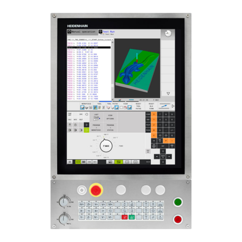
HEIDENHAIN POSITIP 880 User manual

HEIDENHAIN

HEIDENHAIN POSITIP 880 User manual

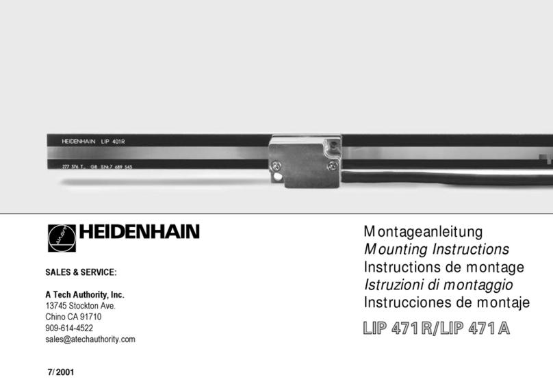
HEIDENHAIN LIP 471R User manual

HEIDENHAIN

HEIDENHAIN LIP 471R User manual

HEIDENHAIN LIF 181 R User manual

HEIDENHAIN

HEIDENHAIN LIF 181 R User manual

HEIDENHAIN TNC 150 B User manual

HEIDENHAIN

HEIDENHAIN TNC 150 B User manual

HEIDENHAIN AK LIC 413 User manual

HEIDENHAIN

HEIDENHAIN AK LIC 413 User manual

HEIDENHAIN ITNC 530 - CONVERSATIONAL PROGRAMMING User manual

HEIDENHAIN

HEIDENHAIN ITNC 530 - CONVERSATIONAL PROGRAMMING User manual

HEIDENHAIN ITNC 530 - CONVERSATIONAL PROGRAMMING User manual

HEIDENHAIN

HEIDENHAIN ITNC 530 - CONVERSATIONAL PROGRAMMING User manual

HEIDENHAIN TNC 407 User manual

HEIDENHAIN

HEIDENHAIN TNC 407 User manual

HEIDENHAIN TNC 370 D Manual

HEIDENHAIN

HEIDENHAIN TNC 370 D Manual

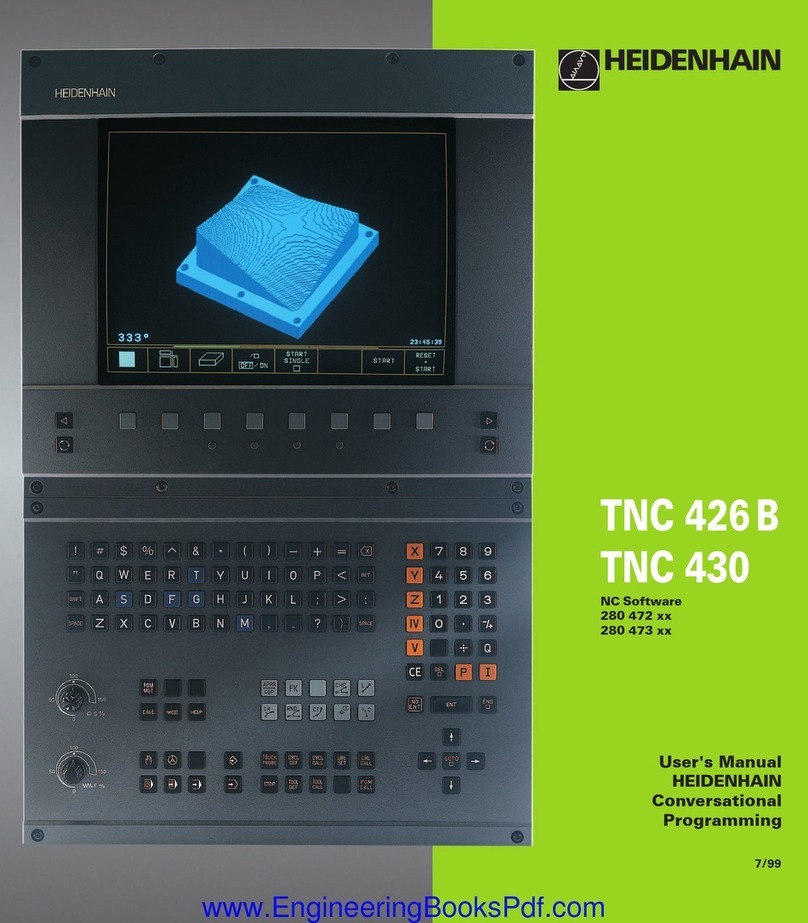
HEIDENHAIN TNC 426 B User manual

HEIDENHAIN

HEIDENHAIN TNC 426 B User manual

HEIDENHAIN MANUALPLUS 620 User manual

HEIDENHAIN

HEIDENHAIN MANUALPLUS 620 User manual

HEIDENHAIN TNC 320 User manual

HEIDENHAIN

HEIDENHAIN TNC 320 User manual

HEIDENHAIN TNC 320 User manual

HEIDENHAIN

HEIDENHAIN TNC 320 User manual

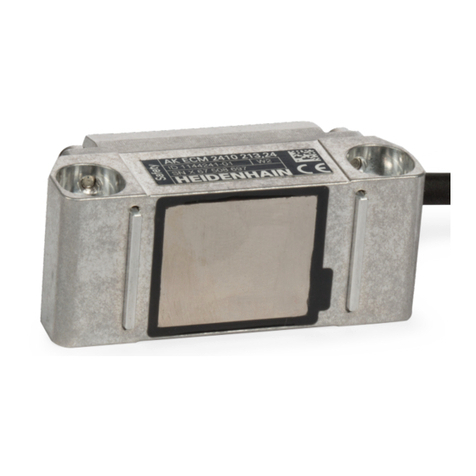
HEIDENHAIN AK ECM 2410 User manual

HEIDENHAIN

HEIDENHAIN AK ECM 2410 User manual

HEIDENHAIN TNC 620 User manual

HEIDENHAIN

HEIDENHAIN TNC 620 User manual
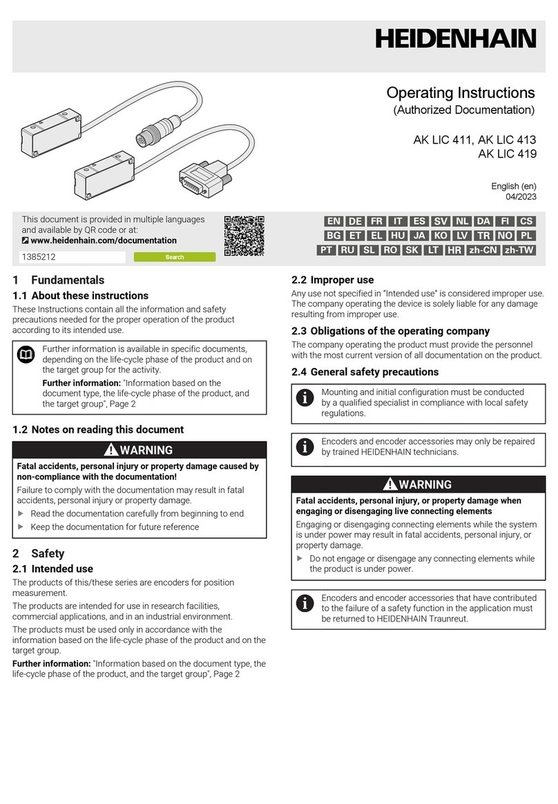
HEIDENHAIN TNC 620 User manual

HEIDENHAIN

HEIDENHAIN TNC 620 User manual

HEIDENHAIN TNC151B Operating instructions

HEIDENHAIN

HEIDENHAIN TNC151B Operating instructions

HEIDENHAIN POSITIP 880 User manual

HEIDENHAIN

HEIDENHAIN POSITIP 880 User manual

HEIDENHAIN ITNC 530 - CONVERSATIONAL PROGRAMMING User manual
HEIDENHAIN

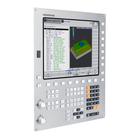
HEIDENHAIN ITNC 530 - CONVERSATIONAL PROGRAMMING User manual

HEIDENHAIN CNC PILOT 640 User manual

HEIDENHAIN

HEIDENHAIN CNC PILOT 640 User manual

HEIDENHAIN TNC 620 Programming Station User manual

HEIDENHAIN

HEIDENHAIN TNC 620 Programming Station User manual

HEIDENHAIN TNC 150 B User manual

HEIDENHAIN

HEIDENHAIN TNC 150 B User manual

HEIDENHAIN TNC 620 User manual

HEIDENHAIN

HEIDENHAIN TNC 620 User manual
HEIDENHAIN iTNC 530 HSCI User manual

HEIDENHAIN

HEIDENHAIN iTNC 530 HSCI User manual
Popular Control System manuals by other brands

TouchTronics POWERTouch P1555 Series Service manual

TouchTronics

TouchTronics POWERTouch P1555 Series Service manual

BFT GIOTTO 30-50 S BT Installation and user manual

BFT

BFT GIOTTO 30-50 S BT Installation and user manual

ABB Relion 615 series List manual

ABB

ABB Relion 615 series List manual

Harvia SENTIO pronet Instructions for installation and use

Harvia

Harvia SENTIO pronet Instructions for installation and use

IntelligentAg RECON SPREADSENSE installation manual

IntelligentAg

IntelligentAg RECON SPREADSENSE installation manual

Altronics PowerQuest manual

Altronics

Altronics PowerQuest manual

welldana B3420 operating instructions

welldana

welldana B3420 operating instructions

SoundOFF bluePRINT ENGND20001 quick start guide

SoundOFF

SoundOFF bluePRINT ENGND20001 quick start guide

Philips dynalite installation guide

Philips

Philips dynalite installation guide

Volvo Penta D3 Operator's manual

Volvo Penta

Volvo Penta D3 Operator's manual

Johnson Controls YORK YLAA0189SE operating instructions

Johnson Controls

Johnson Controls YORK YLAA0189SE operating instructions
Evco EVC80P16N7DSM00 manual

Evco

Evco EVC80P16N7DSM00 manual

RKC INSTRUMENT SR Mini HG Communication instruction manual

RKC INSTRUMENT

RKC INSTRUMENT SR Mini HG Communication instruction manual

Conrad 56 16 00 operating instructions

Conrad

Conrad 56 16 00 operating instructions

Airzone ZBS Quick installation guide

Airzone

Airzone ZBS Quick installation guide

Viessmann SCU345 manual

Viessmann

Viessmann SCU345 manual

Eaton Cutler-Hammer IQ DP-4000 Installation, operation and maintenance instructions

Eaton

Eaton Cutler-Hammer IQ DP-4000 Installation, operation and maintenance instructions

Siemens SIMATIC PCS 7 Function manual

Siemens

Siemens SIMATIC PCS 7 Function manual

manuals.online logo
manuals.online logoBrands
  • About & Mission
  • Contact us
  • Privacy Policy
  • Terms and Conditions

Copyright 2025 Manuals.Online. All Rights Reserved.