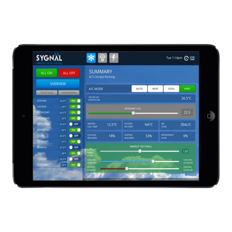
SAI Connect User manual

1
Copyright. Sygnal 2018
Sygnal Ambient Intelligence
Connect Operations Manual

2
Copyright. Sygnal 2018
Publisher
Sygnal Ambient Intelligence
Phone 1300 844 429
Internet www.sygnal .com.au
Revision 07.11
This Technical Manual describes the service and troubleshooting of Sygnal Digital Inverter Ducted split air
conditioners.
Copyright
This publication is Copyright © 2018 Sygnal. All rights reserved. No part of this publication may be reproduced,
stored in any retrieval system or transmitted, in any form or by any means, electronic, mechanical,
photocopying, recording or otherwise, without the prior written permission of Sygnal.
Disclaimer
Sygnal reserves the right to make changes and improvements to any of the products described in this
document without prior notice. Under no circumstances shall Sygnal be responsible for any loss of income or
any special, incidental, consequential or indirect damages howsoever caused.
Warranty
The contents of this document are provided “as is”. Except as required by applicable law, no warranties of any
kind, either express or implied, including, but not limited to, the implied warranties of merchantability and
fitness or a particular purpose, are made in relation to the accuracy, reliability or contents of this document,
Sygnal reserves the right to revise this document or withdraw it at any time without prior notice.
Sourcing
Proudly designed and manufactured in Australia by Sygnal, an independent Australian-owned company.

3
Copyright. Sygnal 2018
Contents
1. Sygnal Connect Operation ..................................................................................................................4
2. Connect LCD Touchpad Functions ......................................................................................................5
2.1 Touchpad Layout...........................................................................................................................5
2.2 Turning all zones ON or OFF *.......................................................................................................6
2.3 Selecting the Conditioning Mode *...............................................................................................6
2.4 Selecting the Zone Mode * ...........................................................................................................6
2.5 Viewing a zones status *...............................................................................................................6
2.6 Turning a zone ON or OFF.............................................................................................................7
2.7 Setting a zone temperature / Position (setpoint).........................................................................7
2.8 Setting a return air temperature ..................................................................................................7
2.9 Naming a Zone ..............................................................................................................................7
2.10 Setting the System Clock *..........................................................................................................8
2.11 Setting the System Timer Program * ..........................................................................................8
2.12 Setting Individual Zone Timer Programs.....................................................................................9
2.13 Holiday, Away, Disable Time Clock Programs.............................................................................9
3. Room Controller operation...............................................................................................................10
4. Manufacturers Recommendations ...................................................................................................11
4.1 Essential Operating Guidelines ...................................................................................................11
4.2 Tips for saving energy .................................................................................................................11
4.3 Power Failures.............................................................................................................................11
5. Maintenance .....................................................................................................................................11
5.1 Return Air filter cleaning.............................................................................................................11
5.2 Outdoor Unit...............................................................................................................................11
5.3 Vents & Return Air Grill...............................................................................................................11
5.4 Controller ....................................................................................................................................11
6. Troubleshooting................................................................................................................................12
6.1 Digital Inverter System Diagnostics / Fault detection.................................................................13
6.2 Dual Inverter System Diagnostics / Fault detection. ..................................................................14
7. Warranty terms and conditions........................................................................................................15
8. Warranty key points in large print. ...................................................................................................16

4
Copyright. Sygnal 2018
1. Sygnal Connect Operation
Your Sygnal Connect control system coordinates the operation of the Sygnal indoor and outdoor units and
zone dampers to provide the finest indoor climate control solution currently available.
The system features variable refrigeration and airflow (VRAF) and multi-zone variable air volume (VAV)
capacity modulation to ensure the appropriate amount of heating or cooling capacity is distributed to each
area.
Individual temperature sensors located in the touchpad for each VAV zone detect subtle temperature
variations and the system responds by increasing or decreasing the amount of air to each area to maintain the
required comfort level.
While this is occurring the VRAF capacity matching system monitors the requirements of the space as a whole
and increases or decreases the conditioning output from the compressor and the speed of the indoor fan to
suite.
Timer programs allow you to schedule the start and stop time for the entire system and individual zone on and
off times to suit your needs.
To turn on your system simply press at any touchpad. In the default auto mode the system will begin
heating or cooling as required. When all areas are off the conditioning system shuts down.
Please read on for more information about controlling your indoor environment.

5
Copyright. Sygnal 2018
2. Connect LCD Touchpad Functions
The LCD touchpad allows you to adjust various aspects of your indoor climate. By default access to all control
functions are available from all LCD touchpads. Press any button on the touchpad to wake it (the LCD backlight
will come on).
Access to some control functions may be limited via hardware settings during installation. In the following
pages, functions which may be limited in this manner will be indicated with a * in the heading.
If access to a function has been limited the LCD touchpad will respond with a beep only. (For more information
refer to Sygnal Connect Installation Manual).
Access to the following functions is available by default from any LCD touchpad.
Turn all zones on or off at once.
Select the system operating mode (Heat, Cool, Auto, Vent).
View any zone status.
Turning any zone on/off.
Setting any zone target (temp set or flow set).
Select the individual zone mode (temperature or velocity target).
Naming a zone.
Setting the system clock and timer programs.
Setting individual zone timer programs.
2.1 Touchpad Layout
Liquid Crystal Display showing Global Screen with
scrolling system summary.
Adjust setpoint, scroll through options and change
variables.
Access parameter adjustment. Save variables and
advance to next field.
Scroll through available zones.
Turn system ON and OFF at global screen. Turns zones
ON and OFF at Zone screens.
Adjust the current time or program.
Access mode selection screen. Functions as back button
while in edit screens.
Adjust setpoint, scroll through options and change
variables.

6
Copyright. Sygnal 2018
2.2 Turning all zones ON or OFF *
1. Press ZONE or or until the global screen is displayed.
2. Press to turn all zones on or off as required.
General system information scrolls across the bottom line of the LCD when the system is on.
E.g. Fan=80% Cooling =60% Mode=Auto
2.3 Selecting the Conditioning Mode *
The mode of operation for the main air conditioning plant can be selected from global screen of the LCD
touchpads. The global screen can be identified by general system information scrolling across the bottom line
of the LCD.
E.g. Fan=80% Cooling =60% Mode=Auto
Auto –selects heat or cool as required
Heat –Heating only
Cool –Cooling only
Vent –Fan only –no heating or cooling
1. Press MODE to access the mode selection screen.
2. Use or to alter the mode.
3. Press SET and save and exit.
2.4 Selecting the Zone Mode *
The mode of operation for individual zones can be selected from each zone screen of the LCD touchpads. The
zone screen can be identified by the actual zone name being displayed.
E.g.
Temp Set –selects damper modulates to maintain target temperature
MotorSet –provides manual damper positioning in 5% steps regardless of room temperature.
1. Press MODE to access the mode selection screen.
2. Use or to alter the mode.
3. Press SET to save and exit.
2.5 Viewing a zones status *
1. Press ZONE or or to cycle from the global screen through each of the individual zone status
screens.
2. The current status of the selected zone is displayed on the second line of the LCD readout. If the
zone is on the zone status scrolls across the bottom of the display.
E.g. Setpoint=22.5°C, Temp=23°C
Living
3) Off
Living
3) Off

7
Copyright. Sygnal 2018
2.6 Turning a zone ON or OFF
1. Press ZONE or or to select a zone.
2. Press to turn the zone on or off as required.
2.7 Setting a zone temperature / Position (setpoint)
Zone damper behaviour is determined by whether a zone sensor is connected to the zone sensor output at the
zone control modules. If a sensor is detected the zone is configured for temperature control. If no sensor is
detected and the enable zone dipswitch is turned on the zone is configured for damper positioning control.
1. Press ZONE or or to select the target zone.
2. Press SET to adjust the target temperature / position.
3. Use or to adjust the set point to the desired level.
4. Press SET to save and exit
2.8 Setting a return air temperature
(Only use when all zones are in Flowset Mode)
When all zone mode settings = FlowSet a return air setpoint is used
1. Press or to select the global screen.
2. Press SET to adjust the return air target temperature.
3. Use or to adjust the setpoint to the desired level.
4. Press SET to save and exit.
2.9 Naming a Zone
Zone names must be eight characters in length. A blank character must be used to fill spaces where no letters
are required.
1. Press ZONE or or to select the zone to be named.
2. Press and hold SET for approximately 10 seconds to access the zone name edit function.
3. Use and to view all of the preset zone names (e.g. Lounge, Games etc. or Custom).
4. Press SET on your choice. See tip below.
5. Use or to change the first character of the zone name if required.
Set=22.5°C
Tmp=23.0°C
Set=85%
Pos=25%
Z1 Name:
(Custom)
Z1 Name:
Games

8
Copyright. Sygnal 2018
6. Press and hold or to scroll quickly through the available characters.
7. Press SET to move to the next character. Press MODE to return to the previous character to
correct mistake.
8. Repeat for all eight character spaces.
9. Pressing SET to accept the final character will save the zone name and the controller will return to
the standard display.
TIP: To accept one of the pre-set zone names, press SET repeatedly to accept each character including any
blanks until the controller reverts to the standard display.
2.10 Setting the System Clock *
1. Press or to select the global screen.
2. Press CLOCK to display the current time and date.
3. Hold SET for 10 seconds.
4. Use or to highlight Change Time and press SET.
5. Use or to alter the highlighted hours value then press SET.
6. Repeat for the minutes and day values.
7. Pressing SET after the day value will return you to the time clock summary screen.
8. Press CLOCK to exit and return to the zone summary screen.
2.11 Setting the System Timer Program *
1. Press or to select the global screen.
2. Press CLOCK to display the clock.
3. Hold SET for 10 seconds.
3. Use or to highlight ALL Zones program? Then press SET.
4. Use or to highlight desired program A or B then press SET.
5. The top line will scroll Program ALL Zones.
6. On the bottom line the days of the week are displayed. A CAPITAL letter indicates that the system
on/off times will apply on that day. Press to activate or to deactivate each day, then press SET
to move to the next day.
7. Press SET after the final day value to enter the start time. If no days have been activated the
configuration routine will exit at this point. If there are valid days the top line will scroll: Program
start: ALL Zones.
10:12pm Tu
Off
ram Days
sMTWTFs
Start: A
08:40 am

9
Copyright. Sygnal 2018
8. Use or to alter the start time to the correct value (in 10 minute intervals).
9. Press SET to proceed to the stop time. The top line will scroll: Program stop: ALL zones
10. Use or to alter the stop time then press SET to complete setting the global timer program
and return to normal operation.
2.12 Setting Individual Zone Timer Programs
1. Press ZONE or or to select the required zone.
2. Press CLOCK to display the current program days for that zone.
3. Press or to select Program A or Program B then press SET.
4. The top line will scroll Program Days:Zone x.
5. A CAPITAL letter indicates that the zone on/off times will apply to that zone on that day. Press
to activate, or to deactivate each day, then press SET to move to the next day. Repeat for each day.
6. Press SET after the final day value to enter the start time. If no days have been activated the
configuration routine will exit at this point. If there are valid days the top line will scroll Program
start: Zone x.
7. Use or to alter the start time to the correct value (in 10 minute intervals).
8. Press SET to save the start time and proceed to the stop time. The top line will scroll Program
stop: Zone x
9. Use or to alter the stop time. The top line will scroll Program stop: Zone x.
10. Repeat for each zone as required.
2.13 Holiday, Away, Disable Time Clock Programs
1. Select the Global screen.
2. Press CLOCK to display the current time.
3. Press to access TC Enable menu.
4. Use or to select Yes? Or No? and press SET.
5. TC Off will scroll with the system information when No? is selected.
Stop: AL
05:30 pm
Ram Days
sMTWTFs
10:12pm Tu
Off

10
Copyright. Sygnal 2018
3. Room Controller operation
Room controllers provide On/Off control for individual zones. When no temperature target is required for a
zone a room controller is not required.
Zone On/Off Button
Heating indicator LED
On/Off Indicator LED
Cooling Indicator LED

11
Copyright. Sygnal 2018
The air conditioning plant and control system contains no user serviceable parts. Installation, service and maintenance of these
components should be carried out by a suitably qualified technician.
4. Manufacturers Recommendations
The following information is a guide to efficient use of your new Sygnal system. Following these tips will
contribute to the long life of the unit and could save you money.
4.1 Essential Operating Guidelines
The Filters must be in place to run the unit. Never operate the unit without the filters.
4.2 Tips for saving energy
For optimum unit efficiency, cost benefit and comfort levels we recommend setting the temperature
between 20°C and 24°C for both heating and cooling.
By covering windows with blinds or curtains you increase the cooling (heating) efficiency.
Dirty air filters cause inefficient operation and reduce unit efficiency. Clean monthly by either vacuum
or hand wash in mild detergent.
Turn the system off at the circuit breaker (located near the outdoor unit) prior to going on holidays to
ensure timer programs don’t cause unnecessary operation.
4.3 Power Failures
Your new Sygnal system has a memory function that automatically stores settings in the event of a power
failure. After power is restored the unit will automatically re-start with the same settings active before the
power failure and in accordance with any timer setting. This feature covers all operating settings.
5. Maintenance
Regular maintenance will ensure your Sygnal system operates at maximum efficiency.
5.1 Return Air filter cleaning
Cleaning the filter in the return air grille is recommended every month. Filters may be cleaned by either
vacuum or hand wash in mild detergent. Never operate the air conditioner without the filter. Ensure the filter
is in good condition, if not contact your installer for a replacement filter (a charge will apply)
5.2 Outdoor Unit
Do not place any object in front of the condenser. Keep free of grass, leaves and any other form of debris. This
will allow for proper air flow and ensure unit efficiency.
5.3 Vents & Return Air Grill
Regular cleaning of the return air grill and air vents is recommended. This will prevent build-up of dust and
dirt.
5.4 Controller
Clean the wall control with a dry cloth. Do not use a spray detergent or water.
The control circuits for the indoor and outdoor units carry voltages > 240 VAC which can cause serious injury or death.

12
Copyright. Sygnal 2018
6. Troubleshooting
Problem
Possible Solution
Air Conditioner has restarted but does not operate
for 4 minutes
The normal operating behaviour to protect the
compressor. Wait until the air conditioner begins
operating.
Operation stops for up to 12 minutes during heating
and a different noise/sound comes from the unit.
The unit has entered defrost mode to melt the frost
which has accumulated on the outdoor unit. This
will take no longer than about 12 minutes so wait
for the unit to resume normal operation. (Frost
accumulates on the outdoor unit when the outdoor
temperature is low and the humidity is high. Water
comes out from the outdoor unit).
The air conditioner does not operate.
Has the mode been set correctly?
Is at least one zone ON.
Has the setpoint for ON zones been set low enough
for cooling or high enough for heating?
Has the circuit breaker been tripped?
The air conditioner does not cool/heat effectively.
Has the mode been set correctly?
Are all the windows and doors closed?
Are the filters dirty?
Are the intake or outlet vents of the outdoor unit
obstructed?
The outside temperature maybe below or above
design conditions. Turning OFF any zones not
required may help.
Abnormal noise is heard during operation (except
during the defrosting operation).
Water leaks from the indoor unit.
Switches or buttons do not operate properly.
Fault code is displayed on the controller.
Contact your installer. Your model and serial
number is recorded on the inside of the last page of
this booklet.

13
Copyright. Sygnal 2018
6.1 Digital Inverter System Diagnostics / Fault detection.
Sygnal systems are able to detect a number of problems and display a fault message to aid in troubleshooting.
If any fault messages are displayed contact your installer/service person.
Fault D1 –3 Phase error Digital Outdoor
Line1 = Fault D1:
Line 2 scrolls one of the following:
3 Phase, L2 & L3 lost
3 Phase, L2 lost
3 Phase, L3 lost
3 Phase, rotate L2 & L3
Fault D2 –Coil Sensor Error (sensor nominated)
Line 1 = Fault D2:
Line 2 scrolls the following:
Outdoor coil sensor open circuit
Outdoor coil sensor short circuit
Indoor coil sensor open circuit
Indoor coil sensor short circuit
Fault D3 –High pressure or Low pressure Fault
Line 2 scrolls one of the following:
HP compressor safety
LP compressor safety
HP/LP compressor safety
Fault D4 –Interconnect Indoor>Outdoor
Line 1 = Fault 4:
Line 2 scrolls one of the following:
AHU and Condenser Interconnect
Fault D5 –Contact Manufacturer
Line 1 = Fault 5:
Line 2 scrolls Contact Manufacturer
Fault D6 –Contact Manufacturer
Line 1 = Fault 6:
Line 2 scrolls Contact Manufacturer
Fault D7 –Zoning to Indoor Board Communications Lost
Line 1 = Fault D7:
Line 2 scrolls AHU and Zoning interconnect
Fault D8 –Contact Manufacturer
Line 1 = Contact Manufacturer

14
Copyright. Sygnal 2018
6.2 Dual Inverter System Diagnostics / Fault detection.
Sygnal systems are able to detect a number of problems and display a fault message to aid in troubleshooting.
If any fault messages are displayed contact your installer/service person.
Fault I1 –Indoor and Outdoor unit not compatible
Line1 = Fault I1:
Line 2 scrolls one of the following:
AHU and Condenser not compatible
Fault I2 –Coil Sensor Error (sensor nominated)
Line 1 = Fault I2:
Line 2 scrolls the following:
Outdoor coil sensor open circuit
Outdoor coil sensor short circuit
Indoor coil sensor open circuit
Indoor coil sensor short circuit
Fault I3 –Contact Manufacturer
Line 2 scrolls one of the following:
Contact Manufacturer
Fault I4 –Interconnect Indoor>Outdoor
Line 1 = Fault 4:
Line 2 scrolls one of the following:
AHU and Condenser Interconnect
Fault I5 –Contact Manufacturer
Line 1 = Fault 5:
Line 2 scrolls Contact Manufacturer
Fault I6 –Contact Manufacturer
Line 1 = Fault 6:
Line 2 scrolls Contact Manufacturer
Fault I7 –Zoning to Indoor Board Communications Lost
Line 1 = Fault I7:
Line 2 scrolls AHU and Zoning interconnect
Fault I8 –Contact Manufacturer
Line 1 = Contact Manufacturer

15
Copyright. Sygnal 2018
7. Warranty terms and conditions
All goods which are the company’s own are guaranteed against faulty workmanship, materials or design for a
period of 12 months from the date of despatch, after which all liability on the part of the Company ceases,
save:
a) Goods which are branded Sygnal, registered with Sygnal prior to the expiration of the standard 12 month
warranty period, form part of the air conditioning unit and are used in a human comfort application. These
goods are guaranteed against faulty workmanship, materials or design for a period of 60 months from the date
of system commissioning or 72 months from the date of despatch which ever expires first.
The Guarantee does not apply in the following cases:
b) Defect arising from materials supplied by the Purchaser or from a design requested by the Purchaser.
c) Replacements or repairs resulting from normal wear of units and machinery, corrosive atmosphere, damage
or injury caused by lack of care, insufficient inspection or maintenance, or improper use of the goods.
d) Failure attributable to fortuitous circumstances or “force majeure”
The guarantee consists of repairing, modifying or replacing the parts or units recognised as defective within
the shortest time at the Company's premises at the Company's expense save parts that are branded Sygnal
and form part of the air conditioner, these parts will be repaired at the installation location providing the
location is within 100km from the Company's premises or the premises of an appointed Agent or Dealer. The
guarantee is inclusive of parts and labour. Subject to the above, the Company’s liability and that of its resellers
is wholly limited to the original cost of the product sold. Any unauthorised repairs or alterations to the
equipment shall invalidate this warranty. In case of goods not of the manufacture of the company or its
principals, the Company undertakes that it will, if requested in writing by the Purchaser to obtain from the
manufacturer the benefit of any guarantee or warranty which the manufacturer may have expressly given as
top the quality or fitness for any purpose of the goods, except as may otherwise be provided for by law. The
fulfilment of this undertaking shall constitute the Company's sole liability in respect of any faulty goods of the
manufacture of the Company or its principals. Neither the reseller nor the Company shall be liable for any
injury, damages, expenses, or loss of pro t, direct or consequential, arising out of the use or installation of
products supplied by the Company all of which are supplied at the sole risk of the user. This warranty is in
addition to any statutory warranty which a Purchaser cannot waive but all other warranties are waived by the
Purchaser.
Sygnal Ambient Intelligence
Phone : 1300 844 429
Web: www.sygnal.com.au
Email: service@sygnal.com.au

16
Copyright. Sygnal 2018
8. Warranty key points in large print.
Sygnal HVAC systems used in human comfort applications are covered by a parts and labour on-site warranty
as explained in detail later in this document. Sygnal is committed to making sure that our clients get years of
trouble free operation from what we believe to be the world’s best residential concealed ducted air
conditioning system. Like all warranty policies the Sygnal HVAC warranty provides peace of mind for clients
and details the rights and responsibilities of Sygnal and the client.
HVAC systems like all machines require regular maintenance. If regular maintenance is not completed the
system operation is compromised and although Sygnal systems have many safety systems built into their
operation system longevity will be compromised. In most residential environments a single service per year
completed in accordance with the programmed maintenance schedule is sufficient to ensure that system
performance is not compromised and warranty terms and conditions are met.
Sygnal tracks all activity relating to your system and all other systems no matter where they are installed. This
allows us to make sure that all performance information is passed directly back to our Engineering Team so
that Future Sygnal systems can continue to set a new standard in product reliability. Tracking all system
activity also helps our Service Team identify any environmental factors, unusual activity or a repeat faults. To
achieve the required level of tracking to provide peace of mind for our clients we require that all systems are
registered on the Sygnal website within the first twelve months of operation. Immediately on completion of
the online registration form a unique identifier will be sent to the nominated email address, your system
warranty will be extended from twelve months to six years from date of manufacture or five years from date
of installation (whichever expires first).
1. Register your system: https://www.sygnal.com.au/register-your-system
2. Keep your system well maintained (If a fault occurs due to lack of maintenance or would have been rectified
sooner if noted during programmed maintenance your claim may be declined or reduced).
3. Be mindful of possible travel charges (is there an appointed service agent within 100km from your home?).
4. Be mindful of broader system components that are not unmanufactured by Sygnal and may have different
warranty terms and conditions (This may include iPads, motorised dampers, three phase soft start modules,
ductwork, diffusers and grilles).
5. Be mindful that in the rare event that a failure occurs the replacement component is covered by twelve
months or the remaining term of the system wide warranty whichever is the longest. System Registration
System Registration
Registration No. ………………………………………………………. Date Issued. ………………………………………………………………….
Table of contents
Other SAI Control System manuals
Popular Control System manuals by other brands

Vertiv
Vertiv Liebert Mini-Mate MT048 Installer/user guide

SkyLink
SkyLink AM-100 User instructions

Salus
Salus CO10RF quick start guide

Vahle
Vahle DCS1-PCB Translation of the original instructions

Intermatic
Intermatic PJB2175 Installation, operation & service manual

Optimus
Optimus SMM-8SA QuickGuide Installation