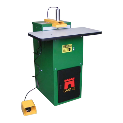
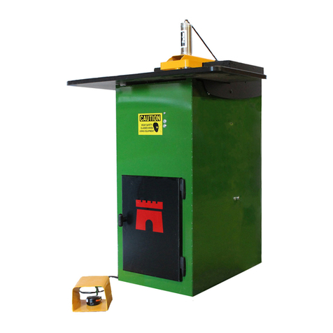
CASTLE TSM-21 User manual

CASTLE INC PO BOX 750236 PETALUMA CA 94975
WWW.CASTLEUSA.COM
Installation Instructions
TSM-21 Bosch Motor Carriage
CASTLE, INC.

CASTLE, INC TSM-21 Bosch Motor Carriage Install Page 2 of 25

CASTLE, INC TSM-21 Bosch Motor Carriage Install Page 3 of 25
Table of Contents
1INTRODUCTION.............................................................................................................................4
1.1 DEFINITION OF TERMS................................................................................................................4
1.2 IDENTIFICATION OF OPERATING FEATURES AND CONTROLS .........................................................5
2INSTALLATION INSTRUCTIONS ..................................................................................................6
2.1 SAFETY RULES..........................................................................................................................6
2.2 INVENTORY................................................................................................................................7
3REPLACING THE ROUTER CARRIAGE.......................................................................................8
3.1 REMOVING THE ROUTER STOP PLATE.........................................................................................9
3.2 REMOVING THE PORTER CABLE MOTOR CARRIAGE.....................................................................9
3.3 INSTALL THE NEW BOSCH MOTOR CARRIAGE ............................................................................10
3.4 INSTALL THE NEW ROUTER STOP PLATE ...................................................................................11
4FINAL INSTALLATION AND ADJUSTMENTS.............................................................................13
4.1 MOTOR REPLACEMENT ............................................................................................................13
4.2 CARRIAGE ADJUSTMENTS ........................................................................................................13
4.3 POCKET WEB ADJUSTMENT......................................................................................................14
4.4 POCKET DEPTH ADJUSTMENT ..................................................................................................15
4.5 DRILL FEED RATE ADJUSTMENT ...............................................................................................16
4.6 PILOT DRILL DEPTH ADJUSTMENT ............................................................................................17
4.7 PILOT DRILL HEIGHT ADJUSTMENT ...........................................................................................18
5SERVICE AND MAINTENANCE ..................................................................................................20
5.1 TOOL CHANGES.......................................................................................................................20
5.2 POCKET ROUTER BIT...............................................................................................................20
5.3 PILOT DRILL BIT.......................................................................................................................22
5.4 GENERAL MACHINE MAINTENANCE...........................................................................................22
5.5 MOTORS AND BITS...................................................................................................................23
5.6 SERIAL NUMBER LOG...............................................................................................................25

CASTLE, INC TSM-21 Bosch Motor Carriage Install Page 4 of 25
1 Introduction
Thank you for purchasing a TSM-21 Bosch Motor Carriage upgrade. Since 1985 our goal is to
manufacture and develop machines that make cabinetmaking and casework easier, faster, and
more profitable for woodworking professionals.This upgrade represents our patented screw
pocket cutting technology. Castle machines are made in Petaluma, California and are
manufactured to the highest standards using local vendors wherever possible.
The Castle model TSM-21 is designed for use on a wide variety of materials. The machine
performs well in hardwoods, softwoods, melamine, particleboard and MDF. The machine will
work on materials varying in thickness from ½” to 1 ¾”.
Warning: Do not attempt to perform maintenance or operate this machine until you have read and
understand the information contained in this manual.
1.1 Definition of Terms
TERM DEFINITION
Pocket The depression cuts into material to allow for toe-screw mortise joinery.
Pocket Cycle The procedure by which the machine clamps the work piece, cuts the
mortising pocket, drills the pilot hole, then releases the work piece.
Web The offset distance from the end of the pocket to the edge of the work piece.

CASTLE, INC TSM-21 Bosch Motor Carriage Install Page 5 of 25
1.2 Identification of Operating Features and Controls
Router Stop Plate: Located just inside the rear door, this black metal
plate extends through the top of the case and along the right side of
the Clamp Guard. The position of this plate determines the size of the
“Web.”
Safety Buttons: Two small, silver button-head screws under the
Clamp Guard detect if a work piece is in place for pocketing. The
machine will not cycle unless these buttons are depressed
simultaneously with the Foot Pedal.
Motor Carriage: The Motor Carriage is the yellow, pivoting A-frame
structure inside the machine. Both the Router Motor and the Drill
Motor are mounted to this carriage. The forward and back carriage
motion during the machine cycle is provided by the Drive Cylinder.
Drive Cylinder: This double-acting pneumatic cylinder connected to
the Motor Carriage and the machine case, moves the carriage
through the routing and drilling phases of the cycle. When the
cylinder rod extends (moving the carriage toward the rear) the router
cuts the pocket. When the cylinder rod retracts (moving the carriage
forward) the pilot drill bores the pilot hole into the pocket.
NOTE: SQE valves are replaced by elbow fittings in models with
Serial Number 62481 and higher.
Router Stop Switch: This magnetic proximity switch is mounted on
the Router Stop Plate inside of the machine. At the full extension of
the routing stroke, the carriage interrupts this switch to signal the start
of the drilling stroke.

CASTLE, INC TSM-21 Bosch Motor Carriage Install Page 6 of 25
2 Installation Instructions
These instructions are intended to illustrate how to remove the motor carriage designed for
Porter Cable motors and replace it with a carriage designed for Bosch motors. At the same time
the Router Stop Plate must be changed as the old style will interfere with the Bosch carriage
movement.
2.1 Safety Rules
The Castle Model TSM-21 Pocket Machine was designed with operator safety as a priority,
which is why Castle highly recommends the following:
1. Read this Instruction Manual carefully before beginning the carriage exchange.
2. Before attempting adjustments, maintenance, or repair, TURN OFF this machine,
disconnect it from its power source and air supply. Wait for all motion to stop.
Failure to disconnect this machine from its power source and air supply or wait for all
motion to stop could result in electrocution or injury.

CASTLE, INC TSM-21 Bosch Motor Carriage Install Page 7 of 25
2.2 Inventory
With your Castle TSM-21 Bosch Motor Carriage upgrade pack you should have received the
following:
CASTLE TSM-21 Bosch Carriage Upgrade Parts
Part # Part Description Qty
G21123 TSM-21 Router Carriage – Bosch 1
N21142 TSM-21 U-Bolt (Router) Installed 1
N21143 TSM-21 U-Bolt (Trimmer) Installed 1
H00141 ¼-20 Bar Knob Installed 2
G21007 TSM-21 Rear Stop 1
D21638 Bosch 3/8” Collet for Router Motor 1
F01420 1/4-20 Nylon Insert Locknut 3
Lithium Grease 1
With purchase of Upgrade Kit with motors:
E21610 Bosch PR20EVS 1.0 HP Motor 1
E21617 Bosch 1617 2 HP Motor 1
B00338 Solid Carbide, 3/8” Rough Mill Three Flute Router Bit 1
B02964 9/64” Brad and Spur Premium Drill Bit with ¼” Shank 1

CASTLE, INC TSM-21 Bosch Motor Carriage Install Page 8 of 25
3 Replacing the Router Carriage
Caution: Make sure your machine is unplugged from its electrical outlet and the air
supply has been detached.
These instructions will detail the steps required to upgrade your TSM-21 to use Bosch Motors.
Videos of these processes are available on line.
Here are the steps detailed in this instruction guide:
•Remove the Router Stop Plate (3.1)
•Remove the Porter Cable Router Carriage (3.2)
•Install the Bosch Router Carriage (3.3)
•Replace the Router Stop Plate (3.4)
•Adjust the carriage and center the pocket and pilot hole (4.1)
•You must adjust carriage to center after installation to reset drill and router
alignment. Please see section 4.2 once you have installed both motors
in the new carriage.

CASTLE, INC TSM-21 Bosch Motor Carriage Install Page 9 of 25
3.1 Removing the Router Stop Plate
Note: Marking the location of the Router Stop Plate on the yellow Clamp guard will
save time and keep the same web depth when installing the new Router Stop
Plate.
•From the back door use a Phillips Screw Driver remove the screws holding the switch portion
(wires attached) of the two piece Router Stop Switch. (Save for installation of new stop
plate.)
•The switches are held in place with square nuts (save for installation of new stop plate).
•From the top of the machine use a 7/16 wrench to remove the ¼-20 Nylock Nut
•Remove the washer (save for installation of new stop plate)
•Push the bolt through into the clamp guard and remove by reaching through the back door
and up into the clamp guard. (Save for installation of new stop plate.)
•Remove the old plate by angling the top of the Router Stop Plate through the slot next to the
clamp guard and removing through the back door.
•Remove the magnet portion of the Router Stop Switch
•Save magnet, screws, and square nuts for installation of new stop plate.
3.2 Removing the Porter Cable Motor Carriage
•Remove the Porter Cable motors from the Carriage.
•Disconnect the Spring from the Carriage with a pair of pliers but leave attached to the case.
•Disconnect the Drive Cylinder from the Carriage but leave attached to the case.
•Remove the cotter pin from the clevis pin (save for installation of new carriage)
•Remove the clevis pin from the rod clevis (save for installation of new carriage)
Note: Removing the Work Top will allow easier access to the router motor, spring,
and drive cylinder.
•Remove the Set Screws on the sides of the machine
•Loosen the ¼-20 Nylock nuts with a 7/16 Wrench

CASTLE, INC TSM-21 Bosch Motor Carriage Install Page 10 of 25
•Use a 1/8” Allen Wrench to loosen and completely remove the Set Screws (save for
installation of new carriage)
•Through the back door twist the Motor Carriage to remove from the Bearing Jacks.
•The carriage will release with the Brass Hex Pivot Bushings in place
•Remove the old Motor Carriage through the back door
•Remove the Brass Hex Pivot Bushings from the carriage
•Wipe out to remove old grease and any sawdust or debris buildup
3.3 Install the new Bosch Motor Carriage
Note: We suggest that you test install the drill motor in the new carriage before it is
in the case. The drill motor is held in place by two braces on either side of the u-
bolt, and rests against a stop at the front. You will need to remove it before in-
stalling the carriage.
•Re-grease the Brass Hex Pivot Bushings with lithium grease (provided)
•Place Brass Hex Pivot Bushings on new Motor Carriage
•Move the new carriage into the machine through the back door.

CASTLE, INC TSM-21 Bosch Motor Carriage Install Page 11 of 25
Note: The U-Bolt to hold the router in place should face to the front of the machine,
and the bar knob used to tighten the pilot hole motor should face to the left as
viewed from the back of the machine.
•Hold the carriage at an angle and align the Hex Brass Pivot Bushings within the slots of the
bearing jacks
•Twist / push carriage until the Brass Hex Pivot Bushings are fully seated at the front of the
bearing jacks
Note: There will be a slight bulge on each side of the machine at the pivot point.
This is normal and necessary for the correct operation of the machine.
•Replace the reserved Set Screws with 1/8” Allen Wrench
•Reattach Spring to Carriage
•Reattach Drive Cylinder to Carriage using reserved Clevis Pin and Cotter Pin
3.4 Install the new Router Stop Plate
•Using the retained screws and square nuts, attach the magnet to the new Router Stop Plate
in the same position it was before.
•From the back door slip the top of the Router Stop Plate through the slot in the top of the
machine next to the clamp guard.
Note: When installing the Router Stop Plate make sure the plate that holds the
Router Stop Switch is to the left of the trimmer motor and the switch and magnet
are mounted facing the front of the machine.
•Replace the reserved carriage bolt through the clamp guard to hold the Router Stop Plate in
place. Use the mark made on the clamp guard to position the Router Stop Plate.
•Replace reserved washer and tighten with new ¼-20 Nylock nut and 7/16 wrench.
•From the back door replace the switch portion of the Router Stop Switch with the reserved
screws and square nuts.

CASTLE, INC TSM-21 Bosch Motor Carriage Install Page 12 of 25
Note: The Router Stop Switch magnet and switch should be as close together as
the spacing on the plate will allow without interfering with the travel of the carriage.
Leave the screws slightly loose to help with positioning later.

CASTLE, INC TSM-21 Bosch Motor Carriage Install Page 13 of 25
4 Final Installation and Adjustments
4.1 Motor Replacement
•Install the Bosch Model 1617 Router Motor in the carriage by slipping it through the carriage
and up into the U-bolt. Make sure it is seated at the top.
•Tighten with the bar knob.
•Plug in motor.
Note: Removing the Work Top will allow easier access to the router motor for cor-
rect placement.
•Install the Bosch PR20EVS Trimmer Motor in the carriage. Make sure it is seated correctly.
•Tighten with bar knob.
•Plug in motor.
4.2 Carriage Adjustments
•Adjust the carriage right or left with the set screws to position the carriage so that the router
bit is centered in the machine, using the hole for the drill as a reference point. The pilot hole
will be adjusted separately.
•Once the carriage is centered based on the location of the router bit, tighten the lock nuts on
the sets screws while holding the set screws in position with an Allen wrench.
•The drill is centered by adjusting the nut located below and to the front of the Drill Motor T-
Handle.
•Adjust the nut as needed to position the pilot hole bit in the center of the hole in the case,
and to the center of the pocket.
Note: Only tighten the nut as needed. Overtightening can reduce the ability to
move the bit in the opposite direction.

CASTLE, INC TSM-21 Bosch Motor Carriage Install Page 14 of 25
4.3 Pocket Web Adjustment
The offset distance from the end of the pocket to the edge of the work piece is called the “Web.”
(Fig 9) It has been factory set at approximately 7/8” to accommodate 1 ½” screws.
Fig 9
If you are using 1¼” screws you may choose to shorten the Web to 5/8”.
Note: The minimum recommended Web under any circumstance is 5/8”.
The Web is adjusted by shortening or lengthening the travel of the router’s cutting stroke.
•Locate the Router Stop Plate nut on the right side of the yellow Clamp Guard on top of the
machine. (Fig 10)
Fig 10
•Loosen the nylon locking nut.
•To shorten the Web, slide the black Stop Plate toward the rear of the machine slightly.
•To lengthen the Web, slide the plate toward the front of the machine slightly.
Web

CASTLE, INC TSM-21 Bosch Motor Carriage Install Page 15 of 25
Note: When the desired position has achieved, tighten the nylon locking nut secure-
ly to prevent shifting during operation. Subsequent adjustment of the Router Stop
Switch may also be necessary (Page 31).
4.4 Pocket Depth Adjustment
The router bit for cutting the pocket is inserted into the router collet at the factory for a distance
of 1 1/8” from the tip of the bit to the collet. This setting cuts at an optimal depth of approximately
3/8” for material between 5/8” and 7/8” thickness.
To cut a shallower pocket (in ½” material for example):
•Place a shim with a known thickness on the work top and place your work piece over it.
To cut a shallower pocket:
•Remove the router motor as described in the section for “Tool Changes”.
•Loosen the motor collet and slide the bit to the desired exposure. (If the bit does not move
easily, try gently tapping on the bit near the collet with a wrench.)
•Secure the collet and reinstall the router motor.
For your convenience, a blank Bit Gauge (Fig 11) is included with your
machine so that you may scribe a mark to record the depth that is most
suitable for your purposes. Refer to the “Pilot Drill Depth Adjustment” for
this procedure.
Fig 11

CASTLE, INC TSM-21 Bosch Motor Carriage Install Page 16 of 25
4.5 Drill Feed Rate Adjustment
The stroke speed with which the machine drills the pilot hole (and clamps the work piece) is
solely a function of the air pressure set at the internal Pressure Regulator. There is no separate
adjustment knob.
Note: If the Drill Feed Rate is so fast that the machine shakes violently during the
Pocket Cycle or if the Drill Feed Rate is so slow that the Pocket Cycle is significant-
ly longer than two seconds, then it may be necessary to adjust the Pressure Regu-
lator.Do not adjust the internal Pressure Regulator unless absolutely necessary.
The internal Pressure Regulator knob is located on the Control Box (Fig 12), just below the
duplex power outlet for the Router and Drill motors. If in doubt whether the internal Pressure
Regulator is set correctly, follow the steps described below:
Fig 12
•Unlock the knob by pulling it slightly away from the Control Box.
•Turn the knob counter-clockwise until it reaches a mechanical stop.
•Turn the knob clockwise five full revolutions (it’s helpful to make an index mark on the knob.)
•Lock the knob by pushing it slightly toward the Control Box.

CASTLE, INC TSM-21 Bosch Motor Carriage Install Page 17 of 25
4.6 Pilot Drill Depth Adjustment
The Pilot Drill operation works best when the drill depth is adjusted so that the drill bit just barely
breaks into the pocket. If the drill bit extends farther than necessary, it can cause shorter bit life
and over-size holes. The drill bit is set at the factory for a length of approximately 1 13/16” from tip
to drill motor collet (this is a suitable distance for the factory default 7/8” Web). As a general rule,
if the Web is decreased, then the Pilot Drill depth should also be decreased.
To adjust the Pilot Bit Depth:
•For your convenience, a blank Bit Gauge (Fig 13) is included with your machine so that
you may scribe a mark to record the depth that is most suitable for your purposes.
Fig 13 Fig 14
•Simply set the Bit Gauge on top of the collet and use any sharp object to scratch a
reference line in the soft aluminum where each bit should be. (Fig 14)
•The plate has two sides that can be used as settings for different processes in the shop.
•Remove the Pilot Drill Motor as described in the section for “Tool Changes”.
•Loosen the motor collet and slide the bit to the desired height. (If the bit does not move
easily, try gently tapping on the shank of the bit near the collet with a wrench.)
•Secure the collet and reinstall the router motor.

CASTLE, INC TSM-21 Bosch Motor Carriage Install Page 18 of 25
4.7 Pilot Drill Height Adjustment
The position of the Pilot Hole can be raised or lowered slightly to accommodate various
thickness in work pieces or various pocket depths.
•On the sides of the machine case, secure the Carriage Centering Screw with a 1/8” allen
wrench. Loosen - but do not remove - the nylon lock nuts securing the set screw of the Motor
Carriage to the machine case. (Fig 15)
Fig 15 Fig 16
Note: The left-to-right alignment of the Motor Carriage may shift if care is not taken
during the loosening of the nylon lock nuts. Make sure that each preload set screw
is secured with an allen wrench before loosening each lock nut.
•From the Rear Door of the machine locate the Bearing Jack plate on the inner wall of the
cabinet. (Fig 16)
•Loosen, but do not remove, the nut on the plate that is nearest to the carriage axle.
•Remove the nut and bolt on the plate that is farthest from the carriage axle.Typically this
nut and bolt are factory set to the center hole of the five holes on this end of the plate.
•To raise the pilot hole, slide the plate upward one or two hole positions (each hole position
equals 1/16” of drill position).To lower the pilot hole, slide the plate downward.

CASTLE, INC TSM-21 Bosch Motor Carriage Install Page 19 of 25
•Reattach the nut and bolt in the new hole position, and secure in place.
•Tighten the nut on the plate that is nearest to the carriage axle.
•Repeat for the other side.
•On the outside of the machine, secure the Carriage Centering Screw with a 1/8” allen wrench
and tighten the nuts securing the pivot point of the Motor Carriage to the machine case.

CASTLE, INC TSM-21 Bosch Motor Carriage Install Page 20 of 25
5 Service and Maintenance
5.1 Tool Changes
Caution: Do not attempt to change tooling with compressed air power supplied to the
machine!
You do not need to remove the Work Top to change the bits, but removal of the Work Top will
give access to the Router Motor. To change the Pocket Router Bit or the Pilot Drill Bit without
removal of the Work Top, you will need to remove the respective motors from the carriage.
5.2 Pocket Router Bit
•Open the rear door and unplug the router motor.
•Locate the black T-Knob to the right of the drill motor at the top of the carriage. The black T-
Knob is threaded onto a large U-bolt that secures the Router Motor.
•Support the bottom of the Router Motor with your left hand (Fig 21). Use your right hand to
loosen the T-Knob a few turns to provide slack on the U-bolt. (Push slightly forward on the
T-knob if necessary.)
Fig 21
Other manuals for TSM-21
2
Table of contents
Other CASTLE Cutter manuals
Popular Cutter manuals by other brands

Mafell
Mafell KSS 80 Ec/370 Original operating instructions and spare parts list

Primera
Primera LX400e manual

Husqvarna
Husqvarna 268K, 272K Operator's manual

Parkside
Parkside PPKS 35 A1 Operation and safety notes

Makita
Makita DPC7311HD Instruction and safety manual

Darkly Labs
Darkly Labs Emblaser Core user manual