Kuppersbusch EKV 6200.0E User manual

Built-in automatic coffee machine
EKV 6200.0E
EKV 6500.0E

Responsible: Dieter Rutz KÜPPERSBUSCH HAUSGERÄTE AG
Email: dieter[email protected]
Tel.: +49 209 401-732 Customer Service
Fax: +49 209 401-743 Postfach 100 132
Date: 11.06.2013 45801 Gelsenkirchen
Service Manual: H6-52-01

Service Manual 3
Nur zum internen Gebrauch
Contents
1. Safety...............................................................................................................................4
2. Technical data (date: 16.10.2009)..................................................................................5
2.1 General..................................................................................................................5
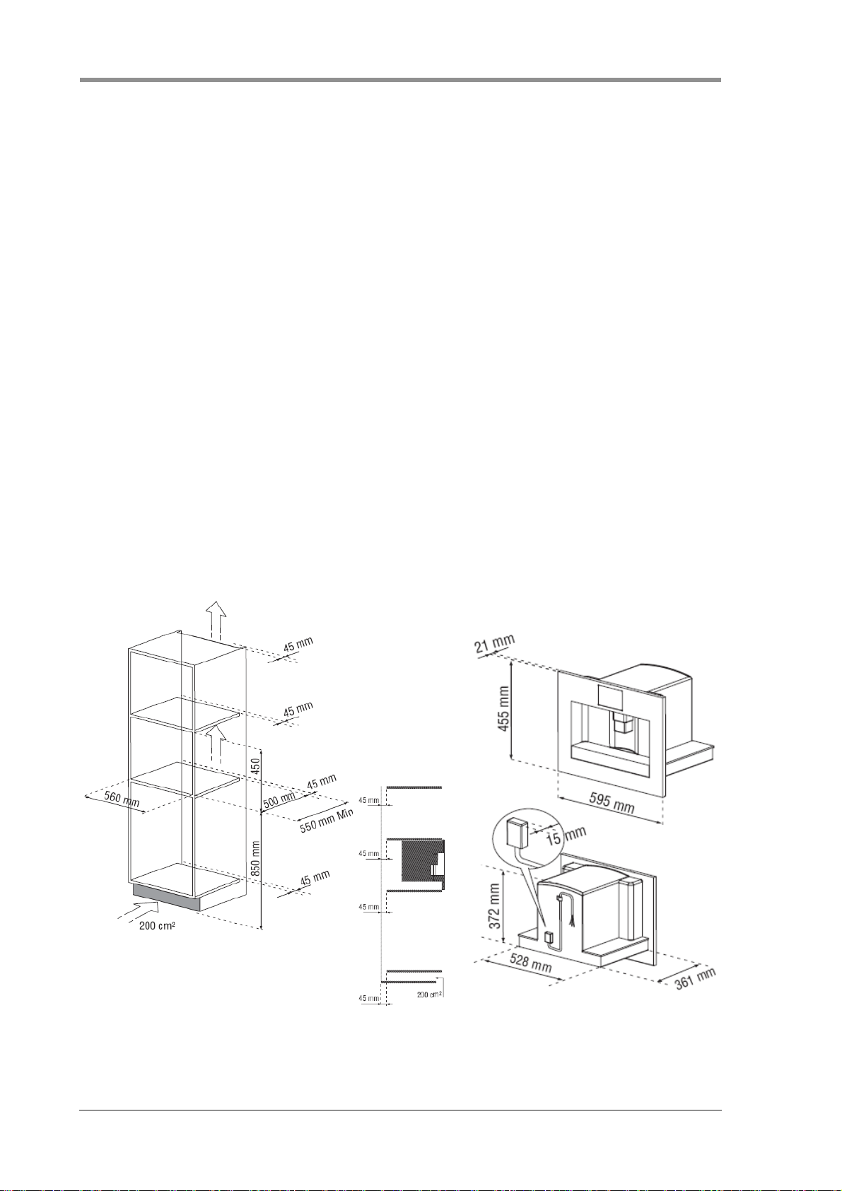
3. Installation.......................................................................................................................6
3.1 Installation instructions..........................................................................................6
3.2 EKV 6200.0E assembly dimensions ....................................................................6
3.3 Installation.............................................................................................................7
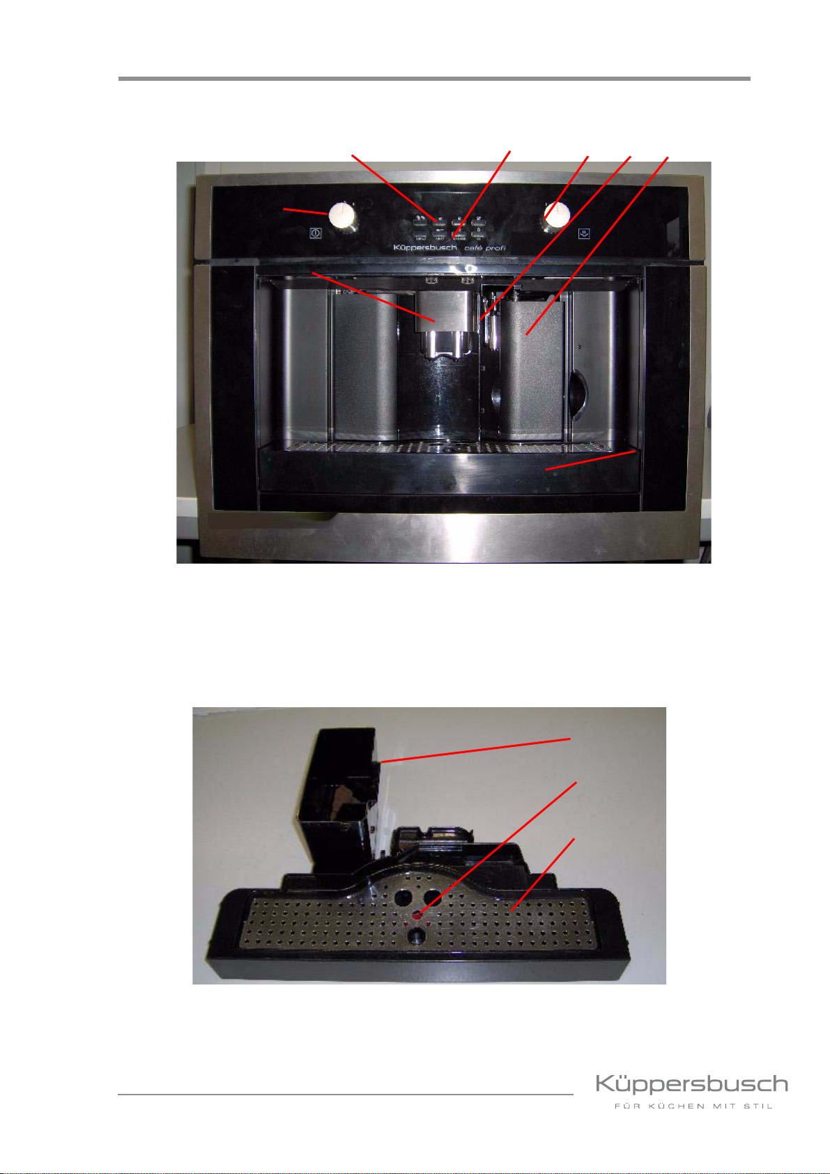
4. Your appliance at a glance ............................................................................................9
5. Button functions...........................................................................................................12
6. Test programmes ......................................................................................................... 13
6.1 EKV 6200.0E.......................................................................................................13
6.2 EKV 6500.0E.......................................................................................................16
7. Water flow diagram ......................................................................................................18
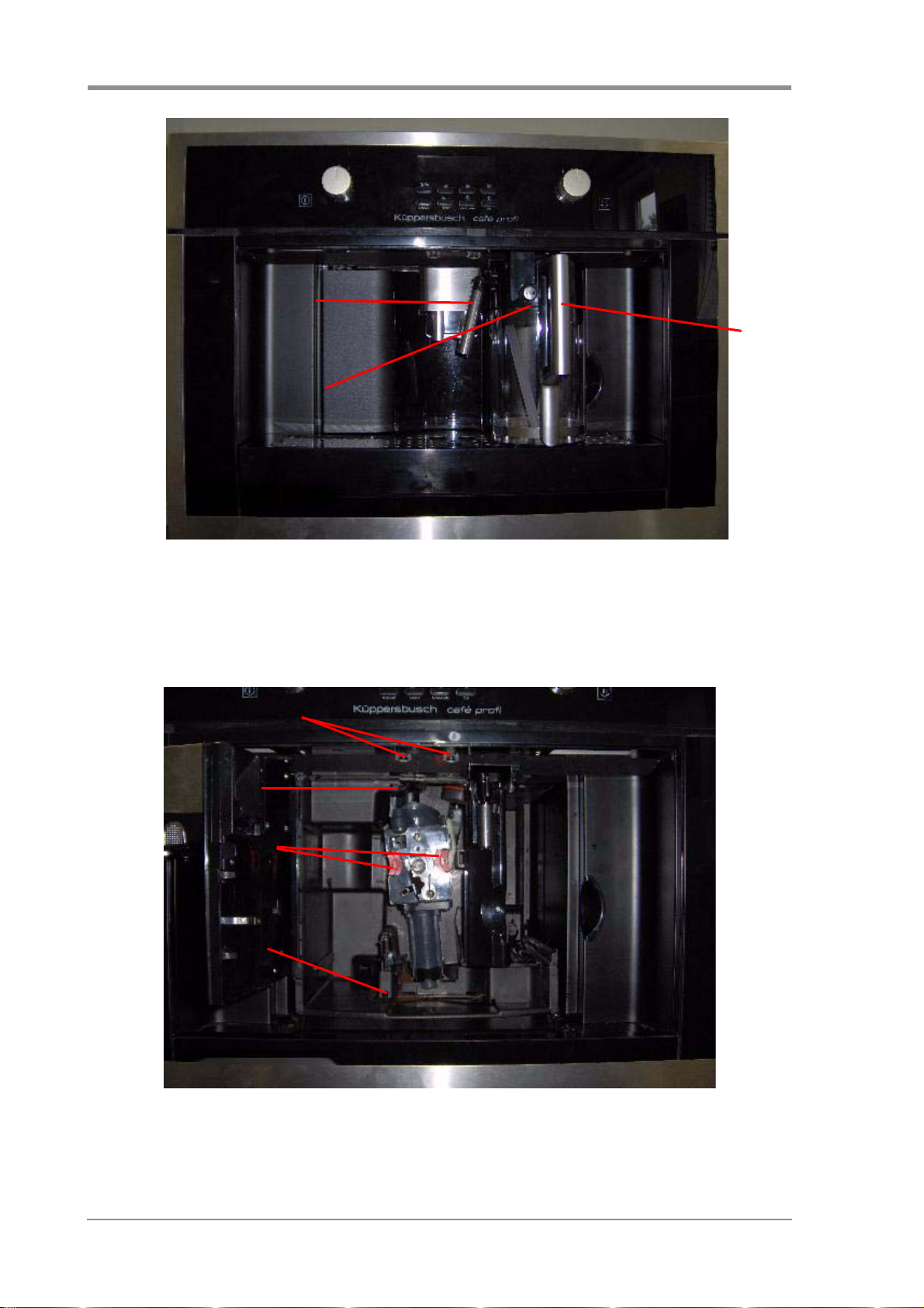
8. Accessing the individual components.......................................................................19
8.1 Removing and installing the brewing unit............................................................19
8.2 Removing the shelves.........................................................................................20
8.3 Removing the back appliance casing..................................................................20
8.4 Removing the front cover ....................................................................................21
8.5 Accessing the reed switch (water tank)...............................................................21
8.6 Accessing the flow metre ....................................................................................22
8.7 Removing the pump ............................................................................................22
8.8 Removing the top cover ......................................................................................23
8.9 Removing the continuous flow heater (water).....................................................23
8.10 Removing the continuous flow heater (coffee water) ..........................................24
8.11 Removing the brewing group motor ....................................................................25
8.12 Removing the electronic unit...............................................................................26
8.13 Accessing the micro switch in the door ...............................................................26
8.14 Accessing the micro switch in the drip tray .........................................................27
8.15 Accessing the top micro switch in the brewing unit motor unit ...........................27
8.16 Accessing the lower micro switch in the brewing unit motor unit .......................28
8.17 Accessing the sensor electronics in the brewing unit motor................................28
8.18 Accessing the coffee holder................................................................................29
8.19 Working on the front panel and the electric controls ...........................................29
9. The grinder - setting.....................................................................................................31
10. Cleaning and care......................................................................................................... 33
11. Finding faults................................................................................................................34
11.1 Customer complaints...........................................................................................34
11.2 Technical faults ...................................................................................................37
12. Circuit diagram .............................................................................................................42

4 Service Manual
Nur zum internen Gebrauch
1. Safety
Danger!
Repairs may only be carried out by a qualified electrician!
Improper repairs can be extremely dangerous for the user.
It is essential that you observe the following instructions in order to prevent electric shocks:
• The casing and the frame may be live in the event of faults! Prior to repairs, disconnect the appliance
from the mains!
• Touching live components inside the appliance may cause dangerous currents to flow through your
body!
• Disconnect the appliance from the mains prior to carrying out any repair work!
• When inspecting live parts, a residual current circuit breaker must always be used!
• Always ensure that an earthed conductor is properly connected. The ground wire resistance must not
exceed that specified in the standard! It is vital for ensuring the safety of persons and the functioning
of the appliance.
• On completion of repairs, an inspection must be carried out in accordance with VDE 0701
[Association of German Electrical Engineers] or the corresponding regulations for your country! On
completion of repairs, a function and impermeability inspection must be carried out.
• Do not touch any of the components in the appliance. The modules are also live!
• Observe instructions on electrostatic hazards!
Please observe the following instructions:
• When taking measurements according to VDE 0701 above the connector plug, the universal switch-
off device (relay, circuit breaker) of the boiler means that it must be checked for insulation faults by
measuring it direct, or the residual current of the appliance must be measured.
• Pay attention to sharp edges in the stainless steel assemblies when replacing components.
• Disconnect appliances that are to be repaired from the power supply. It is absolutely essential to use
a residual current circuit breaker when tests need to be conducted on live parts.
Attention!
Sharp edges: Use protective gloves.
Components may be electrostatic!
Observe handling regulations!

Service Manual 5
Nur zum internen Gebrauch
2. Technical data (date: 16.10.2009)
2.1 General
This service manual serves to give specific information on the functioning of the appliances indicated in
the title to customer service technicians who already have the required technical knowledge to be able
to repair coffee machines.
Dimensions
Height 45.5cm
Width 59.5cm
Depth 42.0cm
Net weight 23kg
Gross weight 27.6kg
Niche dimension
(WxHxD) 560 x 450 x 550mm
Connected load 1.35kW
Voltage 220 - 240V / 50-60Hz
Power consumption 1350W
Connection cable 1.50m
Ready to plug in Yes
Standard accessories
Cappuccino pot
Alarm signals Optical
Capacitor 16µF 230V/50Hz
Transformer 230-18V 150VA 50/60Hz
Protectedwitha
safety fuse at 150°C
Transformer TA50 230V
LED (lamps) 1W
Light switch 2-pole
Resistance D10x55 18W 230V
Micro switches
Door Threepole,
changeover contact
Coffee grounds box Threepole,
changeover contact
Drip tray installed: Closed
Drip tray removed: Open
Micro reed water level sensor
With water Closed
No water Open
Coffee component
Temperature probe 98°C
Thermal fuse 192°C
Heating element 230V, 50Hz, 84Ω
NTC temperature sensor 98kΩ,26°C
1.2kΩ, 90°C
Solenoid valve (coil) 230V, 50Hz
2400Ω±7%
Over temperature protection Double-pole
breaker
(safety fuse)
Heating element
(electrical resistance) 600W + 600W
Pump type W UCLA EP5/48
Steam component
Temperature probe 145°C
Thermal fuse 318°C
Heating element
(electrical resistance) 1000W
Pump component
Pump 230V, 59Hz
Grinder component
Grinder 230V, 50Hz, 73Ω
Brewing unit motor
Limit switch top/bottom Closed
Motor 260V~, 243Ω

6 Service Manual
Nur zum internen Gebrauch
3. Installation
3.1 Installation instructions
• Statutory regulations and the connection specifications issued by the local power supply company
must be strictly observed.
• Before connecting the appliance to the mains power supply make sure that the power supply
complies with its intended voltage.
• The appliance must be disconnected from the mains for connection and repairs. Disconnect the
fuse.
• Ensure full protection against accidental contact when installing the appliance.
• Only connect the appliance to a wall socket that has been properly installed. The mains cable may
only be replaced by a qualified electrician who observes the relevant regulations.
• Safety regulations require that a universal isolator with a contact opening of at least 3mm be used
for installation.
• The built-in cupboard must be fastened firmly to the floor or to the walls as it is heavy and
this could make it fall over easily.
• The automatic coffee machine must be installed a safe distance from other heat sources such as
home appliances in order to prevent an excessive rise in temperature.
3.2 EKV 6200.0E assembly dimensions

Service Manual 7
Nur zum internen Gebrauch
3.3 Installation
Please note:
From June 2013:
Changing of the usual fixing screws equipment into torx and added 8 spacers
1. Remove the coffee machine from the packaging
and check to ensure that it is not damaged; if it is,
do not install it but contact the dealer.
2. Position the rails on the side of the unit as shown in
the diagram.
3. Fasten the rails with the corresponding screws and
then pull them out completely.
If the coffee machine is to be installed above a
“warming drawer“ (max. 500W), please position the
screws according to the top of the drawer. In this
case there is no shelf.
4. Place the appliance on the rails, making sure that
the pins are correctly positioned in their holders.
new

8 Service Manual
Nur zum internen Gebrauch
5. Fasten the connection cable with the corresponding
clip.
The connection cable must be long enough to be
able to pull the appliance out easily to fill up the
coffee bean holder. The appliance must be properly
earthed.
The electrical connection is to be carried out by a
professional electrician on observation of the
instructions supplied by the manufacturer and in
accordance with valid local regulations.
The socket must be easily accessible.
6. When adjusting the alignment of the appliance,
position the spacers supplied under the support or
on the side of it.

Service Manual 9
Nur zum internen Gebrauch
4. Your appliance at a glance
1Coffee pourer 2ON/OFF switch
3Plain text display 4Input keys
5Selector switch for milk froth 6Hot water discharge pipe
7Fresh water tank 8Drip tray
1Coffee grounds box 2Drip tray display
3Drip tray grid
46
13
„
7
5
&
2
3
8
1
2
3

10 Service Manual
Nur zum internen Gebrauch
1Milk froth dispenser nozzle
2Cleaning button
3Milk container
1Lamps 2Door micro switch
3Brewing unit lock 4Coffee grounds box micro switch
1
2
3
1
2
4
3

Service Manual 11
Nur zum internen Gebrauch
Features
• Programming for 3 different cup sizes
• Pourer for 1 or 2 cups
• Real cappuccino function (removable milk container)
• Option of using coffee beans or ground coffee
• Height-adjustable coffee pourer
• Lamps
• Brewing pressure of approx. 15 bars
• Separate boilers for coffee and hot water
• Automatic cleaning and descaling program
• Automatic rinsing cycle when the appliance is switched on and off
• Hot water function
• Water tank removable from the front
• Water filter
• Electronic push buttons
• Electronic clock with a date display
• Pre-set time
• Standby function (programmable)
•Reddisplays
•LEDlamps
• Central switch-off
• Temperature control for 3 different coffee temperatures
• Adjustable coffee flavour (5 pre-set coffee strengths)
• Appliance can be pulled out on rails

12 Service Manual
Nur zum internen Gebrauch
5. Button functions
The electronic touch buttons can be used to select various drinks at the push of a button. The buttons
are assigned in the factory. The individual buttons can be assigned to other drinks.
Factory pre-setting
1ON/OFF
2Coffee selector button
3Espresso selector button
4Plain text display
5Small coffee selector button
6Large coffee selector button
7Menu
8CONTINUE coffee pre-ground
9CHANGE rinse
AT OK hot water
A
K
Steam cappuccino
1 2 3 4 5 6
7 8 9 AT AK

Service Manual 13
Nur zum internen Gebrauch
6. Test programmes
6.1 EKV 6200.0E
6.1.1 Test programme: Components
Please proceed as follows to access this test programme:
1. Press and hold buttons 3and 6.
2. Insert the plug.
• Press button 7to switch on the coffee boiler heating element.
• Press button 8to switch on the fan and the lights.
• Press button 9to switch on the pump (only vibrate).
• Press button AT to switch on the grinder.
• Press button 1: motor up
• Press button 2: motor down
• Press button 3: EV 1 ON
• Press button 5: EV 2 ON
• Press button 6: Evaporator ON
• Turn the steam button AK: EV1 + EV2 ON
Please pull out the plug to end the test procedure.
1 2 3 4 5 6
7 8 9 AT AK

14 Service Manual
Nur zum internen Gebrauch
6.1.2 Test programme: Display
Please proceed as follows to access this test programme:
1. Press and hold buttons 5and 6.
2. Insert the plug.
3. The corresponding button number will be show each time the different buttons are pressed.
• When you turn the left button, the display will show 9 and 10.
• When you turn the right button, the display will show 11 and 12.
After one minute the display test will end automatically and the appliance will switch off.
1 2 3 4 5 6
7 8 9 AT AK

Service Manual 15
Nur zum internen Gebrauch
6.1.3 Test programme: Quantity metered
Please proceed as follows to access this test programme:
1. Press and hold buttons 7and 9.
2. Insert the plug.
The display will show
• the number of cups of coffee made
• the water consumption in litres
3. When button 8is pressed the display will show
• the number of descaling cycles carried out
After one minute the display test will end automatically and the appliance will switch off.
1 2 3 4 5 6
7 8 9 AT AK

16 Service Manual
Nur zum internen Gebrauch
6.2 EKV 6500.0E
6.2.1 Test programme: Components
Please proceed as follows to access this test programme.
1. Switch the appliance into the standby mode with button A21.
2. Open the service door and press and hold buttons C2, C7 and C10 simultaneously.
The display will show “Select Test”.
3. Close the service door and press button C4.
Press button C12 to switch on the pump (only vibrate).
Press button C10. The motor will start and the brewing unit will be raised. :
Press button C2 to switch on the coffee boiler heating element.
Press A21 to switch on the steam boiler.
Press button C6 to switch on EV 2.
Press button C3 to switch on EV 1 and the fan
Press button C13 to switch on EV1, EV2 and the light.
Press button C7 to switch on the coffee grinder.
Press button C4. The motor will go off and the brewing unit will be lowered.
Disconnect the appliance from the power supply or switch it off with the main switch to end the
procedure.

Service Manual 17
Nur zum internen Gebrauch
6.2.2 Test programme: Display
Please proceed as follows to access this test programme.
1. Switch the appliance into the standby mode with button A21.
2. Open the service door and press and hold buttons C2, C7 and C10 simultaneously.
The display will show "Select Test".
3. Press button C 2. The display shows 0.
Press button C 3. The display shows 1.
Press button C ???. The display shows 2.
Press button C13. The display shows 3.
Press button C ???. The display shows 4.
Press button C 4. The display shows 5.
Press button C 7. The display shows 6.
Press button C11. The display shows 7.
Press button C 9. The display shows 8.
Press button C10. The display shows 9.
Press button C 8. The display shows 10.
Press button C12. The display shows 11.
Press button C 6. The display shows 12.
Press button A 21. The display shows 13.
Disconnect the appliance from the power supply or switch it off with the main switch to end the
procedure.
The appliance may need to be set at the required language when the test programme has been
completed.

18 Service Manual
Nur zum internen Gebrauch
7. Water flow diagram
Coffee dispenser
Water tank
Water flow metre
Coffee heating element
Temperature
sensor
Steam heating element
Solenoid valve
for steam and hot water
Water pump
Temperature sensor
Outlet solenoid valve
Discharge pipe

Service Manual 19
Nur zum internen Gebrauch
8. Accessing the individual components
8.1 Removing and installing the brewing unit
=Attention!
The brewing unit may not be removed when the coffee machine is switched on.
=Do not attempt do remove the brewing unit with force since this may damage the coffee
machine.
1. Make sure that the coffee machine is switched off properly.
2. Open the service flap.
3. Remove the drip tray and the coffee grounds box.
4. Press the two red release buttons to the inside and at the same time remove the brewing unit
outwards.
=Attention!
Do not use any detergent to clean the brewing unit as the inside of the piston has been
smeared with grease. The detergent would remove the grease, causing the brewing unit to
stick and it would no longer be possible to use it.
5. Submerge the brewing unit in water for about 5 minutes and then rinse it under running water from
the tap.
6. Replace the brewing unit once it has been cleaned by placing it on the holder and on the pin that
has been positioned at the bottom. Press the PUSH lettering firmly until you hear it clicking into
place.
Unlock here

20 Service Manual
Nur zum internen Gebrauch
8.2 Removing the shelves
The shelves on the left and right can each be removed with three screws.
8.3 Removing the back appliance casing
Loosen the 8 screws and remove the back casing.
This manual suits for next models
1
Table of contents
Other Kuppersbusch Coffee Maker manuals

Kuppersbusch
Kuppersbusch EKV 6800.0 M User manual

Kuppersbusch
Kuppersbusch cafe profi EKVW6600 User manual

Kuppersbusch
Kuppersbusch EKV 6800.0 M User manual

Kuppersbusch
Kuppersbusch ekv6800.1m User manual

Kuppersbusch
Kuppersbusch CKK6350.0 Operation manual

Kuppersbusch
Kuppersbusch cafe profi EKV 6600.0 Installation guide

Kuppersbusch
Kuppersbusch EKV 6500 User manual

Kuppersbusch
Kuppersbusch cafe profi EKVW6600.1M-UL User manual

Kuppersbusch
Kuppersbusch EKV6200 User manual

Kuppersbusch
Kuppersbusch EKV 6600.1 E User manual