Kuppersbusch ESW 308.6 Operating instructions
GB
KÜPPERSBUSCH
CUSTOMER SERVICE
Repair Manual
ESW 308.6

Repair Manual
ESW 308.6
Internal use only 2
VKS-H
Contents
Contents . . . . . . . . . . . . . . . . . . . . . . . . . . . . . . . . . . . . . . . . . . . . .2
1. Introduction and Safety Instructions . . . . . . . . . . . . . . . . . . . . . . . . .3
2. Tools and Devices . . . . . . . . . . . . . . . . . . . . . . . . . . . . . . . . . . . . . .4
3. Functional Description of the Control Honeycomb . . . . . . . . . . . . . .5
4. Components of the Control Honeycomb . . . . . . . . . . . . . . . . . . . . .6
4.1 Power Sections . . . . . . . . . . . . . . . . . . . . . . . . . . . . . . . . . . . . . . . .6
4.2 Control System . . . . . . . . . . . . . . . . . . . . . . . . . . . . . . . . . . . . . . . .7
4.3 Disassembly of the Power Section . . . . . . . . . . . . . . . . . . . . . . . . .9
4.4 Disassembly of the Control System . . . . . . . . . . . . . . . . . . . . . . . .10
5. Adjustment and Balancing of the Sensors . . . . . . . . . . . . . . . . . . .11
5.1 Main Reset . . . . . . . . . . . . . . . . . . . . . . . . . . . . . . . . . . . . . . . . . .12
5.2 Automatic Calibration . . . . . . . . . . . . . . . . . . . . . . . . . . . . . . . . . .12
5.3 Calibration of Individual Sensors . . . . . . . . . . . . . . . . . . . . . . . . . .12
6. General Notes on Possible Faults . . . . . . . . . . . . . . . . . . . . . . . . .14
7. Instructions for replacing glass ceramic honeycomb units . . . . . . .15
Responsible: Rutz Tel.: (0209) 401-733 Fax: (0209) 401-743 Date: 17.10.1998
H1-58-01-02

3Internal use only
Repair Manual
ESW 308.6
VKS-H
1. Introduction and Safety Instructions
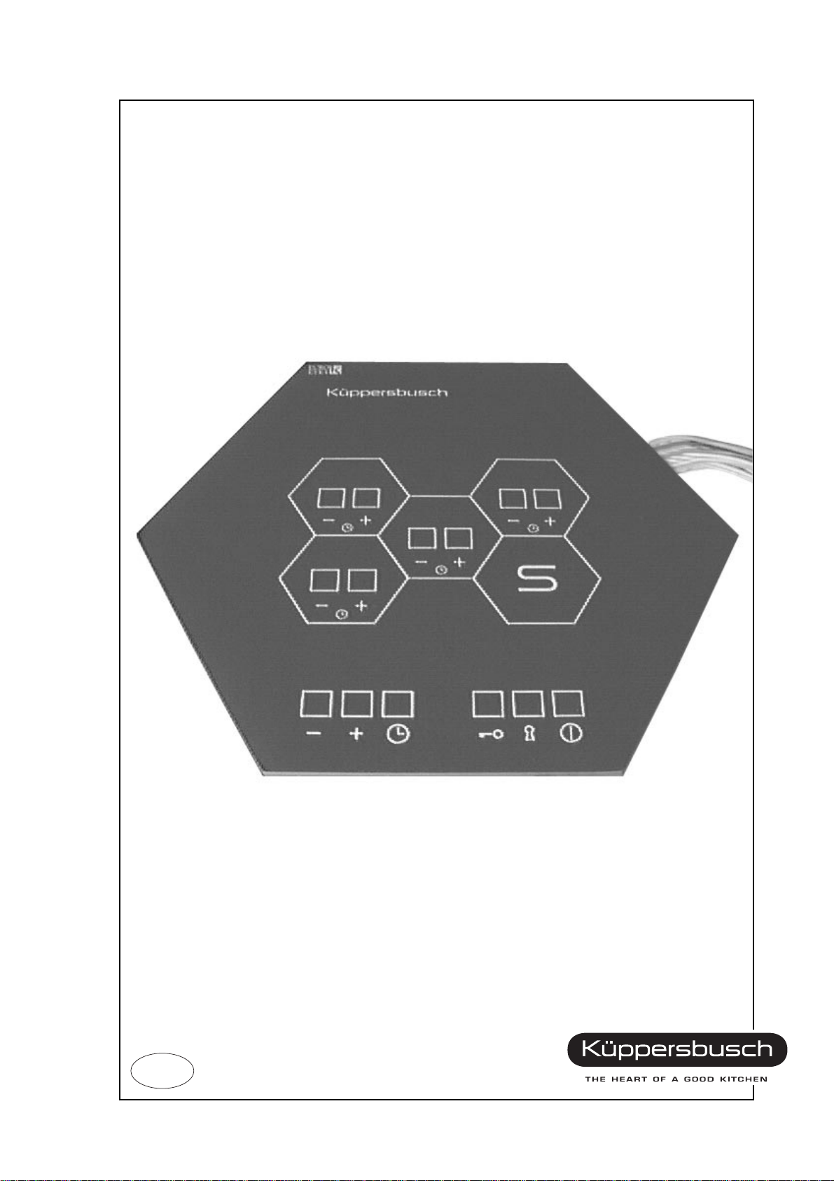
The control honeycomb ESW 308.6 is a sensor-controlled cooking honeycomb
which allows controlling of the cooking zones without contacting them.
In contrast to the forerunning model ESW 307.6, the ESW 308.6 is additionally
equipped with a minute minder. From the outside, however, the functions have
remained identical while the internal structure of the control electronics has
completely changed. With the ESW 308.6 manual balancing of the sensors is no
longer required. The control system will be automatically calibrated upon
commissioning (factory-set). If required, calibration may also be repeated at the
customer. However, it is also possible to manually adjust an individual sensor by
means of a special combination of the sensors. The calibration procedure is
dealt with in detail in a separate chapter.
Furthermore, power supply unit and power section of the ESW 308.6 have been
assembled on a joint printed-circuit board mounted on the lid. The connectors
have also been changed.
The appliances are manufactured in accordance with the applicable safety
regulations.
The appliances may only be connected up to the mains, serviced and repaired
by a qualified electrician according to the valid safety regulations. Work carried
out incorrectly will endanger your safety.
When the appliance is connected up to the mains it must be ensured that there
is a device which makes it possible to disconnect it from the mains at all poles
with a contact opening width of at least 3 mm. Line-protecting switches, fuses
and contactors are suitable cut-out devices.
Further general notes are included in the ”Operating and installation instructions
for honeycomb cooking areas with sensor control, series ESW/EKW”.
Before opening the appliance always disconnect it from the power supply!
H1-58-01-02

Repair Manual
ESW 308.6
Internal use only 4
VKS-H
2. Tools and Devices
The following tools are required for a trouble-free performance of a
customer service call:
••digital multimeter incl. measuring leads
••IC extraction tool for 28 poles
••small ratchet box
••5.5 mm socket spanner (type Belzer No. 6400-5.5)
••8.0 mm socket spanner
••side cutting pliers, small
••flat pliers, small
••screwdriver for slotted screws, various sizes (very important: with short handle)
••screwdriver for recessed head screws, various sizes (very important: with
short handle)
••torch, offset
Furthermore the following devices are required:
••setting device for basic calibration of the sensor system
••setting power supply unit
••glass cleansing agent, “Sidolin“ or similar
••cleaning cloths
H1-58-01-02

5Internal use only
Repair Manual
ESW 308.6
VKS-H
3. Functional Description of the Control Honeycomb
See Operating and Installation Instructions ESW, valid: July 1997
H1-58-01-02
Repair Manual
ESW 308.6
Internal use only 6
VKS-H
4. Components of the ESW 308.6
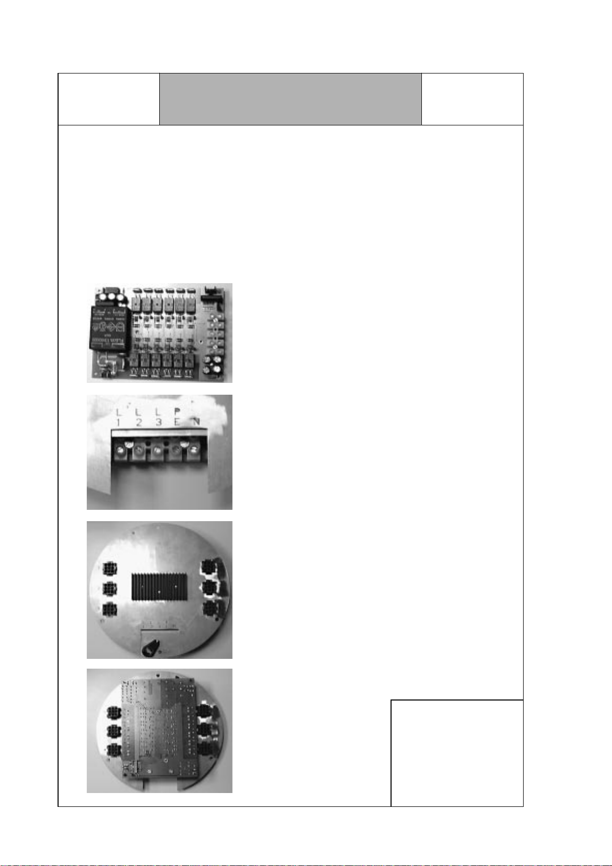
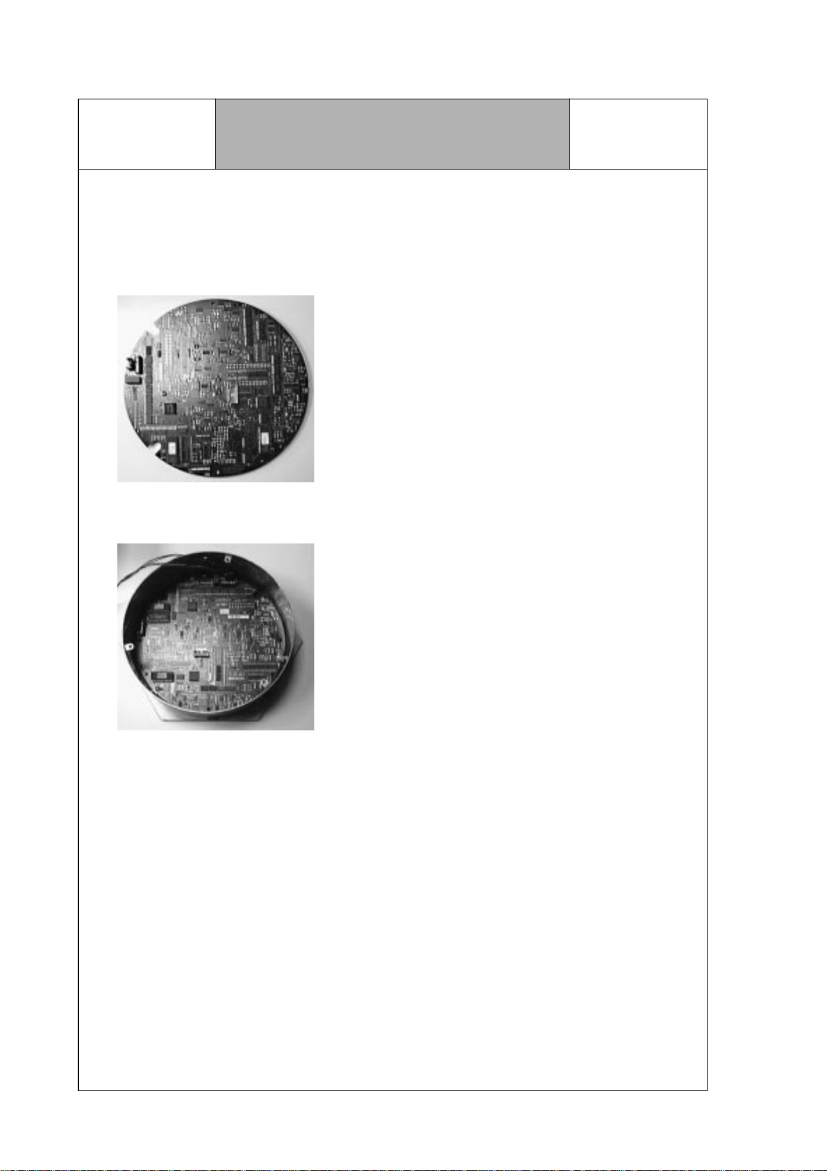
4.1 Power sections
Newly supplied control honeycombs starting with the W-number xxxx will be
equipped with the following combined power supply unit and power section:
power section 2879 - rev. A
electrical connection ESW 308.6
outside view of the lid ESW 308.6
power section mounted on lid
Note:
The power section may
be combined with any
of the forerunning
honeycomb models,
i. e., the control
connection is pin-com-
patible.
H1-58-01-02
7Internal use only
Repair Manual
ESW 308.6
VKS-H
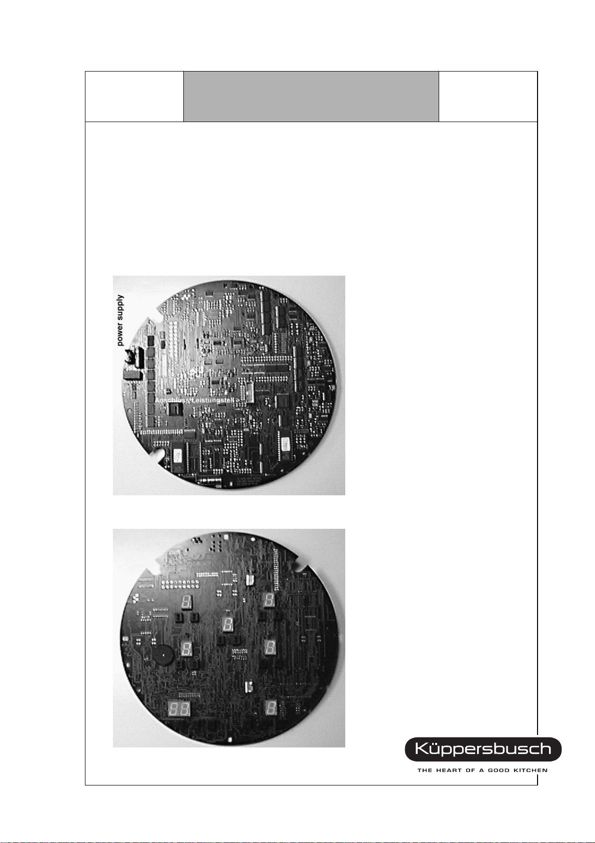
4.2 Control System
The control board is connected to the power section by means of 2 cables.
1. a 4-pole cable for power supply
2. a 14-pole ribbon cable for power section control
H1-58-01-02

Repair Manual
ESW 308.6
Internal use only 8
VKS-H
Before opening the appliance make sure
to observe the safety instructions!
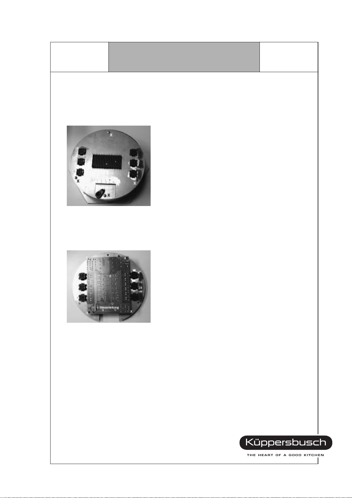
In order to loosen the lid of the cabinet unscrew the 4
screws (marked with an ”X”).
H1-58-01-02
9Internal use only
Repair Manual
ESW 308.6
VKS-H
After the appliance has been DIS-
CONNECTED FROM THE POWER SUPPLY
and the heater cables have been removed,
the 4
screws marked with an ”X” are removed (if
required, the incoming cable must also be
removed).
Then the connecting line to the control
system and the power supply are pulled off.
The pc board ”power section” is fastened by
means of 5 nuts marked with an ”X” in the
illustration below.
After removing the nuts the pc board can be
taken out of the fastening bolts.
Now the connecting cables can be pulled off
from the relays and the pc board be replaced.
Make sure that the terminal assignment at the
relays is the same before and after
replacement of the pc board.
Special terminal assignments will be made
available in the future. Assembly is then
performed in the reverse sequence.
Prior to commissioning the appliance has to
be checked again according to the valid
VDE-regulations!
Aprinted board assembly for all variations is
made available to the Customer Service.
(It may be included in the service box.)
4.3 Disassembly of the Power Section
H1-58-01-02
Repair Manual
ESW 308.6
Internal use only 10
VKS-H
control board
For the diassembly of the control board the
steps ”Removing and loosening the lid with
power section” have already been performed.
Afterwards the 3 fastening screws of the
control board are removed. The pc board is
removed towards the top with the recess
matching one of the top fastening brackets.
The new pc board is inserted and fastened
by means of the 3 screws.
The pc board is now illuminated from the rear
side by means of a torch so that the position
of the display elements can be checked from
above. In case the photo sensors of the
7-segment displays do not match the imprint
on the glass ceramic surface, the pc board
must be loosened again in order to position it
correctly. When the position then matches the
imprint, the 3 screws are tightened.
At this point the balancing procedure of the
sensors has to be performed. (See separate
description on the following pages!)
4.4 Disassembly of the Control System
H1-58-01-02
Other manuals for ESW 308.6
1
Table of contents
Other Kuppersbusch Control Unit manuals


Popular Control Unit manuals by other brands

Festo
Festo Compact Performance CP-FB6-E Brief description

Elo TouchSystems
Elo TouchSystems DMS-SA19P-EXTME Quick installation guide

JS Automation
JS Automation MPC3034A user manual

JAUDT
JAUDT SW GII 6406 Series Translation of the original operating instructions

Spektrum
Spektrum Air Module System manual

BOC Edwards
BOC Edwards Q Series instruction manual

KHADAS
KHADAS BT Magic quick start

Etherma
Etherma eNEXHO-IL Assembly and operating instructions

PMFoundations
PMFoundations Attenuverter Assembly guide

GEA
GEA VARIVENT Operating instruction

Walther Systemtechnik
Walther Systemtechnik VMS-05 Assembly instructions

Altronix
Altronix LINQ8PD Installation and programming manual


