Gasboy CFN Series Installation and operation manual

CFN SERIES
SITE CONTROLLER II
& ISLANDER II
START-UP MANUAL
C01665
GASBOY INTERNATIONAL LLC


GASBOY
CFN SERIES
SITE CONTROLLER II
& ISLANDER II
START-UP MANUAL
C01665
Rev. 03/07/03
GASBOY INTERNATIONAL LLC
LANSDALE, PA

Copyright 2003 by Gasboy International LLC
All rights reserved.
The information in this document is confidential and proprietary. No further disclosure shall be
made without permission from Gasboy International LLC.
Gasboy International LLC believes that the information in this document is accurate and reliable.
However, we assume no responsibility for its use, nor for any infringements of patents or other
rights of third parties resulting from its use. We reserve the right to make changes at any time
without notice.

03/07/03 Contents-1
CONTENTS
Section 1: STARTING A SITE CONTROLLER II SYSTEM
Introduction............................................................................................... 1-1
Start-Up Overview.................................................................................... 1-2
What You Need For Testing..................................................................... 1-3
Filling Out the Start-Up Form ................................................................... 1-3
Using This Book ....................................................................................... 1-4
Section 2:SITE INFORMATION............................................................................... 2-1
Section 3: BEGIN START-UP FORM
Parts 1 Through 6..................................................................................... 3-1
Section 4: PHYSICAL SYSTEM LAYOUT
Site Controller........................................................................................... 4-1
Islander..................................................................................................... 4-1
Island Card Reader Assembly.................................................................. 4-2
Pump Control Unit(s)................................................................................ 4-2
CheckPoint Console (Optional)................................................................ 4-3
Profit Point Console (Optional)................................................................. 4-4
Tank Monitoring System (Optional).......................................................... 4-5
Current Loop Interface (Optional)............................................................. 4-5
Fuel Point Components............................................................................ 4-5
Section 5: JUMPERS & SWITCH SETTINGS
Site Controller CPU PCB.......................................................................... 5-1
Jumpers .............................................................................................. 5-2
Switches.............................................................................................. 5-3
Pump Control Unit.................................................................................... 5-4
Pump Control EXPMUX CPU Board................................................... 5-5
Pump Control I/O PCB........................................................................ 5-8
Island Card Reader .................................................................................. 5-10
DIP Switches....................................................................................... 5-10
ICR CPU PCB Jumper Settings.......................................................... 5-11
Disable Pumps PC Board Jumper Settings ........................................ 5-11
Islander..................................................................................................... 5-11
Card Reader........................................................................................ 5-11
Communication Switch Settings.......................................................... 5-12
Jumpers and Connections .................................................................. 5-12
Disable Pumps PC Board Jumper Settings ........................................ 5-13
RS-232/RS-485 Converter ....................................................................... 5-14
POS Distribution Box (D-Box) .................................................................. 5-14
Fuel Point Reader..................................................................................... 5-15
Switch SW1......................................................................................... 5-15
Standalone Star Printer............................................................................ 5-16
Pumps and Dispensers ............................................................................ 5-16
Cabling and Port Jumper Configuration for Tokheim Pumps ............. 5-16
Cabling and Port Jumper Configuration for Wayne Pumps................ 5-17

CFN Series System
Contents-2 03/07/03
Section 6: SYSTEM POWER.................................................................................... 6-1
Section 7: PUMP/DISPENSER MANUAL TEST....................................................... 7-1
Section 8: COMPONENT POWER-UP AND CONFIGURATION............................. 8-1
Configuring the CheckPoint Console ....................................................... 8-3
Fluorescent Display Board.................................................................. 8-4
Configuring the Profit Point Console ........................................................ 8-5
Accessing the Main Menu................................................................... 8-5
Software Configuration........................................................................ 8-5
Hardware Configuration ...................................................................... 8-5
Keyboard Configuration....................................................................... 8-5
Scanner Configuration......................................................................... 8-6
Printer Configuration Submenu........................................................... 8-6
Link MC5 Terminal and Okidata Printer................................................... 8-7
Link MC5 Terminal Setup.................................................................... 8-7
Okidata 184 Setup............................................................................... 8-10
Site Controller Configuration Changes..................................................... 8-10
Series 9800 Electronic Pumps and Dispensers....................................... 8-11
Section 9: DC POWER MEASUREMENT AND ADJUSTMENT
Site Controller II........................................................................................ 9-2
Islander..................................................................................................... 9-3
Pump Control Unit(s)................................................................................ 9-4
Island Card Reader .................................................................................. 9-5
Islander (Satellite Reader)........................................................................ 9-6
CheckPoint............................................................................................... 9-7
Fuel Point Reader (FPR).......................................................................... 9-8
Profit Point................................................................................................ 9-9
Current Loop Interface ............................................................................. 9-9
Section 10: COMMUNICATION TESTS
General..................................................................................................... 10-1
Data Terminal........................................................................................... 10-3
Modem...................................................................................................... 10-3
Tank Monitor (Serial Port) ........................................................................ 10-4
Section 11: PUMP/DISPENSER AUTOMATIC TEST
Island Card Reader - Pump Activation Test (Optional)............................ 11-1
CheckPoint - Postpay Pump Activation Test (Optional)........................... 11-2
CheckPoint - Prepay Pump Activation Test (Optional When
Using Dual-Stage Solenoid Valves) ....................................................... 11-2
Profit Point - Postpay Pump Activation Test (Optional)............................ 11-3
Profit Point - Prepay Pump Activation Test (Optional When
Using Dual-Stage Solenoid Valves) ....................................................... 11-3
Before Using Fuel Point............................................................................ 11-4
Fuel Point Setup for Ground Loop Fueling............................................... 11-4
Fuel Point - Pump Activation Test............................................................ 11-4
Reader Entries and Fuel Point ................................................................. 11-5
Obtaining a Receipt for Fuel Point Transactions...................................... 11-5
Master/Satellite Dispensers with Fuel Point............................................. 11-5
Using the Chain Pump Feature with Fuel Point........................................ 11-6
Fuel Point – Gate Activation Test............................................................. 11-6

Introduction
03/07/03 Contents-3
Section 12: START-UP COMMANDS
Sign-on and Preliminary Steps................................................................. 12-1
Receipt Header, Broadcast Messages..................................................... 12-2
Load Fuel Products, Pumps, Tanks, Prices and Taxes........................... 12-2
Card Lockout............................................................................................ 12-5
Card Authorizations, Limitations............................................................... 12-5
Site ID and Remote Communications...................................................... 12-6
Load Merchandise/Departments, Prices, Inventory ................................. 12-7
Enable Devices......................................................................................... 12-7
Cash Drawer, Shifts.................................................................................. 12-8
Optional Features..................................................................................... 12-8
Reset Transaction File ............................................................................. 12-9
Diagnostics and History............................................................................ 12-9
Verification and Backup............................................................................ 12-10
Profit Point Setup...................................................................................... 12-11
Section 13: CUSTOMER TRAINING .......................................................................... 13-1
Section 14: FINISH START-UP................................................................................... 14-1
SAMPLE FILLED-OUT START-UP FORM
WARRANTY
FIGURES AND TABLES
Figures
5-1 Pump Control Unit Component Location.................................................................... 5-4
5-2 EXPMUX CPU Board ................................................................................................. 5-5
5-3 Pump Control I/O Cover Plate and PCB..................................................................... 5-8
5-4 Site Communications I/O PCB ................................................................................... 5-12
5-5 Fuel Point Reader (FPR) CPU PCB ........................................................................... 5-15

CFN Series System
Contents-4 03/07/03

03/07/03 1-1
Section 1
STARTING A SITE CONTROLLER II SYSTEM
INTRODUCTION
This Start-Up Manual is provided to assist you in the start-up of a GASBOY CFN Site Controller II
or Islander II System. The CFN Series System is a computerized data acquisition system. As the
start-up person, you should already be familiar with all the CFN Site Controller II and Islander II
manuals. Proper installation according to the CFN Site Controller II or Islander II Installation
Manual is critical to ensure correct and trouble-free operation. The CFN Site Controller II and
Islander II systems include a one year parts and labor warranty against defective material and/or
workmanship. See the Warranty page at the back of this book for details.
NOTE: Noncompliance with the specifications of the CFN Site Controller II or Islander II
Installation Manuals and the checks in the accompanying Start-up Form
could void the warranty.
As you are performing the start-up process, any deviations from the specifications listed in the
Site Controller II or Islander II Installation Manuals should be corrected. If any tests fail, correct
the wiring or system problem and perform the test again. If you have any questions, cannot
proceed to the next step, or you want authorization for exceptions, please contact GASBOY
Technical Service at: ☎1-800-444-5529
In addition to this manual, the customer should have these additional GASBOY CFN Series
manuals:
•Site Controller II Installation Manual, C01918
Contains instructions, restrictions and guidelines for planning, laying out, and wiring the Site
Controller II System.
•Site Controller II Site Manager's Manual, C09212
Contains detailed instructions for setting up or maintaining the Site Controller II. It also
contains descriptions of system features, data terminal commands, transaction processing
and system maintenance.
•Islander II Installation Manual, C35963
Contains instructions, restrictions and guidelines for planning, laying out, and wiring the
Islander II System.
Depending on the site configuration, the customer may also have these manuals:
•CFN Card Encoding Manual C01687
Describes the cards, field descriptions, layouts, and filling out the card encoding form.
Covers both encoding of mag cards and punching of optical cards.
•Debit and Credit Card Networks Manual
Formerly C09207, now based on router/network type. Describes the various network
interfaces for the Site Controller II.
•CheckPoint Reference Manual, C09204
Describes the operation of the CheckPoint Console.

CFN Series System
1-2 03/07/03
•Profit Point Reference Manual, C09203
Describes the operation of the Profit Point Console.
•Profit Point Clerk's Manual, C09201
Describes all point-of-sale operations for the Profit Point Console.
•Point of Sale and Shift Change Manual, C09215
Describes POS and shift change operations.
•Star Receipt Printer Manual C08951
Describes the operation of the Star Receipt Printer.
•Series 9800 Installation/Operation Manual 035235
Describes installation/operation for Series 9800 pumps/dispensers.
•Fuel Point Reader Installation and Retrofit Instructions Manual, C35628
•Fuel Point Dispenser and Hose Retrofit Manual, C35593
•Fuel Point Vehicle Module Installation Manual, C35699
•Fuel Point Vehicle Module Programming Manual, C35629
•Fuel Point Parts Manual, C35709
START-UP OVERVIEW
Start-up for the CFN Site Controller II or Islander II system consists of:
•gathering site information from customer for loading into system
•verifying the physical system layout
•making sure the system complies with the guidelines and restrictions outlined in the system
Installation Manual and this manual.
•testing the system
•helping the system user execute the commands needed to start the system
•helping the system user back up release disks and explaining backup procedures
•making sure the system user understands how to use the system
•filling out the GASBOY CFN System Start-up Form (CFN1-SUF)

Introduction
03/07/03 1-3
WHAT YOU NEED FOR TESTING
To perform the testing portion of start-up, you will need:
•a digital voltmeter
•a 1/4 inch flat blade screwdriver
•a Phillips head #1 screwdriver
•a Phillips head #2 screwdriver
•a plastic 1/8 inch or smaller flat blade screwdriver
•socket handle 1/4" drive (NOTE: A socket bit #2, P/N C04479, for the island card reader is
shipped with every CFN Site Controller II System. This socket should be left with the end
user.)
•a tape measure
•Diskettes (2-4 blank double-sided, double-density for the SC II; 2 blank high density for the
Profit Point) or a PCMCIA 2Mb SRAM card for the Islander.
•An in-house Dsite chip is recomended as part of your start-up kit, although it is not required
for most startups.
We recommend that you bring all your tools and spare parts with you when doing a Start-
up.
FILLING OUT THE START-UP FORM
A sample filled-out Start-up form appears at the end of this manual. You should already have
blank copies of the Start-up form; however, if you do not, you can obtain more by calling GASBOY
Customer Service. Throughout the procedures in this manual, you will find double-outlined boxes
preceded by this symbol ✍. This writing hand symbol tells you to "fill in" the start-up
information for the entries contained in the box.
When you encounter a box, fill in all the information requested. If an option is not used or does
not apply, fill in N/A (not applicable) in that space. It may be helpful to have the terminal operator
review the Site Controller II Manager's Manual, if he or she has not already done so, while you are
starting up the system.
The Start-up form must be filled out completely and sent, with the attachments noted in Section
14 of this manual, to:
GASBOY
Customer Service Dept.
707 N. Valley Forge Rd.
P.O. Box 309
Lansdale, Pa 19446
!IMPORTANT: If the Startup Form is not filled out completely, it will be returned to
you for completion.
Be sure to keep a copy of this form for your own records.

CFN Series System
1-4 03/07/03
USING THIS BOOK
This book is designed to be followed from start to finish. The procedures are listed in a logical
order and correspond to the layout of the Start-up form. Please follow the step-by-step
procedures in this manual.
The following symbols are used in this manual:
✍Means fill in the Start-up form entries explained in the box.
✉Means mail the form to GASBOY.
↵Means press the RETURN key.

03/07/03 2-1
Section 2
SITE INFORMATION
Before the Site Controller II or Islander II system is operational, you must load in site information.
This section provides a template for you to fill in the information needed to perform the start-up
commands in Section 12. Do not perform the commands at this time. Confirm with the
customer and fill in the information that he or she will be using (e.g., fuel authorizations,
limitations, etc.). Successful startup requires coordination between separate components of the
system: installation, card encoding, and operation. Each item contains a manual reference where
you can find additional information. For private-issue cards, the system identification, fuel
authorization, fuel limitation codes, and price levels are encoded on the access cards and then
entered into the system via commands. The commands you enter must match what is encoded
on the cards. The Card Encoding Manual explains the encoding of these items.
The tables in this section are meant to be reused. Make a photocopy of this section before
filling in table data.
1. COMMUNICATION PORT SETTINGS (Reference: Site Manager's Manual, Baud Rate
Switch)
Indicate the baud rate for each of the ports you will use. The baud rate must match the baud
rate of the device that is being connected to the port. Eight DIP switches (2 for each port)
labeled DSW2 on the Site Controller II CPU board indicate the baud rates (300, 1200, 2400,
or 9600). See the Site Manager's Manual for the settings of these switches.
Port Device Baud Rate
0 Data Terminal
1
2 Modem
3
2. AUTHORIZE USERS (Reference: Site Manager's Manual: AD SIG command)
Fill in the user name, user number, permission level (0-10) and sign-on code for each user
who is authorized to use the data terminal or console (if required).
NOTE: Entries are case-sensitive.
NOTE: If you communicate with a remote site, using site-to-host protocol, you must identify
the remote host (PC, network, etc.) as user 1, with a permission level of 10. This
does not apply to remote hosts used for authorization only (BUYPASS, VISA, etc.).
User Name User # Permission Sign-on Code

CFN Series System
2-2 03/07/03
3. RECEIPT MESSAGES (Reference: Site Manager's Manual: LO H command)
Receipt Heading and Footing Messages
(24 Characters Maximum)
Line # 1
Heading Line _____________________________________________________
Line # 2
Heading Line _____________________________________________________
Line # 3
Heading Line _____________________________________________________
Line # 4
Heading Line _____________________________________________________
Line # 5
Heading Line _____________________________________________________
Line # 6 Heading
Heading Line _____________________________________________________ Information
Line # 7
Heading Line _____________________________________________________
Line # 8
Heading Line _____________________________________________________
Line # 9
Heading Line _____________________________________________________
Line # 10
Footing Line _____________________________________________________
Line # 11
Footing Line _____________________________________________________
Line # 12
Footing Line _____________________________________________________
Line # 13
Footing Line _____________________________________________________
Line # 14
Footing Line _____________________________________________________
Line # 15 Footing
Footing Line _____________________________________________________ Information
Line # 16
Footing Line _____________________________________________________
Line # 17
Footing Line _____________________________________________________
Line # 18
Footing Line _____________________________________________________
Line # 19
Footing Line _____________________________________________________
Line # 0
Form Feed Length (1) ______________________________________________
Always 1 with Star Printer
NOTE: System can be configured with footing lines 10-29. Lines 10-19 will print on every
receipt; lines 20-29 (which accommodate such things as customer signature lines,
etc.) will print only on POS console receipts.

Site Information
03/07/03 2-3
4. BROADCAST MESSAGES (Reference: Site Manager's Manual: LO ME command)
Broadcast Message (20 characters maximum)
Display Time in Seconds ________ Message # 1. _________________________________
Display Time in Seconds ________ Message # 2. _________________________________
Display Time in Seconds ________ Message # 3. _________________________________
Display Time in Seconds ________ Message # 4. _________________________________
Display Time in Seconds ________ Message # 5. _________________________________
Display Time in Seconds ________ Message # 6. _________________________________
Display Time in Seconds ________ Message # 7. _________________________________
Display Time in Seconds ________ Message # 8. _________________________________
Display Time in Seconds ________ Message # 9. _________________________________
Display Time in Seconds ________ Message #10. _________________________________

CFN Series System
2-4 03/07/03
5. LOAD PRODUCT - FUELS (Reference: Site Manager's Manual, LO PRO command)
Use the following table to list the site's fuel products. Use one product code for each
different fuel product. These product codes can be linked to authorization codes when used
with private-issue cards. They are also used to assign products to tanks and pumps. In
addition to the product code, category, and name, three other prompts appear when you
execute this command: minimum price, maximum price, and tax. These should all be set to
zero for fuel products. If you need additional space, photocopy this chart.
PRODUCT
CODE PRODUCT
CATEGORY PRODUCT
NAME
NOTE: Fuel categories are usually 1 or 1 and 2.
6. LOAD FUEL INVENTORY (Reference: Site Manager's Manual, LO IN command)
Use the following table to load the initial inventory amounts and the reorder levels for your
fuel products. Once you have loaded the initial inventory amounts, you will use ADd
INventory to add to the inventory amount for the product. You will also use this command
later when you load inventory for your merchandise products, but you need to define these
products first.
NOTE: Normally fuel is tracked using the LOad TAnk command; however, this command
can also be used.
PRODUCT
NUMBER QUANTITY REORDER
LEVEL

Site Information
03/07/03 2-5
7. LOAD TANK (Reference: Site Manager's Manual, LO TA command)
Use this table to enter the initial tank inventory, product code and the reorder level for each
tank. See also Load Fuel Inventory.
TANK
NUMBER QUANTITY PRODUCT
CODE REORDER
LEVEL
8. LOAD PRICES (Reference: Site Manager's Manual, LO PR command;
Card Encoding Manual, Price Level)
Use this table to lay out the site's price codes. Each price code may have multiple price
levels. The total number of prices allowed is configured in the Site Controller. See the
explanation in the above referenced manuals for the maximum size of price level/price code
tables. Levels 0 through 3 are usually Fallback, Cash, Credit, and Debit respectively. The
fallback price is configurable and a fallback price must be loaded. Additional price levels
may be used for private-issue cards.
PRICE
CODE Level 0
(fallback) Level 1
(cash) Level 2
(credit) Level 3
(debit) Level 4
(additional) Level 5
(additional)

CFN Series System
2-6 03/07/03
9. LOAD FUEL (Reference: Site Manager's Manual, LO F command)
Use this table to specify products, prices, and tanks for up to five hoses per pump. If you
need additional space, photocopy this chart.
PUMP
NO HOSE
NO PRODUCT
CODE PRICE
CODE TANK
NUMBER
10. LOAD PUMPS (Reference: Site Manager's Manual: LO PU command)
Fill in the pump number, hose number (1 to 5 for each pump), the reading from the quantity
totalizer and the reading from the dollar totalizer, if applicable. NOTE: Quantity and $AMT
are optional. Leave as 0 (zero) if desired. If you need more space, photocopy this table.
Pump Hose Quantity $Amount Pump Hose Quantity $Amount

Site Information
03/07/03 2-7
11. LOAD CUTOFF (Reference: Site Manager's Manual, LO CU command)
Use this table to note the amount the Site Controller will authorize or request authorization for
when a customer requests a FILL. When you encode a limitation code on privately-issued
cards, that code overrides the pump fill limit. Also indicate on this table, the slow cutoff point,
at which the pump will slow prior to reaching the fill limit.
PUMP
NUMBER FILL
LIMIT SLOW
CUTOFF
12. LOAD TAX (Reference: Site Manager's Manual, LO TAX command)
Use the following table to enter the names of the tax accumulators. Tax accumulators keep
a running total of taxes collected in up to eight categories. Tax formulas are specified in
system configuration or by using the TAX command.
Tax # Name (up to 7 chars.)
13. LOCKOUT TYPE (Reference: Site Manager's Manual: LOC CA or UN CA commands)
Indicate type of lockout: ______ Positive ______ Negative
14. AUTHORIZATION AND LIMITATION CODES (Reference: Card Encoding Manual, Site
Manager's Manual, LO A, LO LI commands)
If the customer is using private-issue cards, you may also need to load authorization codes
and limitation codes for the cards. Values for these codes should have been assigned when
the cards were encoded. Special templates for defining these codes appear in the Card
Encoding Manual.

CFN Series System
2-8 03/07/03
15. CRON COMMANDS (Reference: Site Manager's Manual, LO CR command)
Use the following table to define any cron commands you wish to have executed. You may
find some crons already loaded.
Command # Command
16. SITE NUMBER (Reference: Site Manager's Manual, LO SIT command)
Your site number can be found on the release disk in the SYS_PAR (PAGE 1) section of
your configuration. You need to use the LO SIT command:
●for your local site if you are authorizing bank or credit cards locally
●if you use a network interface
The LO SIT command requests the following information. The Site Manager's Manual
describes the data required for each of these prompts.
Site Number
Site Name
Site Address
Site City
Site State
Site Phone Number
ID String
Sign-on Code
Offline Amount
17. LOAD REMOTE HOST PHONE NUMBER (Reference: Site Manager's Manual and Debit
and Credit Card Networks Manual, LO PH command)
Use the following table to indicate the phone number(s) of the remote CFN host (1 and 2),
bank host (3 and 4), or auxiliary numbers (5 and 6).
MAIN BACKUP
12
34
56
This manual suits for next models
2
Table of contents
Other Gasboy Control Unit manuals
Popular Control Unit manuals by other brands
Johnson Controls
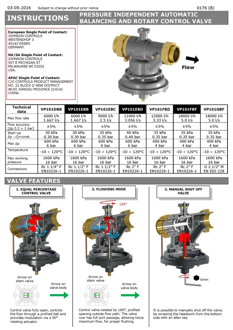
Johnson Controls VP101DBB instructions
Telcoma
Telcoma K100 Instructions for installing

Renishaw
Renishaw A-2028-7574 installation guide
Rosani
Rosani Classic SW736619 User manual/instructions

MS Schippers
MS Schippers SC-01 manual
National Instruments
National Instruments Module SCXI-1125 CALIBRATION PROCEDURE
