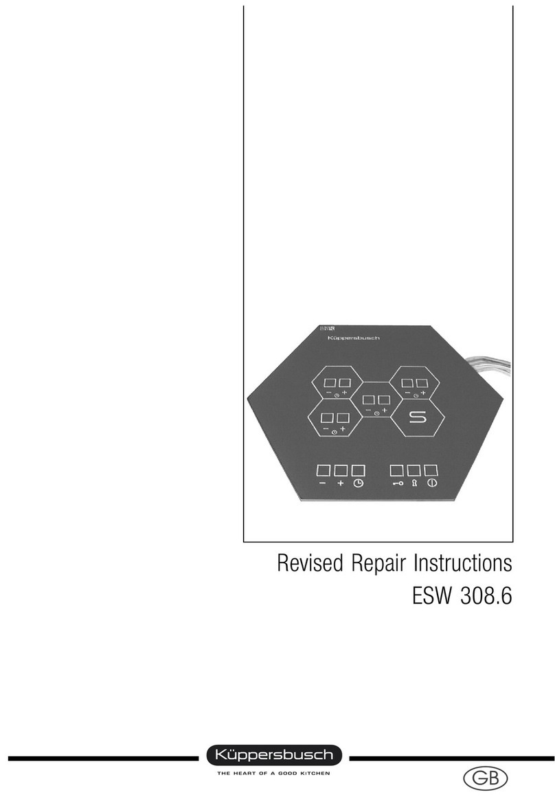
Kuppersbusch ESW 307.6 User manual

KÜPPERSBUSCH
After-Sales Service
Technical Manual
ESW 307.6 / EKW 306.0 /
EKW 306.1
GB

Table of Contents
1 Introduction and Safety Advisory 1
2 Tools and Aids 2
3 Function Description 3
3.1 Sensor operation for the control panel 3
3.2 Switching on 5
3.3 Switching off 5
3.4 The cooking levels 5
3.5 Cooking without auto parboil 5
3.6 Cooking with auto parboil 6
3.7 Switching off the cook levels 6
3.8 Dual-circuit zones EKW 306.1 6
3.9 Switching off the dual zone 6
3.10 The central switch-off 7
3.11 Child safety function (sensor lockout) 7
3.12 Other functions 8
4 Electrical connections 8
4.1 Connecting cooking element to cooking control 8
4.2 Connector 9
4.3 Mains 9
5 Error diagnostics 10
6 Components of the ESW 307.6 11
7 Disassembling the individual components 12
7.1 Disassembling the control 12
7.2 Disassembling the mains supply NE01 13
7.3 Disassembling the power unit LE01 14
7.4 Disassembling the control board 15
8 Calibrating the sensor electronics 16
VKS-H Technical Manual
ESW 307.6 / EKW 306.0 / EKW 306.1 H1-58-01
Responsible: D. Rutz Phone.: (0209) 401-733 Fax: (0209) 401-743 Date: 4.06.1997
1For internal use only

1 Introduction and safety advisory
The ESW 307.6 is a photosensor-based control. This is designed to permit non-contact control of
the cooking elements.
These documents are intended as an accompanyment for practical training of the customer service
technician.
SAFETY ADVISORY
These devices are constructed in accordance with relevant safety regulations.
Mains connection, maintenance and repair of these devices are to be carried out only by an authori-
zed specialist following the relevant safety regulations. Improperly performed work will endanger
your safety.
Before opening the unit, the mains must be disconnected!
Further General Recommendations can be found in the Guide for Use and Assembly for Cooktops
with Sensor Control Series ESW / EKW.
VKS-H Technical Manual
ESW 307.6 / EKW 306.0 / EKW 306.1 H1-58-01
Responsible: D. Rutz Phone.: (0209) 401-733 Fax: (0209) 401-743 Date: 4.06.1997
For internal use only 2

2 Tools and Aids
The following tools are required for problemless customer service:
·
Digital multimeter incl. measuring probes
·
Battery powered or gas soldering iron
·
Solder
·
Small ratchet assortment
·
5.5 mm socket spanner (Belzer No. 6400-5.5)
·
8.0 mm socket spanner
·
Flat screwdriver with a blade of max. 1.6 x 0.5 mm (for adjusting pots)
·
Small sidecutters
·
Small flat nose pliers
·
Tweezer assortment
·
Flat screwdrivers, various sizes (very important: with short grips)
·
Phillips screwdrivers, various sizes (very important: with short grips)
·
Torch, angled
·
Small pocket mirror
In addition, the following aids are required :
·
Power supply for calibration
·
Adjusting angle for calibrating photosensors
·
Glass cleaner, Sidolin or similar
·
Cleaning cloths
VKS-H Technical Manual
ESW 307.6 / EKW 306.0 / EKW 306.1 H1-58-01
Responsible: D. Rutz Phone.: (0209) 401-733 Fax: (0209) 401-743 Date: 4.06.1997
3For internal use only

3 Function description
3.1 Sensor operation with the control panel
Since the number and location of the honeycomb units can be individually determined, the control
units must be adapted to the arrangement of the honeycomb unit configuration which you have se-
lected. You may use your creativity here. The markings on the control unit correspond to the arran-
gement of the honeycomb units on the hob, so as to make operation as intuitive as possible.
A control unit can operate up to 6 honeycomb units. Should more than 6 honeycomb units be con-
nected in a system, a second control unit is required. The control function of the controller always
includes also control of the dual-circuit cooking zone and auto cook, as well as the child safety fea-
ture which locks out the electronics.
AKey-sensor and
BLock sensor for the childproof lock
CControl panels for the honeycomb units with
Plus and Minus sensors (example configu-
ration)
DCentral OFF sensor
EThis panel has no switching function.
It simply indicates the position of the
control unit.
VKS-H Technical Manual
ESW 307.6 / EKW 306.0 / EKW 306.1 H1-58-01
Responsible: D. Rutz Phone.: (0209) 401-733 Fax: (0209) 401-743 Date: 4.06.1997
For internal use only 4

3.2 Turn on
Hold down the central OFF sensor for ca. 2 seconds.
A vertical bar between the central OFF sensor and the
childproof lock illuminates.
The appliance is ready (stand-by mode).
3.3 Turn off
Briefly (ca. 0.3 seconds) press the central OFF sensor.
The control unit automatically switches itself off again if:
- no other sensor is pressed within 20 seconds*,
- the control unit remains unused after 10 minutes of
operation, or
- a cooking zone sensor is pressed for longer than 20
seconds*.
* After 10 seconds an acoustic warning signal indicates
that the unit will shut itself off after 10 more seconds
have elapsed.
3.4 The cooking levels
There are 9 cooking levels (1-9). The cooking levels are
indicated in the display for the respective cooking zone.
The desired level can be selected using the Plus sensor
(cooking without auto parboil) or the Minus sensor (coo-
king with auto parboil). There is no null position.
All cooking zones have an auto parboil function availa-
ble.
3.5 Cooking without auto parboil
Press the Plus sensor. The cooking zone starts at Level
5. Now select the desired cooking level.
VKS-H Technical Manual
ESW 307.6 / EKW 306.0 / EKW 306.1 H1-58-01
Responsible: D. Rutz Phone.: (0209) 401-733 Fax: (0209) 401-743 Date: 4.06.1997
5For internal use only

3.6 Cooking with auto parboil
Press the Minus sensor. The cooking zone starts at Le-
vel 9, and the auto parboil function is activated. Now
switch down to the desired cooking level. After the auto
parboil function is completed, the cooking zone switches
over to the desired cooking level.
During auto mode, the display flashes ”A” alternating
with the preset cooking level.
One can still switch back and forth between the indivi-
dual cooking levels; the remaining time for the auto par-
boil is carried over.
3.7 Switch off the cooking levels
Press the Plus and Minus sensors simultaneously for
ca. 3.5 seconds.
Hold the Minus sensor down. The cooking levels are
counted down. After cooking level 1 the cooking zone
goes off.
3.8 Dual-circuit cooking zones EKW 306.1
Dual-circuit zones are indicated by a blinking dot in the
associated display.
Hold down the Plus and Minus sensor simultaneously
for ca. 1 second. The indicator light next to the display
for the cooking level comes on and an acoustic signal is
generated.
3.9 Switch off the dual-circuit zone
Hold down the Plus and Minus sensor simultaneously
for ca. 1 second.
The indicator light goes out and an acoustic signal is
generated to indicate that the dual-circuit zone is off.
VKS-H Technical Manual
ESW 307.6 / EKW 306.0 / EKW 306.1 H1-58-01
Responsible: D. Rutz Phone.: (0209) 401-733 Fax: (0209) 401-743 Date: 4.06.1997
For internal use only 6

3.10 The central OFF function
The central OFF sensor can be used to immediately
turn off all functions independent of each other.
3.11 Child safety feature
(sensor lockout)
The sensor lockout can be used to prevent unauthorized
use of the device. Disable the hob as follows:
Press the key sensor until an acoustic signal is heard.
Then press the lock sensor until an acoustic signal is
heard.
Lockout status is indicated by 3 horizontal bars in the
stand-by display.
To unlock the cooking hob:
Press the key sensor until an acoustic signal is heard.
VKS-H Technical Manual
ESW 307.6 / EKW 306.0 / EKW 306.1 H1-58-01
Responsible: D. Rutz Phone.: (0209) 401-733 Fax: (0209) 401-743 Date: 4.06.1997
7For internal use only

Then press the lock sensor until an acoustic signal is
heard.
Unlock status is indicated by a vertical bar in the stand-
by display. Sensor lockout remains in effect even after
the system is turned off. It is also unaffected by presen-
ce or absence of mains power.
3.12 Additional functions
Pressing two or more sensors at the same time, e.g. if a
pot is accidentally placed against the sensors, does not
generate a switching function. After 10 seconds an audi-
ble signal is heard, and after 20 seconds the entire elec-
tronics is shut off. Exceptions:
- Disabling the sensor lockout
- Switching dual-circuit zone on or off
- Switching off cooking zones.
If a sensor is actuated after reaching the highest level, a
signal is heard after 10 seconds, and after 20 seconds
the entire electronics is shut off.
There is no automatic start-up after a power loss.
4 Electrical connection
4.1 Connecting honeycomb element to
control unit
A control unit can handle up to 6 honeycomb elements.
Up to 3 EKW 306.1 dual-circuit cooking zones can be
connected to one control unit.
VKS-H Technical Manual
ESW 307.6 / EKW 306.0 / EKW 306.1 H1-58-01
Responsible: D. Rutz Phone.: (0209) 401-733 Fax: (0209) 401-743 Date: 4.06.1997
For internal use only 8

Follow the wiring diagram exactly when making
connections!
A wiring diagram is included with the ESW 307.6 control
unit, with a number corresponding to each honeycomb
element. These numbers are also found on the wiring
guide for the honeycomb element. This allows you to
easily determine which sensors control which honey-
comb elements.
4.2 The connector
for the EKW 306.1 cooking zone has 3 connections
for the EKW 306.1 dual-circuit cooking zone has 4
connections
The connections are marked on the plugs
(N / L1 / L2 / etc.)
4.3 Connecting the mains
This connection must be made by trained personnel.
Standard good electrical practice as well as any regula-
tions of the local electricity provider must be strictly ob-
served.
The control must have no voltage to it during assembly.
Open the isolation device on the installation side.
Insert the compact plug for the control into its mate on
the connection side.
Connected load: 400 V 3N~ 50 Hz
Power consumption: max 8.7 kW
Using single-phase mains supply is only possible if ma-
ximum two single- and one dual-circuit elements are
connected.
VKS-H Technical Manual
ESW 307.6 / EKW 306.0 / EKW 306.1 H1-58-01
Responsible: D. Rutz Phone.: (0209) 401-733 Fax: (0209) 401-743 Date: 4.06.1997
9For internal use only

5 Error diagnostics
ESW 307.6 functions incorrectly
ESW 307.6 can be turned on with finger ESW 307.6 turns on, but cooking
zone does not heat Sensor defective Replace control board
ESW 307.6 can be turned
on with mirror Yes Replace complete
control Sensor OK
Check all phases Phase missing Turn on automatic fuse
NO
Check mains voltage No voltage Check automatic fuse or
connection Voltages OK
OK Check element with calibration
powwer supply Cooking zone defective Replace cooking zone
Open ESW 307.6 and check power
supply fuse Fuse defective Change fuse Cooking zone OK
OK Power board defective Replace power board
Power supply defective
Defective Replace regulator
OK Calibrate sensor, see repair note Point 6
Check voltage regulator (with
calib.) power supply
Replace power supply
VKS-H Technical Manual
ESW 307.6 / EKW 306.0 / EKW 306.1 H1-58-01
Responsible: D. Rutz Phone.: (0209) 401-733 Fax: (0209) 401-743 Date: 4.06.1997
For internal use only 10

6 ESW 307.6 components
LE01 power unit
NE01 power supply
Control
VKS-H Technical Manual
ESW 307.6 / EKW 306.0 / EKW 306.1 H1-58-01
Responsible: D. Rutz Phone.: (0209) 401-733 Fax: (0209) 401-743 Date: 4.06.1997
11 For internal use only

7 Disassembling the individual components
7.1 Disassembling the control
Before opening the unit, please read the safety
advisory!
To remove the housing cover, the screws
marked with an X must be unscrewed.
After removing the screws, set the cover
carefully aside.
VKS-H Technical Manual
ESW 307.6 / EKW 306.0 / EKW 306.1 H1-58-01
Responsible: D. Rutz Phone.: (0209) 401-733 Fax: (0209) 401-743 Date: 4.06.1997
For internal use only 12

7.2 Disassembling the NE01 power supply
To disassemble the NE01 power supply,
the connectors must first be removed (the
connectors cannot be reversed when reas-
sembling, since they all have different num-
bers of pins.).
Finally, a 5.5 mm socket spanner can be
used to remove the nuts on the power
supply.
Now the power supply can be removed
from the housing.
To reassemble, follow the above steps in
reverse order.
VKS-H Technical Manual
ESW 307.6 / EKW 306.0 / EKW 306.1 H1-58-01
Responsible: D. Rutz Phone.: (0209) 401-733 Fax: (0209) 401-743 Date: 4.06.1997
13 For internal use only

7.3 Disassembling the LE01 power unit
When removing the power unit, have a new
unit ready and at hand.
The electrical connections to the power unit
are removed one by one and reconnected
to the new unit in the same positions.
Do not reverse any of the electrical leads!
After the new connections are made, use a
5.5 mm socket spanner to remove the po-
wer unit nuts and remove the circuit board.
Now insert the new power unit into the hou-
sing and close it up.
LE01 power unit
VKS-H Technical Manual
ESW 307.6 / EKW 306.0 / EKW 306.1 H1-58-01
Responsible: D. Rutz Phone.: (0209) 401-733 Fax: (0209) 401-743 Date: 4.06.1997
For internal use only 14

7.4 Disassembling the control board
The control board can only be disassem-
bled after the NE01 power supply and
LE01 power unit have been removed.
Finally, remove the 3 mounting screws
from the control board. The circuit board is
removed by lining up the cutout with one of
the upper mounting brackets. Then remove
it by lifting upwards.
Insert the new circuit board and fasten it
using the 3 screws.
Use the torch to illuminate the circuit board
from behind. Now the position of the indivi-
dual components can be checked from
above.
Should the photosensors and the imprint
on the Ceran disc not coincide, the circuit
board must be loosened again in order to
bring it into the correct position. When the
photosensors match the position of the im-
print on the Ceran disc, the 3 screws can
be tightened down.
VKS-H Technical Manual
ESW 307.6 / EKW 306.0 / EKW 306.1 H1-58-01
Responsible: D. Rutz Phone.: (0209) 401-733 Fax: (0209) 401-743 Date: 4.06.1997
15 For internal use only

8 Calibrating the sensor electronics
Aids: Adjusting angle for sensor electronics
Power supply for calibration
- The power supply is now electrically connected to the
control board.
- Turn all potentiometers to full CCW position.
- Clean Ceran disc with glass cleaner.
-Start with the ”ON-OFF” sensor. Set the adjusting angle
from above on the Ceran disc on the corresponding mo-
dule. Now turn the potentiometer slowly CW until the
electronics turns on as indicated with the audible tone.
- After the angle adjustment, the sensor should be te-
sted again using your finger, i.e. the sensor should re-
spond at a height of ca. 1 cm.
- Turn one sensor pot to the ”11 o’clock” position.
- Turn the control on again and touch the previously
calibrated sensor directly with the finger, then calibra-
te again using the adjusting angle!
- Next, calibrate all cooking zone sensors in the same
way.
- Finally, the ”key-lock” combination is set. First set the
key sensor as described earlier. Note that there is a
short delay time until the acoustic signal comes on,
i.e. the switchpoint must be very slowly searched with
the potentiometer.
- The lock sensor can be set using the key sensor. Hold
the setting angle on the lock sensor, use your finger to
hold and activate the key sensor until the acoustic si-
gnal is heard. Now you must immediately begin adjust-
ment of the pots, since only 2 seconds are available for
this procedure. The process must be repeated, since
the switchpoint will not be found immediately. This
switchpoint
must however be hit exactly, since improper
function will result otherwise.
At the conclusion of the setting procedure, test each
sensor again using your finger.
Assemble by following the steps described in the pre-
vious pages in reverse order.
VKS-H Technical Manual
ESW 307.6 / EKW 306.0 / EKW 306.1 H1-58-01
Responsible: D. Rutz Phone.: (0209) 401-733 Fax: (0209) 401-743 Date: 4.06.1997
For internal use only 16
This manual suits for next models
2
Table of contents
Other Kuppersbusch Control Unit manuals