6 H1-58-01-02-Ä
For internal use only
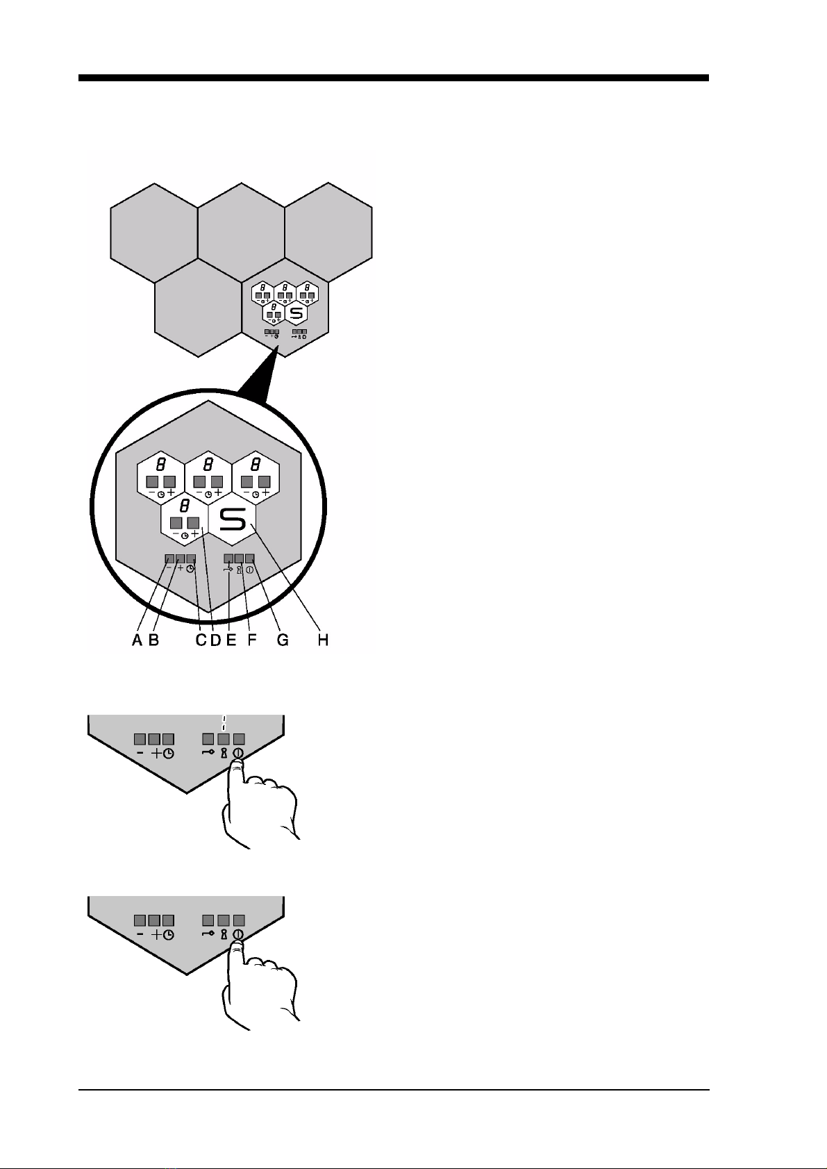
4. Functional Description of the Honeycomb Control Unit
The honeycomb cooking zone is equipped with a
convenient sensor control unit which is regulated by
means of the control honeycomb.
The markings in the honeycomb control unit repeat
the layout of the cooking zones on the worktop.
With the honeycomb control unit you can also
control
• the cooking with auto parboil
• the minute minder
• the childproof lock
The following control fields are on the honeycomb
control unit:
A and B are control fields for the minute minder with
Plus and Minus sensors
C = Minute Minder
D = Control fields for the cooking zones with Plus
and Minus sensors.
E = Key sensor for childproof lock
F = Lock sensor for childproof lock (Sensor-lock).
G = On / Off sensor
H = This field has no control functions. It simply
indicates the position of the honeycomb control unit.
Switching on and off the appliance
Switching on
Touch the ON-OFF sensor for about 2 seconds. A vertical
bar will light up above the lock sensor.
The appliance is now ready to be put into operation (standby
mode). Each cooking zone can now be controlled
individually.
Switching all functions off
Briefly touch the ON-OFF sensor (for about 0.3 seconds).
The vertical bar will be extinguished. The control honeycomb
unit switches off again automatically, if no further sensor is
touched within 20 seconds, if it is left unused for 10 minutes
after operation or if the sensor of a cooking zone is touched
for longer than 20 seconds.
An acoustic signal already sounds after 10 seconds to warn
you that the appliance will switch off after another
10 seconds.
2 secs.
0.3 sec.