04
www.kusauto.com
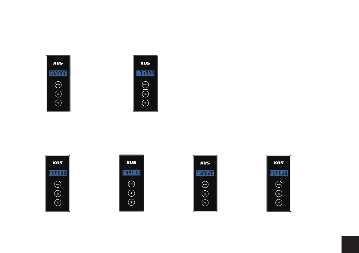
NMEA2000 J1939
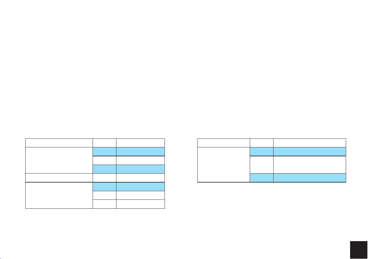
Value
00/10/20/30
01/11/21/31
02/12/22/32
03/13/23/33
04/14/24/34
05/15/25/35
06/16/26/36
07/17/27/37
08/18/28/38
09/19/29/39
Sensor Type
Fuel level
Fresh water level
Waste water level
Live Well level
Oil level
Black Water level
Oil press(0~5Bar,10~185Ω)
Oil press(0~10bar, 10~185Ω)
Coolant temp(40~120℃,300~23Ω)
Oil temp(50~150℃,300~23Ω)
Value
00/10/20/30
01/11/21/31
02/12/22/32
03/13/23/33
04/14/24/34
05/15/25/35
06/16/26/36
07/17/27/37
Sensor Type
Fuel level
Washer Fluid level
engine coolant level
engine oil level
Coolant temp(40~120℃,300~23Ω)
Oil temp(50~150℃,300~23Ω)
Oil press(0~5Bar,10~185Ω)
Oil press(0~10bar, 10~185Ω)
The values specific to product
3.2.3 Instance (Number) setting
In Instance query interface, long press MODE key
until LCD flashes and release; Use UP/DOWN to
set Instance(number); Long press MODE key
again until LCD stops flashing.
Setting completed
3.2.4 Signal type setting
3.2.4.1 Commonly used resistance signal setting
In signal type query interface, long press MODE key until LCD flashes and release.
Use UP/DOWN to set signal type, Long press MODE key again until LCD stops
flashing.
Setting completed
Instance Signal type
Value
00
Resistance signal
240~33Ω
Values specific to signal
01
02
SEF
0~190Ω
10~180Ω
Self-defined
0A/1A/2A/3A Rudder