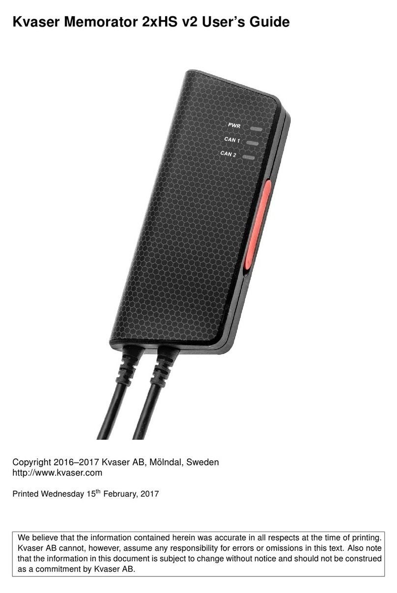
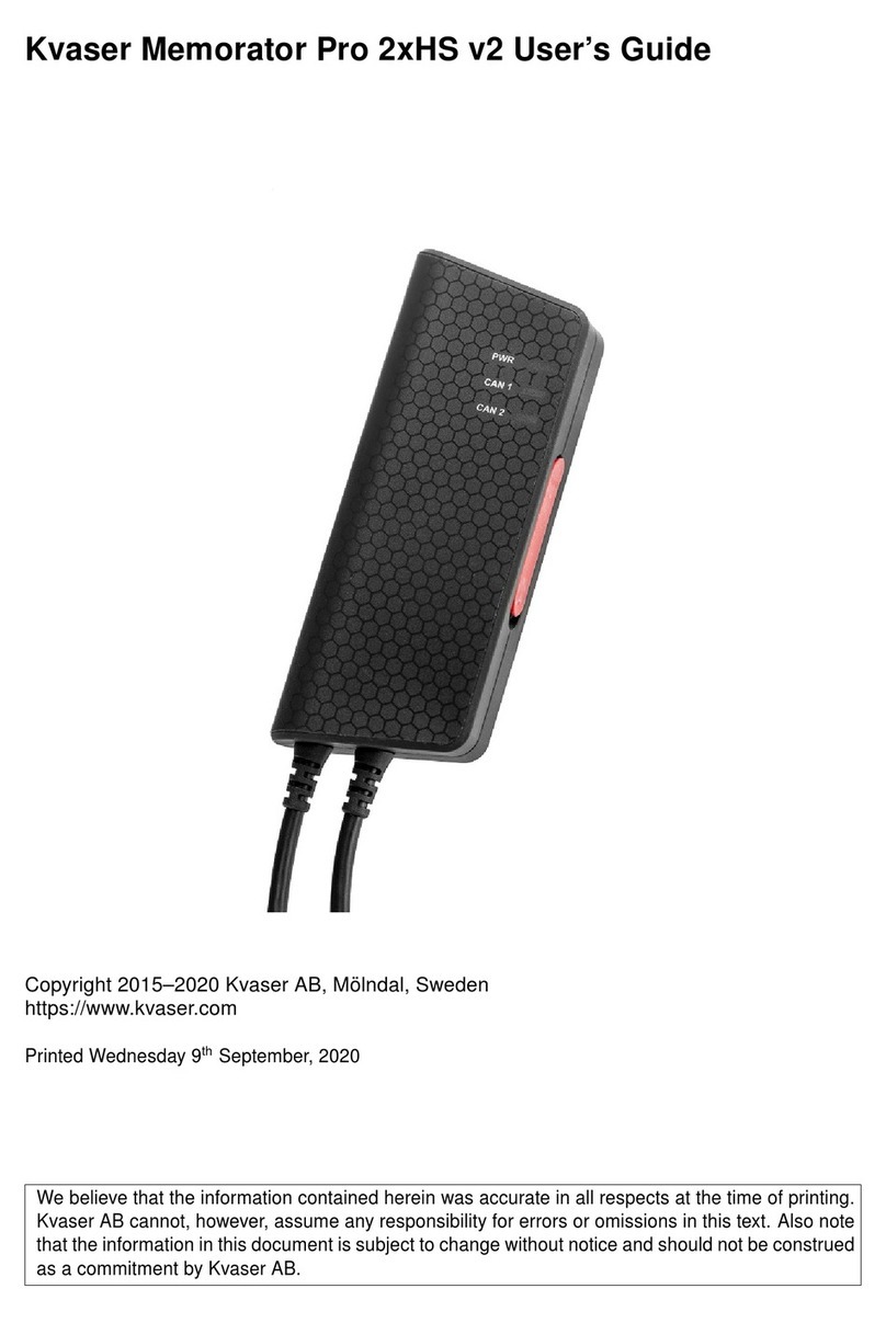
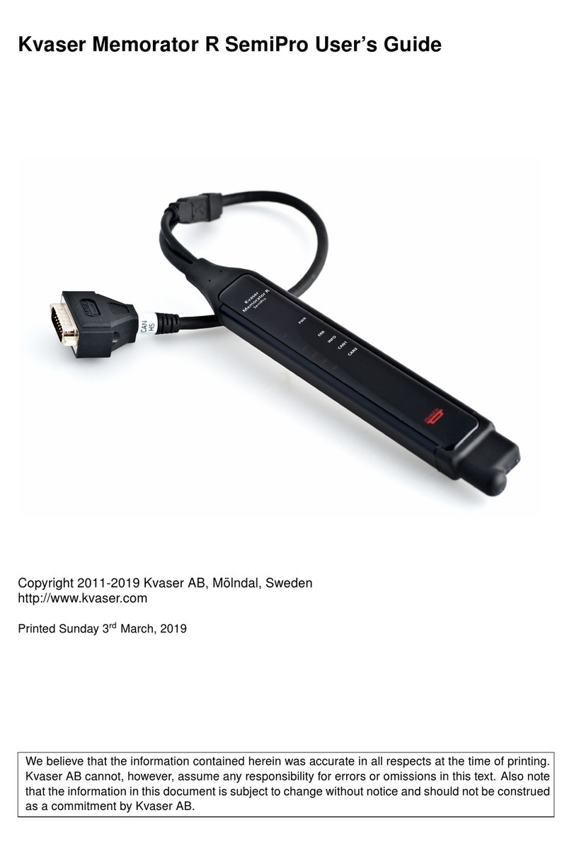
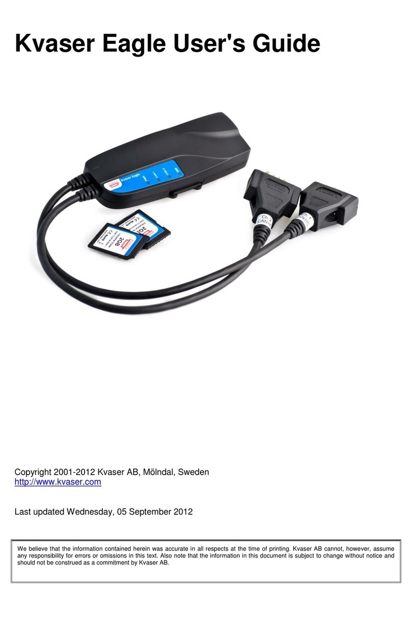
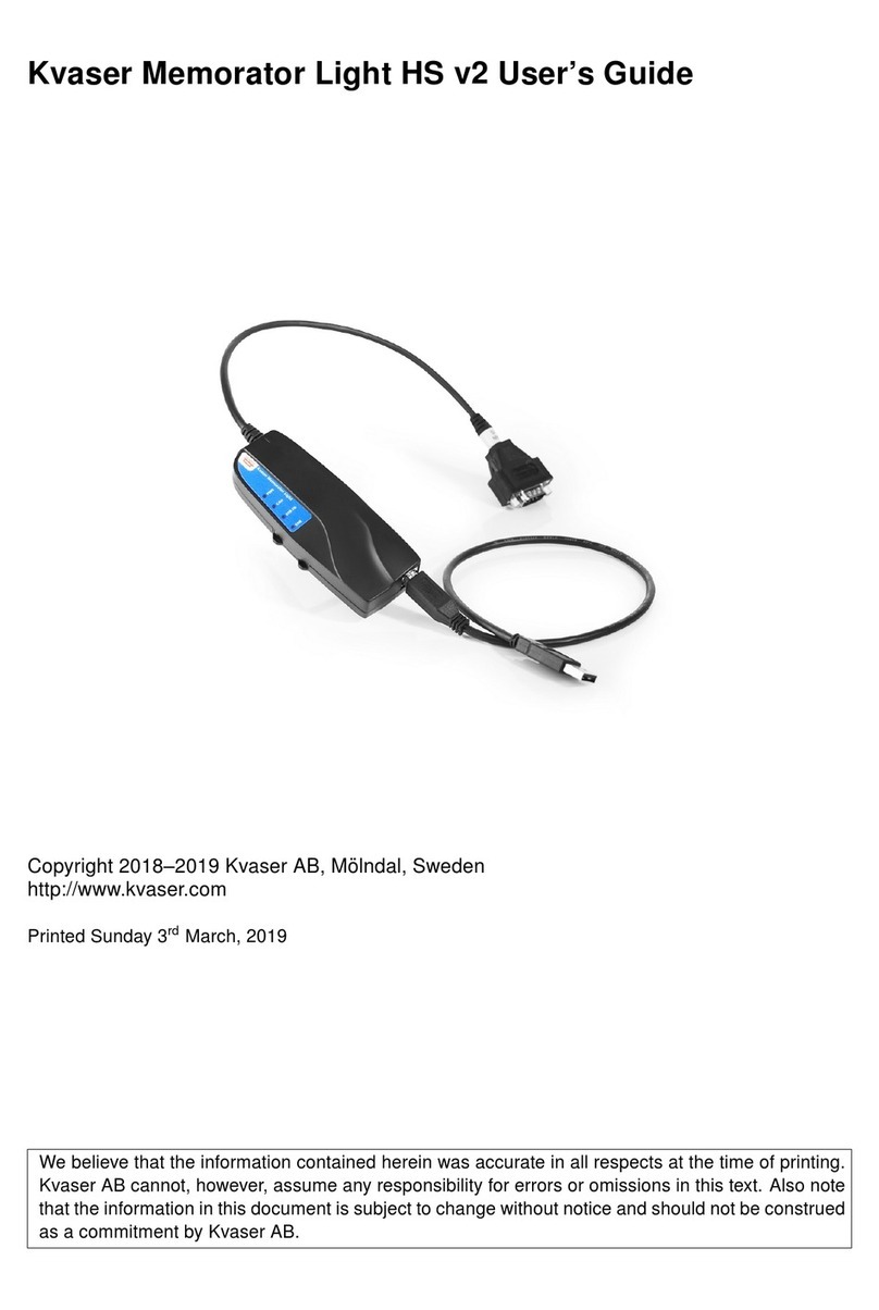
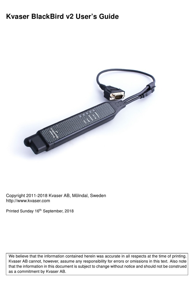
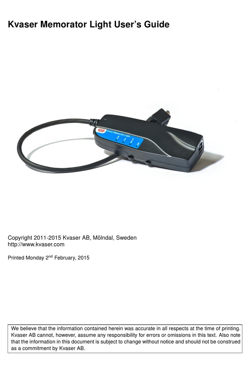
Kvaser Memorator R SemiPro User manual

Kvaser Memorator R SemiPro
User's Guide
Copyright 2001-2011 Kvaser AB, Mölndal, Sweden
http://www.kvaser.com
Last updated Monday, 19 September 2011

We believe that the information contained herein was accurate in all respects at the time of printing. Kvaser AB cannot, however, assume
any responsibility for errors or omissions in this text. Also note that the information in this document is subject to change without notice and
should not be construed as a commitment by Kvaser AB.

Kvaser Memorator R SemiPro User's Guide 3(31)
Kvaser AB, Mölndal, Sweden —www.kvaser.com
(This page is intentionally left blank.)

Kvaser Memorator R SemiPro User's Guide 4(31)
Kvaser AB, Mölndal, Sweden —www.kvaser.com
1 Table of Contents
Kvaser Memorator R SemiPro User's Guide..........................................................................1
1Table of Contents..............................................................................................................4
2About this manual .............................................................................................................5
3Introduction........................................................................................................................6
3.1 Welcome to Kvaser Memorator R SemiPro.................................................................6
3.2 Major features of Kvaser Memorator R SemiPro.........................................................7
3.3 CAN logger Functions..................................................................................................7
3.4 Real time CAN-USB interface......................................................................................8
3.5 Kvaser Memorator Tools..............................................................................................8
3.6 Additional software and documentation.......................................................................8
4Kvaser Memorator R SemiPro Hardware........................................................................9
4.1 Hardware installation....................................................................................................9
4.2 USB connector.............................................................................................................9
4.3 CAN channels ..............................................................................................................9
4.4 Power supply............................................................................................................. 10
4.5 Flash disk.................................................................................................................. 10
4.6 LED indicators........................................................................................................... 10
4.7 External trigger input................................................................................................. 14
4.8 External trigger output............................................................................................... 15
5How to use the Kvaser Memorator R SemiPro............................................................ 17
5.1 Use as a CAN interface............................................................................................. 17
5.2 Configure for logging................................................................................................. 17
5.3 Use as a logger......................................................................................................... 17
5.4 Kvaser Memorator Tools........................................................................................... 17
5.5 Troubleshooting ........................................................................................................ 18
6Appendices ..................................................................................................................... 19
6.1 System requirements ................................................................................................ 19
6.2 Technical data........................................................................................................... 19
6.3 Performance.............................................................................................................. 21
6.4 Disk capacity............................................................................................................. 21
6.5 CAN connectors........................................................................................................ 21
6.6 Updating the firmware............................................................................................... 24
6.7 Required software versions....................................................................................... 25
6.8 CAN bus termination................................................................................................. 25
6.9 CAN bus overrun....................................................................................................... 26
6.10 Daisy-chaining several interfaces.......................................................................... 26
7Frequently Asked Questions......................................................................................... 27
8Disposal and Recycling Information............................................................................ 28
9Legal acknowledgements.............................................................................................. 29
9.1 Usage warning .......................................................................................................... 29
9.2 EMC compliance statement...................................................................................... 30
9.3 RoHS compliance statement..................................................................................... 30
9.4 Patents, copyrights and trademarks ......................................................................... 30
10 Document revision history ........................................................................................ 31
Kvaser Memorator R SemiPro User's Guide 5(31)
Kvaser AB, Mölndal, Sweden —www.kvaser.com
2 About this manual
This manual is intended for Kvaser Memorator R SemiPro users. This manual contains a
description of the hardware’s properties and general instructions for connecting the device to
a computer. The setup software for the Kvaser Memorator R SemiPro is called Kvaser
Memorator Tools and is described in detail in its online help.

Kvaser Memorator R SemiPro User's Guide 6(31)
Kvaser AB, Mölndal, Sweden —www.kvaser.com
3 Introduction
This section will describe the functions and features of the Kvaser Memorator R SemiPro.
3.1 Welcome to Kvaser Memorator R SemiPro
Figure 1. Kvaser Memorator R SemiPro
Kvaser Memorator R SemiPro is a small, yet advanced portable CAN data logger. The
device can be configured in many different ways to achieve the most suitable and effective
logging for any occasion. Connecting the logger to a PC provides direct access for
configuring baud rates, trigger conditions, and filters using the standalone Kvaser Memorator
Tools. To achieve a rugged design, the SD-disk is located inside the unit and soldered to the
PCB. This ensures error free operation even when exposed to vibration and shock.
The Kvaser Memorator R SemiPro can also be used as a powerful two channel real time CAN
to USB interface –two products in one!
An additional advantage of the Kvaser Memorator R SemiPro is ability to log J1587 traffic by
connecting the Kvaser Linx J1587. With a combination of the Kvaser Linx J1587 and the
Kvaser Memorator R SemiPro, you get an even more powerful and versatile data logger.
3.1.1 Triggers
You can setup the Kvaser Memorator R SemiPro to log continuously, or you can create
triggers to control when frames are logged. You can create up to 16 trigger conditions.
These conditions can include the reception of a specific message, the value of a specific
signal in a message, or an external trigger input’s rising or falling edge. You can define a
post-trigger time to control the amount of data logged after the trigger expression becomes
false, and/or a pre-trigger time to log events leading up to the trigger expression becoming
true.

Kvaser Memorator R SemiPro User's Guide 7(31)
Kvaser AB, Mölndal, Sweden —www.kvaser.com
3.1.2 Filters
To enhance logging performance, the Kvaser Memorator R SemiPro can filter out selected
messages. The identifiers to be filtered can be picked from a database file or entered
manually. Three types of filters are provided: stop filters, pass filters, and counting pass
filters. Stop filters prevent messages from being logged. Pass filters ensure a message is
logged. Counting pass filters log the specified messages at enumerated occurrences so
redundant data is reduced.
3.1.3 Memory card
To achieve a rugged and robust product, the memory card (a SD disk) is placed inside the
shell and cannot be replaced.
3.2 Major features of Kvaser Memorator R SemiPro
CAN interface and data logger –two products in one.
Quick and easy plug-and-play installation.
Supports both 11-bit (CAN 2.0A) and 29-bit (CAN 2.0B active) identifiers.
CAN messages are time-stamped with a 2 microsecond resolution.
Large on-board RAM buffer for CAN messages.
Supports silent (listen-only) mode for analyzing tools and data logging.
100% compatible with applications written with Kvaser CANLib for other Kvaser
hardware such as LAPcan, PCIcan, and USBcan.
Two high-speed CAN channels (compliant with ISO 11898-2), 10 kbit/s up to 1 Mbit/s.
Fully compatible with J1939, CANopen, NMEA 2000® and DeviceNet.
One USB 2.0 HiSpeed connection with data rates up to 480 Mbit/s. The device can
also be used in USB 1.1 slots (with up to 12 Mbit/s).
Power is taken from the CAN bus or from the USB bus. The device automatically
switches power supply between the CAN (primary) and the USB (secondary),
reducing power drain on a laptop’s battery.
Small, light aluminum housing with approximate dimensions 31 x 220 x 19 mm (1.2 x
8.7 x 0.8 inches) (W x L x H) –easy to tuck away (e.g. in a vehicle during a test
drive).
The CAN-cable is 40 cm (16 inches).
The USB cable is 10 cm (4 inches).
3.3 CAN logger Functions
One fixed 4GB memory card.
Built-in real time (calendar) clock with battery backup.
Easy to use graphic configuration tool.
Logger status is indicated with five externally visible LEDs.
Supports silent mode –you can log bus traffic without interfering with the bus.
Handles 100% bus load at 1 Mbit/s with two channels (>20000 messages per
second).
Starts up in 500 milliseconds.
Upload logged data via USB at 1.2 MB/s when connected via USB 2.0 HiSpeed.
External trigger input (e.g. pushbutton).
External trigger output (e.g. a LED or buzzer).
Pre-trigger space is limited by available disk space only.

Kvaser Memorator R SemiPro User's Guide 8(31)
Kvaser AB, Mölndal, Sweden —www.kvaser.com
Select trigger signals from a CAN database or define them directly in the Kvaser
Memorator Tools.
3.4 Real time CAN-USB interface
Uses USB 2.0 HiSpeed, while maintaining compatibility with USB 1.x computers.
Supports extreme data throughput, quick reaction times and precise time stamping –
removing any bottlenecks. Handles up to 40 000 messages per second.
Kvaser MagiSync- automatic time synchronization between all Kvaser products
that uses the Kvaser MagiSyncfeature.
Supports silent mode for analyzing tools –listen to the bus without interfering with
traffic.
Simultaneous operation of multiple devices.
Power supplied through the CAN bus interface or through the USB interface.
3.5 Kvaser Memorator Tools
Easy to use graphic configuration tool.
File manager for organizing and converting log files to a variety of formats including
CSV, ASCII, MDF, and Matlab formats.
Configuration of the CAN controller (bit rate, sample point, etc.).
Configuration of the trigger conditions.
Configuration of message filters which control the messages stored.
The configuration is downloaded via USB.
3.6 Additional software and documentation
The Kvaser CANLIB SDK includes everything you need to develop software for
Kvaser CAN hardware. Includes full documentation and many sample programs
written in C, C++, C#, Delphi, and Visual Basic. All Kvaser CAN interface hardware
shares a common software API. Programs written for one board type can run without
modification on the other board types.
On-line documentation in Windows® HTML Help format.
Documentation, software, and drivers can be downloaded for free at
www.kvaser.com.

Kvaser Memorator R SemiPro User's Guide 9(31)
Kvaser AB, Mölndal, Sweden —www.kvaser.com
4 Kvaser Memorator R SemiPro Hardware
In this section you can read more about the CAN channels, power supply, flash disk, LED
indicators, and external triggers.
4.1 Hardware installation
The Kvaser Memorator R SemiPro may be inserted in any free USB socket on the host
computer. You do not need to switch the power off before inserting or removing the device.
For the Kvaser Memorator R SemiPro to communicate with the host computer, the correct
version of the Kvaser driver and firmware must be installed. The firmware is downloaded and
installed directly on the Kvaser Memorator R SemiPro and the driver is installed on the host
computer. For additional information on how to upgrade the firmware, read section 6.6
Updating the firmware.
The Kvaser Memorator R SemiPro delivery package contains:
Kvaser Memorator R SemiPro.
Software and Driver CD which contains drivers for Windows; Kvaser Memorator
Tools; Kvaser CANKing, an easy to use CAN bus monitor; Drivers for RP1210A,
LabView and DIAdem; and Kvaser CANlib Software Development Kit.
Kvaser Memorator R SemiPro User's Guide.
Adapter cable for a 15 pin DSUB to 2 x 9 pin DSUB
For driver installation information, see the driver and hardware installation guide which can be
found at http://www.kvaser.com.
4.2 USB connector
The Kvaser Memorator R SemiPro has a standard USB type ―A‖ plug connector. Connect the
unit to your PC directly or by using any high quality USB 2.0 certified cable. The maximum
USB cable length is 4.5 meters (approx. 165 ft.). If you need a longer cable, you can use
USB hubs or USB extension cables with a built-in hub.
4.3 CAN channels
The standard Kvaser Memorator R SemiPro has two independent CAN channels in the 15 pin
DSUB shown in Figure 2. The product comes with an adapter cable to split the two channels
into two separate connectors if necessary. The CAN connectors in the adapter cable are also
labeled for easy identification.

Kvaser Memorator R SemiPro User's Guide 10(31)
Kvaser AB, Mölndal, Sweden —www.kvaser.com
CAN channels
connector
USB device
connector
Figure 2. Connectors on the Kvaser Memorator R SemiPro. The two CAN channels are
in the 15 pin DSUB on the right and the USB device connector is on the left.
4.4 Power supply
The Kvaser Memorator R SemiPro can be powered through the CAN connector and through
the USB connector. To operate the Kvaser Memorator R SemiPro in logger mode, you must
supply power through the CAN connector.
When you supply power on the CAN connector, provide power on channel 1. When using the
adapter cable, use pin 9 for V+ and pin 3 for ground on the CAN1 connector. When
connecting directly to the 15 pin DSUB, use pin 9 for V+ and pin 1 for ground.
The supply power should be in the range of 6 –35 V DC. The power requirement is around 1
W (maximum). Supplying power on CAN2 is safe, but pointless. The device will tolerate
higher input voltages, up to 48 V DC.
To use the device as a CAN interface or to configure the device for logging, power supplied
through the USB connector is sufficient.
4.5 Flash disk
Due to the high demands placed on a rugged, industrial product such as the Kvaser
Memorator R SemiPro, the memory card is fixed and sealed inside the unit. The card meets
necessary performance requirements including industrial temperature range.
The selected size of 4 GB should cover most cases. This size provides a balance between
duration logging and overly large logs which are cumbersome to analyze.
4.6 LED indicators

Kvaser Memorator R SemiPro User's Guide 11(31)
Kvaser AB, Mölndal, Sweden —www.kvaser.com
The LED indicators (see Figure 3) have somewhat different meaning depending on how the
Kvaser Memorator R SemiPro is being used –as a CAN interface or as a CAN logger. The
following tables describe how the LEDs behave in these two cases.
In the tables, ―slow flash‖ means a frequency around 0.5 Hz, and ―fast flash‖ means a
frequency of around 2 Hz.
Table 1: LED indicators overview
LED
General meaning
PWR (Green)
Power and general status.
ERR (Red)
Indicates permanent errors.
INFO (Orange)
Indicates temporary errors.
CAN 1 (Yellow)
Status for CAN channel 1.
CAN 2 (Yellow)
Status for CAN channel 2.
Figure 3. LEDs on the Kvaser Memorator R SemiPro.

Kvaser Memorator R SemiPro User's Guide 12(31)
Kvaser AB, Mölndal, Sweden —www.kvaser.com
Table 2: LED indicators when used as a CAN interface
PWR
(Green)
CAN 1
(Yellow)
CAN 2
(Yellow)
ERR
(Red)
INFO
(Orange)
Meaning
Slow
flash
Waiting for USB connection with the
PC.
Steady
Power ON (The device is connected to
the computer).
Short
flash
CAN traffic on channel 1. (The light
becomes steady at high bus loads)
Short
flash
CAN traffic on channel 2. (The light
becomes steady at high bus loads)
Blink
CAN 1 error passive.
Blink
CAN 2 error passive.
Steady
CAN 1 bus off.
Steady
CAN 2 bus off.
Short
flash
Error frame on either channel.
Steady
Self-test failed, wrong bit rate, CAN
bus transceiver failure.
Fast
flash
Firmware configuration error (should
not normally happen, so please
contact support).

Kvaser Memorator R SemiPro User's Guide 13(31)
Kvaser AB, Mölndal, Sweden —www.kvaser.com
Table 3: LED indicators when the device is used as a logger
CAN status
CAN1/CAN2 emitting short flashes:
CAN messages are sent or received
CAN1/CAN2 blinking and ERR blinking red:
The CAN channel is error passive
CAN1/CAN2 blinking slowly and ERR blinking slowly red:
The CAN channel is bus off
INFO emitting short yellow flashes:
Error frames are received on CAN1 or CAN2
Error conditions
ERR constant red, INFO flashing with a single orange flash:
CAN overrun
ERR constant red, INFO flashing with a double orange flash:
Disk full
ERR constant red, INFO flashing with three orange flashes:
Configuration file missing or corrupt
ERR constant red, INFO flashing with four orange flashes:
Disk error; try to reformat it.
ERR constant red, INFO flashing with five orange flashes:
Some other major error; please contact support
Logging status
PWR 90% on and 10% off:
Everything OK; logging started without problems. The device is ―armed‖ and waiting for
a trigger.
PWR flashing:
Everything OK, logging is active and actively logging traffic
PWR blinking slowly 50/50:
Logging has stopped due to a trigger condition and Kvaser Memorator R SemiPro is off
bus.
When connected to Kvaser Memorator Tools
“Running lights”:
The device is communicating with the tool
INFO blinking orange:
Disk activity such as formatting
Other blink patterns
All LEDs blinking slowly:
Disk is not detected by the CPU, and there is no USB communication. If this happens,
it is probably a hardware fault.
PWR emits a flash every few seconds; the other LEDs are dark:
No USB communication. Check USB cables and communication. Unplug the device
and reconnect after a few seconds. Check that the device driver is installed correctly.

Kvaser Memorator R SemiPro User's Guide 14(31)
Kvaser AB, Mölndal, Sweden —www.kvaser.com
PWR flashing, ERR constant red:
Firmware configuration error. This should not normally happen. Please
contact support.
4.7 External trigger input
The Kvaser Memorator R SemiPro can be set up to trigger on an external signal. There are
two ways to create this signal:
On the 9 pin CAN1 connector, connect a switch from pin 4 to ground, which can be
found on pin 3 of the same connector. See Figure 5.
On the 9 pin CAN1 connector, connect a signal between 0 and 5 V to pin 4.
Internally, pin 4 on the 9 pin CAN1 connector has a pull-up to +5V. See Figure 4.
The trigger can be configured to react on both falling and rising edges.
If the trigger is configured to react to a falling edge, the trigger is activated when pin 4
is connected to ground.
If the trigger is configured to react to a rising edge, the trigger is activated when pin 4
is disconnected from ground.
Figure 4. The trigger input inside the Kvaser Memorator R SemiPro.

Kvaser Memorator R SemiPro User's Guide 15(31)
Kvaser AB, Mölndal, Sweden —www.kvaser.com
Figure 5. How to connect an external trigger switch.
The trigger input is debounced by the firmware. A pulse must have a minimum
duration of approximately 30 ms to be detected.
4.8 External trigger output
The Kvaser Memorator R SemiPro can also be configured to send an external pulse on pin 4
of the 9 pin CAN2 connector. For further information on how to configure the Kvaser
Memorator R SemiPro to send an external pulse, please refer to the Kvaser Memorator Tools
online help.

Kvaser Memorator R SemiPro User's Guide 16(31)
Kvaser AB, Mölndal, Sweden —www.kvaser.com
Figure 6. The trigger output inside the Kvaser Memorator R SemiPro.
Figure 7. Sample circuit for connecting a LED to the trigger output.

Kvaser Memorator R SemiPro User's Guide 17(31)
Kvaser AB, Mölndal, Sweden —www.kvaser.com
5 How to use the Kvaser Memorator R SemiPro
The Kvaser Memorator R SemiPro can operate both as a high performance real time USB
interface (USB-CAN mode) and as a data logger (logger mode). This section will describe
how to use the different modes.
5.1 Use as a CAN interface
To use the Kvaser Memorator R SemiPro as a CAN interface; connect the unit to a free USB
socket on your PC or USB hub.
When used as a CAN interface, the green LED will be illuminated and the yellow
LEDs will emit short flashes when CAN messages are transmitted and received.
5.2 Configure for logging
To prepare your Kvaser Memorator R SemiPro for logging:
1. Connect the unit to a free USB socket on your PC or USB hub.
2. Start the Kvaser Memorator Tools program and press the Connect button.
The device should immediately show a running light pattern on the LEDs.
5.3 Use as a logger
To use your Kvaser Memorator R SemiPro as a logger:
1. Ensure the unit has a valid configuration. Optionally, connect an external trigger
switch to the CAN1 connector.
2. Optionally, connect the digital output pin on the CAN2 connector to your equipment.
3. Supply power on the CAN1 connector.
Logging will start based on the configuration downloaded to the unit. This could be
immediately on power or delayed until a trigger condition is met.
If everything is OK, the green PWR LED should either blink quickly, or be
illuminated 90% and dark 10% of the time. When CAN traffic is detected, the
CAN1 and CAN2 LEDs should illuminated in response.
5.4 Kvaser Memorator Tools
To log CAN traffic with the Kvaser Memorator R SemiPro, you need to create and download a
configuration to the device. The Kvaser Memorator R SemiPro needs to be connected by the
USB connector to a PC. Start the Kvaser Memorator Tools application and press the
Connect button in the toolbar. If the LEDs on Kvaser Memorator R SemiPro are flashing in a
―running light‖ pattern, the device is ready to communicate with the Kvaser Memorator Tools
program.
For further information about Kvaser Memorator Tools please refer to the application’s online
help.

Kvaser Memorator R SemiPro User's Guide 18(31)
Kvaser AB, Mölndal, Sweden —www.kvaser.com
5.5 Troubleshooting
Use ―Kvaser Hardware‖ in the Control Panel to verify that the computer really
can talk to the Kvaser Memorator R SemiPro. Read out the firmware version. If
the firmware version is all zeroes, there are communication problems.
Verify that the disk is formatted. If in doubt, reformat the disk using the Kvaser
Memorator Tools application.
If configuration fails, verify that the Kvaser Memorator R SemiPro is in
configuration mode when using the Kvaser Memorator Tools. The LEDs on the
unit should flash in a ―running light‖ pattern.
Examine the pattern of flashing/glowing LEDs on the unit. Compare the
observed pattern against those described in Table 2 and Table 3 of this
document.
If the LEDs are not flashing or glowing at all, check the power supply.

Kvaser Memorator R SemiPro User's Guide 19(31)
Kvaser AB, Mölndal, Sweden —www.kvaser.com
6 Appendices
In this section you will find technical information about the Kvaser Memorator R SemiPro and
the device’s connectors.
6.1 System requirements
A USB interface: Use USB 2.0 HiSpeed for optimum results, although the device will
also work with a USB 1.1 interface.
6.2 Technical data
In Table 4 below you will find the Kvaser Memorator R SemiPro’s technical specifications.
Table 4. Kvaser Memorator R SemiPro Technical specifications
CAN Channels
2 (CAN 2.0A and 2.0B active).
CAN Transceivers (HS)
SN65HVD251 (Compliant with ISO 11898-2)
CAN Controller
Built into the M32C
Microcontroller
Renesas M32C
CAN Bit Rate
10 kbit/s to 1 Mbit/s
Timestamp resolution
2 µs
Error Frame Detection
Yes, both channels.
Error Frame Generation
Yes, when used as a USB-CAN interface.
PC interface
USB 2.0. Supports HiSpeed (HS) at 480 Mbit/s. Compatible with USB
1.1 at 12 Mbit/s.
Power consumption
~ 5V and 130mA if powered through the USB connector and ~ 850mW
if powered through the CAN connector.
External power
Power via the 15 pin DSUB or the 9 pin DSUB for channel 1.
Minimum operating voltage 6.2 V DC (cold start) and 5.6 V DC (during
operation).
Maximum operating voltage 35 V DC.
Absolute maximum input voltage 48 V DC.
Software requirements
Windows XP or later. (For other operating systems, see Kvaser
web or contact Kvaser support.)
Hardware configuration
Done by software (Plug & Play).
Dimensions (W x L x H)
31 x 220 x 19 mm (1.2 x 8.7 x 0.8 inches)

Kvaser Memorator R SemiPro User's Guide 20(31)
Kvaser AB, Mölndal, Sweden —www.kvaser.com
Operating temperature
-40 ºC ... +85 ºC
Weight
179 g including cables and connectors.
The adapter cable will add another 77g.
Storage temperature
-40 ºC ... +85 ºC
Relative Humidity
0% ... 95% (non-condensing.)
External trigger
Available in 15 pin DSUB at pin 3 relative ground pin 1 or on CAN1 pin
4. The input is protected by a self-healing fuse and has a 1,5 kOhm
pull-up to +5V. The firmware can detect both rising and falling edges.
The allowed voltage is 0 –5 V DC relative to channel 1 ground.
External output
Available in 15 pin DSUB at pin 5 relative to ground at pin 11 or on
CAN2 pin 4. The output is a pull-down to ground and is protected by a
self-healing fuse. The allowed voltage is 0 –5 V DC.
The two CAN channels are galvanically separated. Therefore, when connecting
both channels to the same bus, each channel’s ground must be connected.
When running in temperatures below -30 ºC (-20 ºF), the Time to live setting must be
set to 0 seconds in the logging configuration.
Other manuals for Memorator R SemiPro
1
Table of contents
Other Kvaser Data Logger manuals

Kvaser
Kvaser Memorator Light User manual

Kvaser
Kvaser Memorator R SemiPro User manual

Kvaser
Kvaser Memorator Light HS v2 User manual

Kvaser
Kvaser BlackBird v2 User manual

Kvaser
Kvaser Eagle User manual

Kvaser
Kvaser Memorator Light User manual

Kvaser
Kvaser Memorator 2xHS v2 User manual

Kvaser
Kvaser Memorator Pro 2xHS User manual

Kvaser
Kvaser 73-30130-00819-9 User manual