Table of contents
3
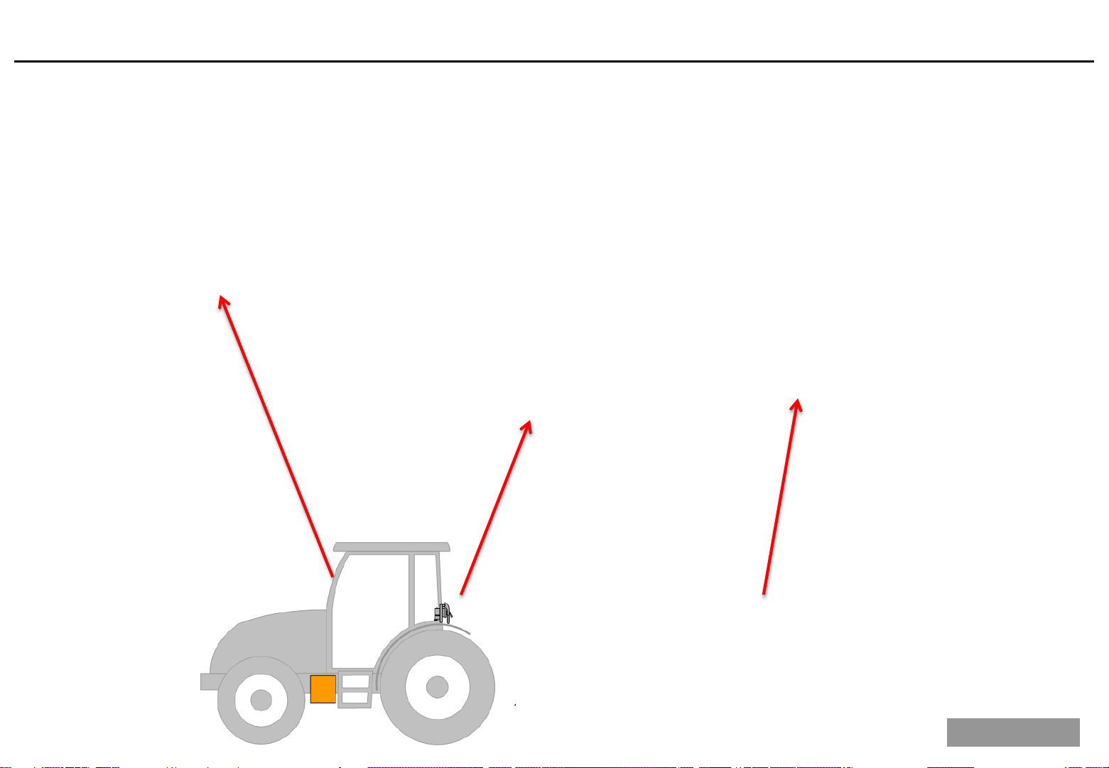
1.1 ISO spreader with a Non
-ISO tractor 4
1.2 ISO spreader with IM Tellus, Tellus GO or PRO
4
1.3 ISO spreader and ISO tractor
5
6
6
1.4.2 ISO Match Tellus and Tellus PRO
7
1.5 IM power (IsoMatch power)
8
9
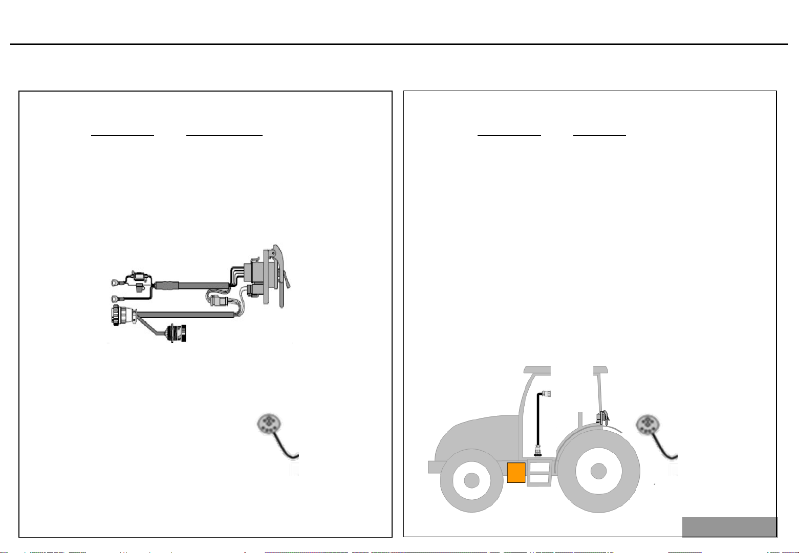
1.5.2 IM Tellus connection cable
11
12
-and power cables (Machine side) 13
14
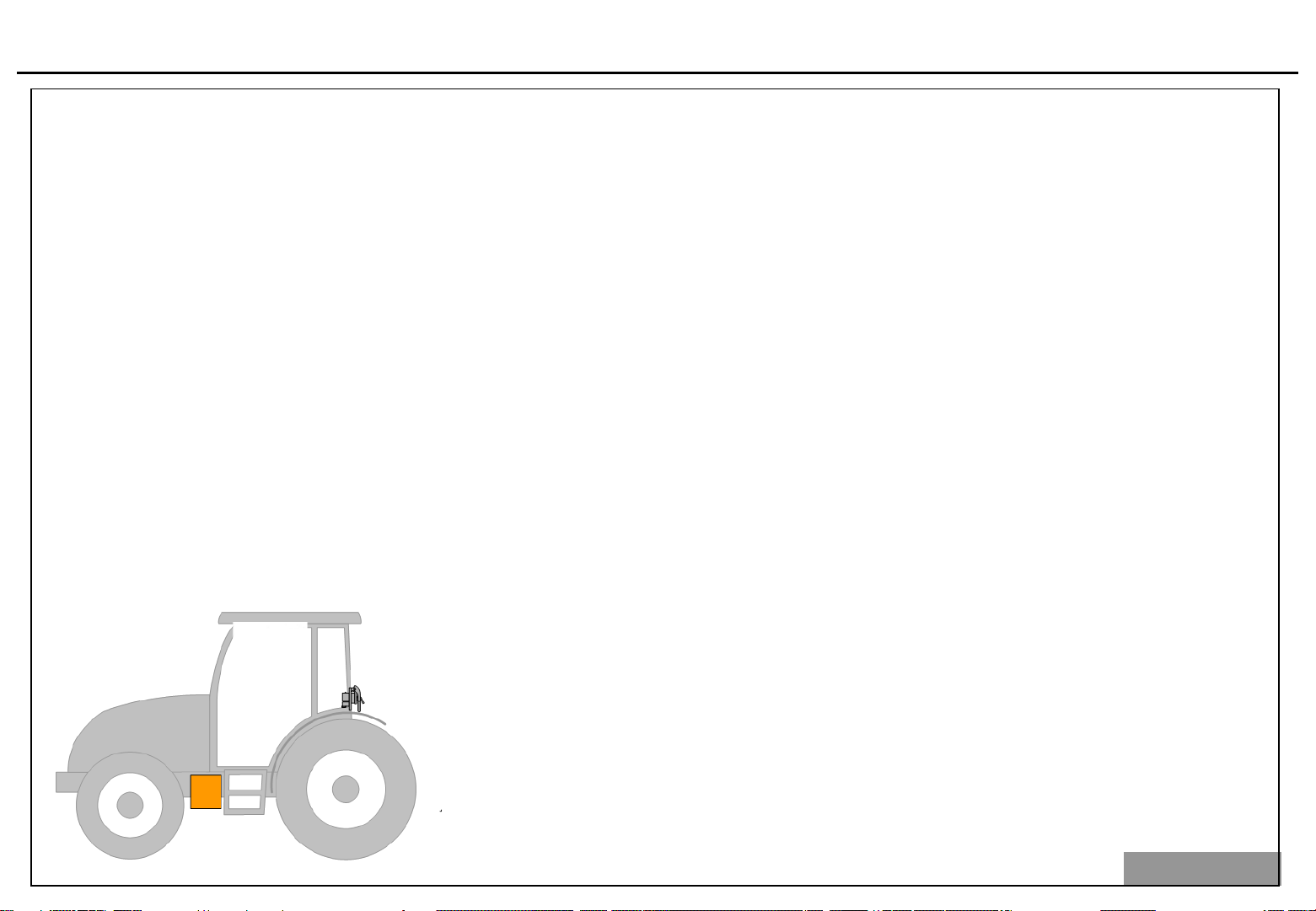
14
17
2.3 Inductie sensor (RPM)
19
21
2.4.1 Check the reference sensor
21
2.4.2 Testing the reference sensor
22
23
24
2.5.2 Test the load cells one by one
25
26
2.6.1 Testing the actuators
27
2.6.2 Measure the actuators
28
2.6.3 Repairing the actuators
29
31
3.1 Machine software EDW ISO II 1.17
32
33
3.3 Service screens: Settings behind PIN Code
38
3.4 Virtual Terminal setting and GEOCONTROL
41
43
46
4.1 Actuators calibration 46
4.2 Hopper calibration: (Pincode 5) 47
4.3 Hopper calibration: (Except CL EW and RO-M EW (Pincode 8) 52
4.4 Hopper calibration: RO-M EW CL EW (Pincode 8) 58
4.5 Speed sensor calibration 62
4.6 Diagnoctic stored calibrated value check 64
5. Border spreading and GEOCONTROL
65
Manual border spreading plate and GEOCONTROL 65
Hydraulic border spreading plate and GEOCONTROL 68
6. Implement setting GEOCONTROL
71
6.1 Calculating B distance
71
6.2 B setting under field conditions
73
76
76
7.2 Trouble should Flowchart weighing system
79
7.3 Trouble should Flowchart actuators
80
8. Electrical hopper cover
81
81
8.2 Connection on PCB and software
82
83
84
85
9.3 PCB connection and software
86
87
88