Kwik-file Security Shade User manual

Hardware List
:
- #10-16 x 1/2 Self-Tapping Screws Silver (10)
- #10-16 x 1/2 Self-Tapping Screws Black (2)
Kwik-File, LLC
Security Shade
Tools Required
:
- File
- Drill
- /16 Long Neck Hex Socket for Drill
- Phillips Screw Driver

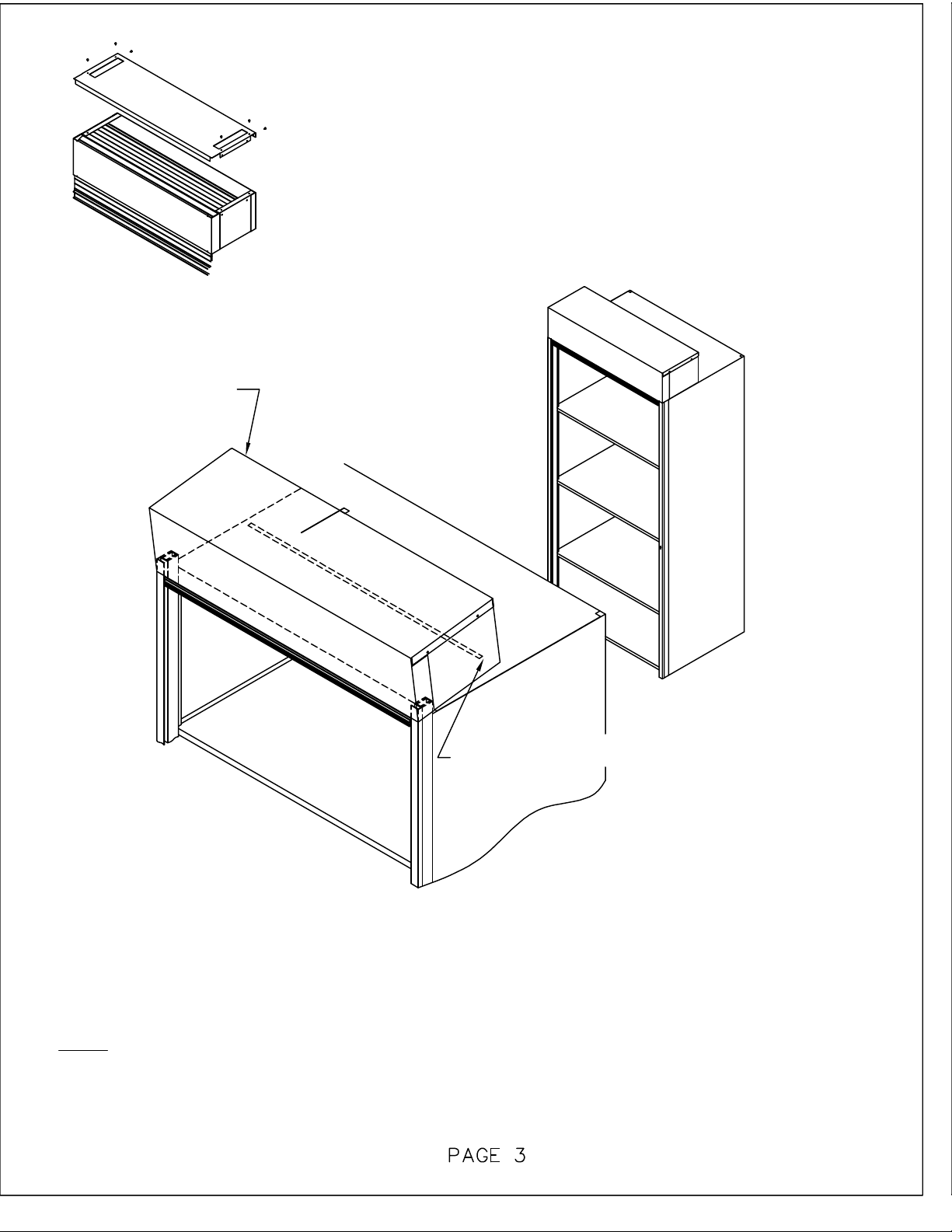
The Tambour Door is 36", 42" and 48" wide. All Kwik-file 4-Post units are 5/16" wider than
tambour door and requires the door tracks to be placed 5/32" from the outer edges. Mark this
distance at various places along each side upright of the Kwik-file 4-Post unit.
NOTE: If you are installing this door on a unit that measures 36", 42" or 48" wide, align the
Inner Track with the outer edge of that unit.
NOTE: The Track should extend above the unit about 1/4" to 2-3/8". If the track extends
beyond the 2-3/8" MAXIMUM , both the outer and inner track must be cut back.
Remove the protective covering from the tape on the back side of the Inner Track. Position the
bottom of the Inner Track flush with the bottom of the 4-Post upright. Align the Inner Track with
the marks you made or flush with the edge as noted in Step 1. Press track firmly in place.
Secure each Inner Track to the 4-Post Upright with (5) #10-16x1/2" silver Self-tapping Screws
equally spaced along the length of the track.
File or cut the top inner edge of BOTH Outer Tracks at 45°, which will allow the Tamb our Door
to travel more freely.
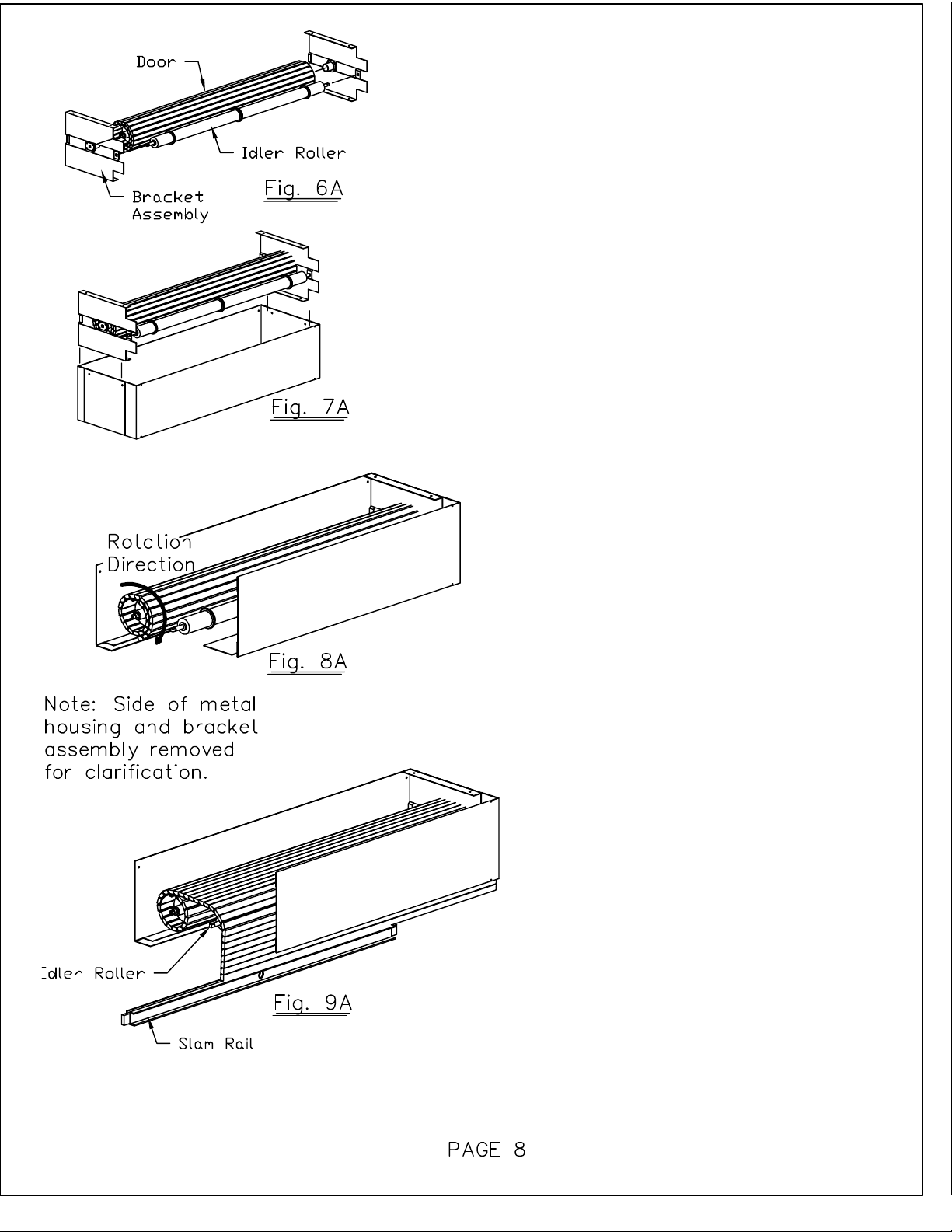
Snap the Outer Tracks into the mounted Inner Tracks.
Mount the Bottom Lock Rail with (2) #10-16x1/2" black Self-tapping screws to the bottom of the
tracks. If product is being mounted on Kwik Track, Mobile Lite or Mobile Aisle moveable
product, please see page 5.
6.
4.
5.
3.
2.
1.

7. Remove the Tambour Door Housing from its packaging. Housing
measures 8.25" vertically x 11.50" front to back x width of 4-post.
A. Remove (6) screws from housing top
B. Lift top housing off.
C. Remove internal packaging of housing. Verify door
rotates properly.
D. Replace top and (6) screws.
8. Lift Door housing to the top of the 4-Post Unit. Position the cutouts at the front of the housing
over the protruding track. Slide theTambour slats into the track.
9. Pull the Tambour Door down to verify that the door travels freely. Adjust housing position if
required.
Note: If vertical travel of door it too loose or too tight please see page 6 for trouble
shooting methods.
10. When adjustments have been made and the door moves freely. Lift the rear of the housing
and remove the protective cover from the double sided tape. Set the housing down and firmly
press in place.
Double-sided Tape
on Housing
Tambour Door
Housing

2.
3.
1. Use (3) 1/4"-14 x 3/4" TEK screws to secure locking rail to side of carriage. 3/4"
access holes are located on the front face of the locking rail to mount TEK screws to
carriage. Top of locking rail should be flush with top of bottom 4-post shelf.
Secure the locking rail to the track by using supplied holes in the locking rail with (4)
#10-16 x 1/4" black headed screws
Snap (3) 3/4" black plugs into holes on front side of locking rail for aesthetic
appearance. Return to step 7 to cotinue Security Shade installation.
Kwik Track, Mobile Lite or
Mobile Aisle Locking Rail
installation:
If you are using the Security Shade on a movable product, a
different locking rail is used. Discard original locking rail
provided with the Security Shade and install the mobile locking
rail using the instructions below.

Replacement Components
and Installation of Replacement Components
Replacement Part:
91209101R - Repl 36" door w/ spring hubs
91209301R - Repl 2" door w/ spring hubs
91209501R - Repl 8" door w/ spring hubs
Replacement Part:
91209102R - Repl Idler Roller 36" SS
91209302R - Repl Idler Roller 2" SS
91209502R - Repl Idler Roller 8" SS
Replacement Part:
91209103R - Repl Slam Rail 36" SS
91209303R - Repl Slam Rail 2" SS
91209503R - Repl Slam Rail 8" SS
Replacement Part:
85501501R - Repl bottom rail lock 36" SS
85501502R - Repl bottom rail lock 2" SS
85501503R - Repl bottom rail lock 8" SS
BOTTOM LOCK RAIL
SLAM RAIL W/ KEY LOCK
IDLER ROLLER
DOOR WITH SPRING HUBS
SPRING HUB
Replacement Part (Set of 2):
911002R - Repl spring hub 36" (Blue Dot on Hub)
911003R - Repl spring hub 2"/ 8" (Green Dot on Hub)
HARDWARE KIT
Replacement Part:
918799R - Repl hdwr kit
Sec. Shade
BRACKET ASSEMBLY
Replacement Part (Set of 2):
85503001R - Repl brckt assy, Sec. Shade

Tambour Door Trouble Shooting:
The tambour door is installed at the factory with one forward revolution to establish the correct
tension of the door. If operation of door is not satisfactory please follow the steps below. The
door can be rotated to either increase or decrease the tension.
1. Remove the top portion of the housing by removing the (6) screws. While holding the door in
position, remove the slam rail. Do not let go of door. Carefully allow door to retract back into
the housing.
2. To add tension to the door, rotate the door one revolution forward. To reduce tension to the
door, rotate the door one revolution backwards. Do not let go of door. Once the door has been
adjusted pull the leading edge of the door through the bottom slot and re-attach the slam rail.
3. Test unit for satisfactory tension. Repeat steps 2 if further adjustment is needed. Once door
movement is acceptable re-install top of housing with the (6) screws that were removed in step 1.

If after adjusting the Security Shade the door
still does not pull down properly, damage to the
Spring Hubs may have occured during
shipment. The following are steps to correct
this issue in the field.
1. Remove (6) screws from housing top and lift
top off. (Fig. 1A)
2. Observe how door is installed in housing, it
will have to be re-installed in the same manner.
While holding the door firmly, remove the slam
rail. Slowly allow the door to wind back into the
housing. (Fig. 1A)
3. Lift the Bracket Assemblies with the Door
and Idler Roller out of the metal housing. (Fig.
3A) Then remove the Bracket Assemblies.
(Fig. 3B)
4. Evaluate the Spring
Hubs to see if they have
been damaged. If they
have been damaged,
please follow the
remaining steps. If no
damage exists, proceed
to step 6. (Fig. 4A)
5. Unroll door on a soft surface (carpet or
cardboard) so damage to the door front does
not occur. Remove spring hubs and replace
them on the opposite end. The damaged
spring hub end should now be inside the
support rod. (Fig. 5A)
Side View

6. Tightly roll door back up, place a
piece of tape to hold door in tightly
rolled posistion. Re-assemble door and
idler roller onto bracket assemblies.
(Fig. 6A)
7. Place assembled door back into the
metal housing. (Fig. 7A)
8. Rotate door one complete
revolution. (Fig. 8A)
9. Hold door firmly and remove the
tape on the door. Pull tambour door
over idler roller and down through the
opening in the metal housing.
Continue to hold door firmly and
re-install the slam rail. (Fig. 9A)
10. Re-install metal housing top using
the (6) screws that were removed in
step 1. Set metal housing back on top
of unit and test door operation.
Table of contents
Other Kwik-file Indoor Furnishing manuals
Popular Indoor Furnishing manuals by other brands

SUNVILLA
SUNVILLA 2pk Assembly / care & use instructions

Home Decorators Collection
Home Decorators Collection Manhattan WSHCSSU Assembly instructions

Great Little Trading
Great Little Trading Star Bright L4944 quick start guide

Ameriwood HOME
Ameriwood HOME 6768335COM manual

Whalen
Whalen ODUS48CD-V manual

GLP
GLP GLS-62098-10KD Assembly instructions

JSI
JSI Moto Series installation instructions

Furniture of America
Furniture of America CM7865F Assembly instructions

Homelegance
Homelegance 1743-5 Assembly instruction

Bosch
Bosch 8981 021 140 Assembly guide

Viero Moveis
Viero Moveis Dallas Assembly instructions

Classic Exhibits
Classic Exhibits VISIONARY DESIGNS VK-1340 Setup instructions