Kwikee level best 2000 User manual

Table of Content
Page
Introduction 1
Safety Information 1
Operation 2
Control Panel 3
Manual Mode 3
Auto Mode 3
Stabalizing 4
Retracting Jacks 4
Setting Level Sensor 5
Care and Maintenance 5
Trouble Shooting Guide 6
Error Codes 6
Control Panel Jumper 7
Limited Warranty 8
Operation
Guide
Operation Guide
Products Company, Inc.
230 Davidson Avenue
Cottage Grove, Oregon 97424
(541) 942-3888
www.kwikee.com
©2003 Kwikee Products Co., Inc.
Kwikee Doc #1421901 Rev. Feb. 2004
Hydraulic Leveling Systems #2000, #2010, #3000, and #30130
The Level Best leveling and stabilizing system is an electronically controlled/hydraulical-
ly operated unit that consists of a 12 volt DC powered motor/pump/manifold assembly
with fluid reservoir, hydraulic hoses, four hydraulically operated jacks, a control unit with
switch panel, and optional level sensor unit and pressure sensor. It is designed to meet
the varying requirements of vehicles ranging from class “C” motorhomes to the large
class “A” motorhome.
If, after thoroughly reading this manual, you still have questions in regard to the opera-
tion and maintenance of the Level Best system, please contact the Kwikee Service
Department at 1-800-736-9961.
WARNINGS
Do not use the Level Best system as a lift for changing tires or working
under the vehicle.
Never check for hydraulic fluid leaks using your hands and/or any other body part. The
leaking fluid is under pressure and is capable of cutting and penetrating your skin
resulting in severe injury.
When extending the rear stabilizers, do not lift the wheels beyond ground contact. This
overrides the braking effect of both the transmission park and parking brake. Without
this braking, it is possible for the vehicle to roll unexpectedly forward (or backward) off
the jacks. This could cause severe injury or even death.
Holding a control switch in the "extend" or "retract" position for a time period longer
than necessary to fully extend or retract the hydraulic cylinders, can cause overheating
and damage to the pump motor as well as the electrical components.
Do not use the leveler as an emergency brake, They are not designed for any type of
vehicle braking purpose.
Do not use the levelers on icy or slick surfaces on which the foot pads may slip.
IN THE EVENT OF ACCIDENTAL EXTENSION
1. Bring the vehicle to a safe and complete stop as soon as possible.
2. Turn the leveling systems power switch on and press the all up switch.
3. Visually inspect the vehicle undercarriage for any problems.
Introduction

The control panel consists of switches and light
emitting diode indicators (Figure 1).
The switches include main power ON/OFF, all jacks
retract (ALL UP), a diamond shaped switch for bi-
lateral leveling
(BI-LEVEL), and four (UP/DN) switches for
independent extension and retraction of the jack
legs. The position of the UP/DN switches correspond
to the postion of the jack legs on your motor home,
with the front of the vehicle indicated by the top of
the panel.
The AUTO LEVEL switch only appears on motor
homes equipped with fully-automatic leveling.
Figure 1: Fully-automatic touchpad control panel shown.
The Level Best system performs the dual function of leveling the vehicle and, once a level
plane has been achieved, stabilizing the vehicle. When leveling the vehicle, it may not be
necessary to use all of the leveling jacks however, to stabilize the vehicle, all jacks should be
extended to contact the ground.
SITE SELECTION
1. When selecting a site for parking the vehicle, choose a spot that is as flat as possible -
this will minimize the extent of leveling.
2. Check that the area under the vehicle is free from any obstacles that might interfere with
the operation of the levelers. Check the ground surface to assure the leveler feet have a flat
solid surface for contact. When parking on grass, soft dirt and/or uneven terrain, it is
advisable to extend the surface area of the leveler feet by using pads. These pads can be
from 3/4" plywood, cut into 12" squares.
NOTE: In occasional adverse driving conditions, it is possible for mud, ice and other debris to
accumulate around the leveler units. This debris may interfere with the operation and should
be cleaned off prior to using the system.
CAUTION: Do not compensate for uneven terrain by using pads that are thicker than
3". Pads that are thicker than the leveler's vertical ground clearance can prevent
breaking contact with the ground when retracting. This can result in damage to both
the levelers and the vehicle.
NOTE: To prevent improper
operation of the leveling
system, which could result in
damage to the levelers and/or
the vehicle itself, read the
operating instructions
carefully before using the
leveling jacks.
Operation
Level Best Operation Guide Page 2

To stabilize the vehicle once it has been leveled, any unused leveler must be extended into
firm contact with the ground. Accomplish this by using the appropriate individual leg leveling
switch so as not to affect the level of the coach.
CAUTION: Overextending the levelers during stabilizing will cause the vehicle to
become unlevel and result in a loss of stability. If a leveler has been overextended,
press the ‘up’ portion of the respective switch until the vehicle lowers into the level
plane again. Do not attempt to use the other levelers to raise the vehicle to a higher
level plane.
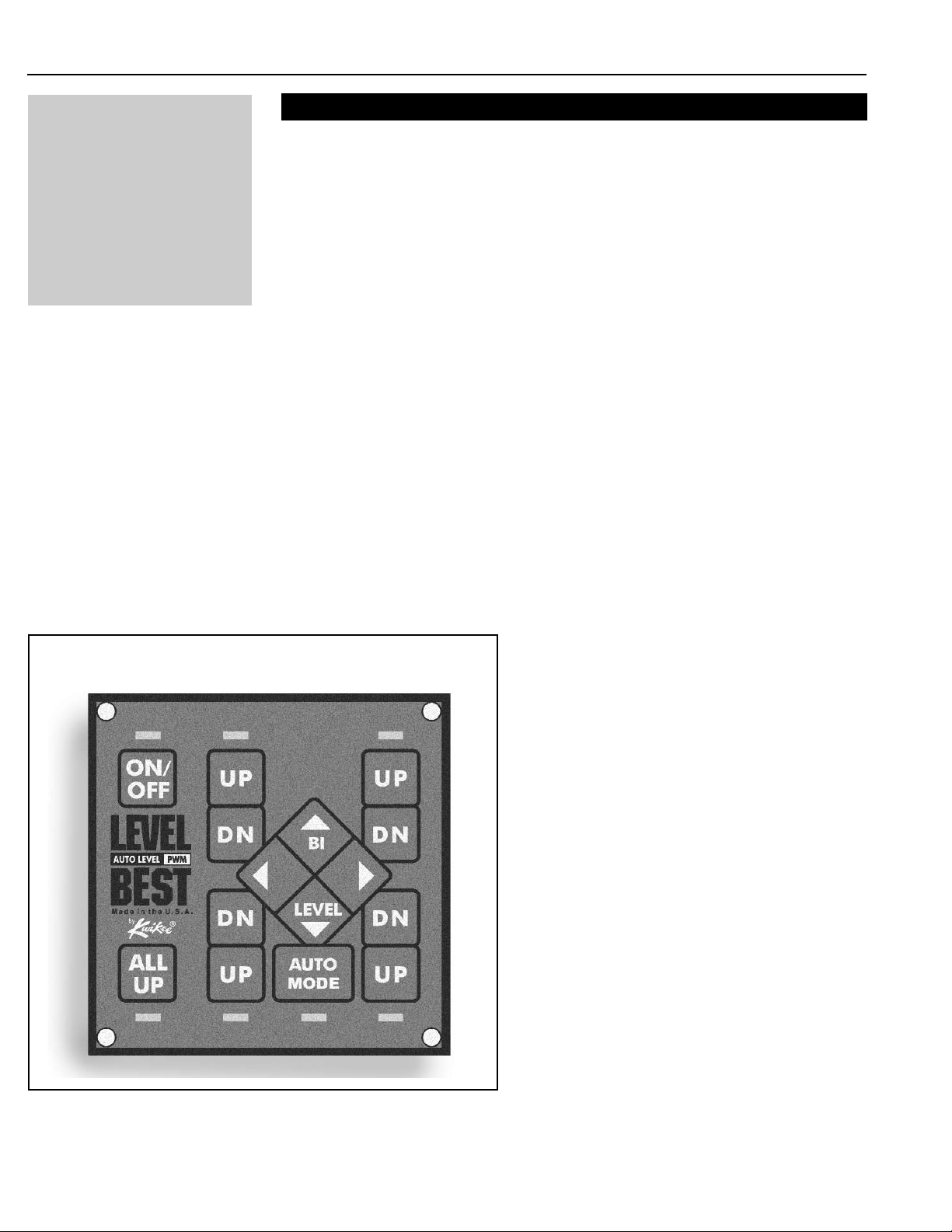
Control Panel Functions
Manual Leveling
The ON/OFF switch, located in the upper left hand corner, controls the supply of power for all
panel functions, activation of this switch is indicated by its green LED.
The ALL UP (leg retract) switch is located in the lower left hand corner of the control panel.
Activation of this switch causes all legs to retract to the travel position. When the retract
sequence is completed the ALL UP LED will turn green to indicate that it is now safe to move
the motor home.
The diamond shaped BI-LEVEL switch, located in the center of the panel, activates the
extension of the leveling jacks in pairs. Use of this switch greatly simplifies the leveling
process and significantly reduces the amount of stress created by the leveling process on the
motor home. Operation of this switch illuminates the yellow LED’s corresponding to the jacks
that are being activated. The LED will illuminate in manual version only.
The four UP/DOWN switches control the leveling jacks independently. Pushing these
switches operates the corresponding jack causing it to retract (UP) or extend (DN). Operation
of this switch lights the yellow LED corresponding with the jack activated. The LED will
illuminate in manual version only.
Level Best Operation Guide Page 3
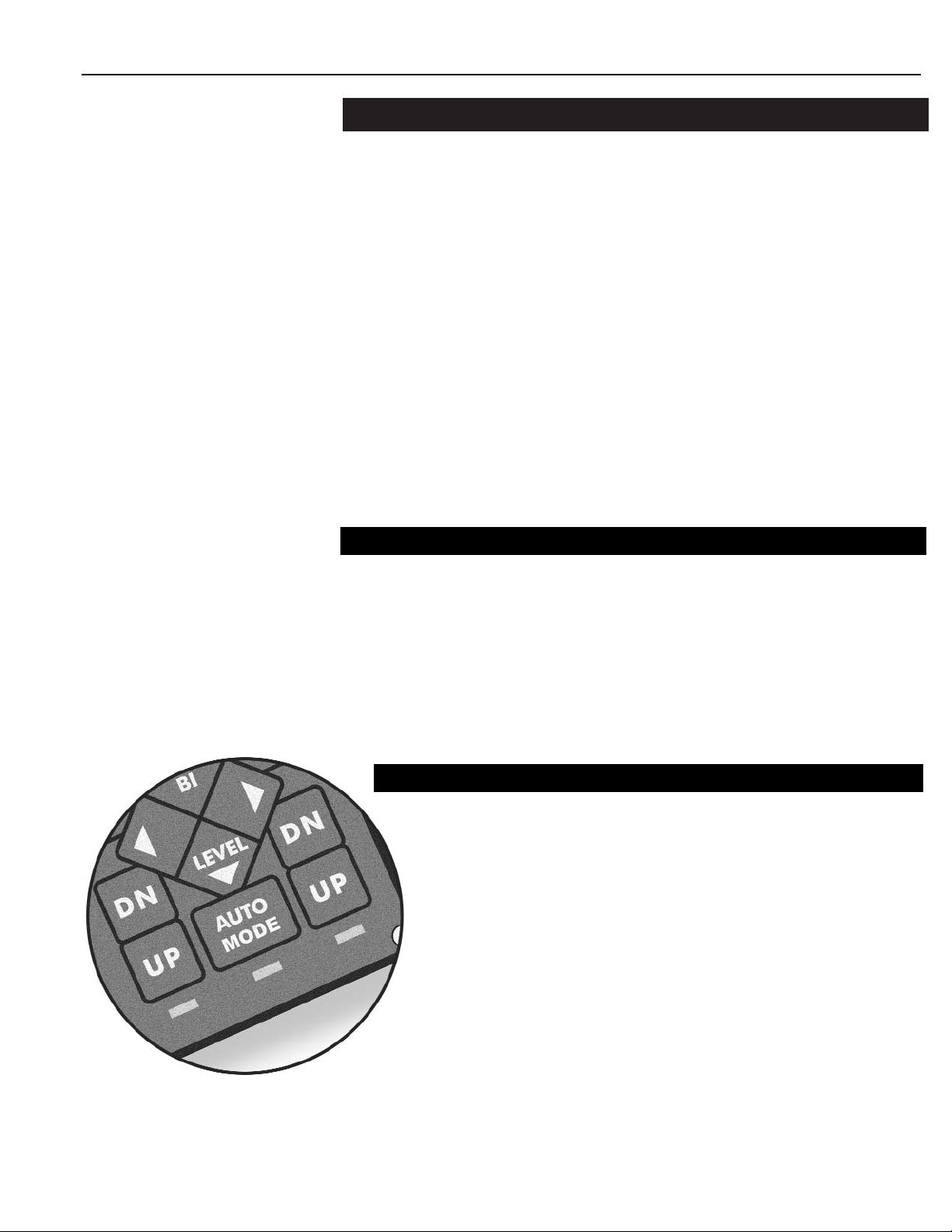
SEMI-AUTOMATIC FUNCTION When an AUTO MODE sensor is connected to
a manual control, the jack indicator lights act as an indicator of the level
condition of the coach. A light that is ‘on’ indicates the high corner of the
coach. Push the BI-LEVEL pair button corresponding to the end of the coach
you would like to raise. When the light comes ‘on’, stop the action of that
button. In this way the jack indicator lights act as a bubble-level, indicating
the level condition of the coach.
FULLY-AUTOMATIC FUNCTION Coaches equipped with AUTO MODE
can be operated the same as manual or semi-automatic versions. The fully-
automatic unit functions the same until the AUTO MODE switch is pressed.
Pushing the AUTO MODE switch causes the system to extend a pair of jack legs
to the ground. Next the other pair of legs is extended to the ground and the system
begins the auto level sequence. During the auto level sequence the system will run
one to three of the jacks depending on the level condition of the coach. On completion,
the system will check the level condition of the coach and either re-run the sequence
or display a green LED light under the AUTO MODE button to indicate that the
sequence is complete. Typical coach level capability is 0.3 degrees from side to
side and front to rear.
Automatic Leveling

Level Best Operation Guide Page 4
1. Start the chassis engine and turn the control panel power switch on. If any levelers are
extended, the control panel will emit a warning beep and the red "ALL UP" LED will light up
and flash.
2. To retract all levelers simultaneously, press the "ALL UP" switch. To retract each leveler
individually, press and hold the "UP" side of the respective leg switch. Using the "ALL UP"
switch is the recommended method of retracting the levelers to assure even retraction at all
four leveler locations and eliminate the possibility of twisting the chassis frame.
3. When all leveler legs retract to the travel position, the red "ALL UP" LED will turn green,
and the pump will shut off. You can now turn off the power switch and the vehicle is ready to
travel.
Retracting the Levelers
Observing the precautions set forth on the previous pages of this manual, you are now ready
to begin leveling your motor home. With the vehicle engine running, place the transmission in
park and set the parking brake. Securely block the wheels using wheel chocks.
Locate the "ON/OFF" button on the upper left of the control panel. Momentarily depress this
switch to activate the leveling system. The LED will light up and be a steady green indicating
that the system is ready. If the LED lights up and is flashing, it is an indication that the park-
ing brake is not completely engaged or the transmission is not in park.
Reference you’re leveling tool to determine which corner of the motor home is lowest. Using
one of the "BI-LEVEL" switches which represent the front and rear of the motor home. Use
the switch that corresponds to the low end of the motor home. Depress and hold the switch
to raise the sides of the motor home until level. Now find and depress the "BI-LEVEL" switch
which represents the low side of the motor home, and hold it until the front and rear of the
motor home are level.
Your motor home should now be in a level plane. If the coach has settled slighting, you
should fine-tune your position by using the individual leg leveling switches. Push the ‘’DN”
portion of the switch to raise the vehicle and the “UP” portion to lower the vehicle.
Stabilizing
NOTE: To prevent the
possibility of damaging the
levelers and/or vehicle, it is
good common sense to
confirm the retracted position
by visual inspection.

The Level Best hydraulic leveling system should be routinely checked as part of a
regular vehicle maintenance program. Kwikee recommends checking the system twice
a year: in the spring prior to the heavy travel season and in the winter, prior to storage.
The following checklist has been provided as a guideline for maintenance.
1. Be sure the leveling jacks are in the retracted position. Remove the breather cap
on the reservoir and check the fluid level in the reservoir. The fluid level should be
approximately 1" below the top of the reservoir. This standard provides an adequate
amount of fluid for the levelers to operate efficiently. If the fluid is below this level, add a
sufficient amount to bring the level up to the operating standard. When filling the
reservoir, use transmission fluid only. We recommend Dexron III. Do not mix fluids.
2. Check wire connections at motor and valve manifold; should be tight and secure.
3. Check the valve manifold for any evidence of hydraulic fluid leakage. Replace any
seals as needed.
4. Examine the hydraulic hoses for damage and/or leakage. Replace and resecure as
needed.
5. Check hydraulic cylinders and leg assemblies for damage and/or leakage. Replace
and/or repair as needed. Verify that all mounting bolts have been tightened to 80ft/lbs.
Care and Maintenance
Turn on the coach ignition and press the ON/OFF button on the control. The two top
indicator lights above the right and left front jack buttons will start flashing. The lights
indicate the warm up cycle of the level sensor. Aftr the warm up cycle the lights will stop
flashing. The cycle usually lasts between 2 and 10 minutes depending on outside
temperatures and whether it was previously run. The control will time-out every 60
seconds but the level sensor will continue to go through the warm up cycle anytime the
ignition of the coach is on.
When the warm up cycle is complete, turn off the control by pressing the ON/OFF
button. With the coach in a level attitude press and hold the ALL UP, BI-LEVEL FRONT
and BI-LEVEL REAR buttons simulaneously. You should hear an audible beep. Turn the
control back ‘on’ and all four indicator lights should now be lit indicating the level sensor
is showing the coach to be level. If all four LEDs are not illuminated, repeat last 2 steps.
Setting Level Sensor (if so equipped)
Level Best Operation Guide Page 5
NOTE: During periods of
vehicle inactivity and/or
storage, the leveling system
should be activated and
cycled through the
leveling/retracting procedures
on a monthly basis to keep
the levelers in good operating
condition.

Level Best Operation Guide Page 6
Troubleshooting
1. Panel does not function (buttons and lights do not work/system does not respond.)
• Ignition needs to be on with engine running
• Transmission needs to be in park and parking brake applied.
2. Red indicator light will not go out when legs are retracted.
• Reed switch(es) not grounded or reed switch is defective.
3. The action of one cylinder will not operate in one direction (i.e., it will go down,
but not up, or vice versa).
• Hydraulic hoses and/or wiring connections are crossed
• Valve not operating.
4. Jacks won‘t extend after they had been working previously.
• Directional valve is not shifting positions - possibly due to foreign object
obstructing the valve itself, or the solenoid is not working properly.
5. Pump continues to run after switch is released.
• Pump motor solenoid is stuck - tap solenoid to unstick it or replace the solenoid.
6. To retract jacks with a control failure, see Control Panel Jumper Instructions
on Page 7.
This list represents a cross section of some possible problems and the corresponding
solutions. After reviewing the manual, if you still have problems or questions, please
contact the Kwikee Service Department at 1-800-736-9961.
LED 7 green.
• Jacks retracted fully.
LED 7 red. Audible beep for approximately 8 seconds.
• Jacks deployed.
LED 6 green.
• Unit turned ‘on’.
LED 6 flashes.
• Park brake not set.
LEDs 1 and 2 flash.
• Level sensor in warm-up cycle.
LED 5 green and audible beep.
• Auto level sequence completed satisfactorily.
Standard Operating Codes
Alternating LEDs 1 and 2 ‘on’, then 3 and 4 ‘on’ etc.
• Coach tilted too far front to back to level.
Alternating LEDs 1 and 3 ‘on’, then 2 and 4 ‘on’ etc.
• Coach tilted too far side to side level.
LED 5 flashes red.
• Jacks are out of stroke.
LED 5 flashes green/red.
• Lost communication with Auto Level Sensor.
Auto Level Error Codes
LED Positions

Level Best Operation Guide Page 7
Control Panel Jumper Instructions
To be used in the event of a control failure.
1. Remove the control panel from the bezel and disconnect the wire harness.
(See Figure 2.)
2. Make sure the area around and below the motorhome is clear of all obstructions
and that no personnel are under the vehicle.
3. Plug the large connector of the jumper assembly into the wire harness (Figure 3.)
4. Plug the 4-way connector into the wire harness. CAUTION: Pump will start
immediately and the jacks will begin to retract. (See Figure 3.)
5. After jacks have been fully retracted, immediately disconnect the 4-way connector
on the jumper assembly from the wire harness to shut off the pump (Figure 3.)
Failure to immediately remove the 4-way connector can cause over-heating
of the pump motor and permanent damage to the system.
6. Remove the large connector of the jumper assembly from the wire harness.
7. Have jack system serviced at a qualified service center prior to using the jack
system.
Figure 2: Disconnect the wire
harness from the back of the
control panel.
Figure 3: Attach the Jumper Assembly to the Wire Harness.
NOTE: Immediately disconnect the 4-way connector after the jacks are fully
retracted. Failure to immediately remove the 4-way connector can cause
over-heating of the pump motor and permanent damage to the system.
4-WAY
CONNECTOR
JUMPER
ASSEMBLY
WIRE
HARNESS
CONTROL
PANEL
WIRE
HARNESS

Products Company, Inc.
230 Davidson Avenue
Cottage Grove, Oregon 97424
(541) 942-3888
www.kwikee.com ©2004 Kwikee Products Co., Inc. Kwikee Doc #1421901 Rev. Feb. 2004
Level Best Operation Guide Page 8
NOTE: Any parts returned for warranty service/repair with wires cut will result in
voiding of the warranty.
NOTE: It is important to read and understand this manual thoroughly before
initiating any installation of the jacks. Kwikee Products Company, Inc., assumes no
liability for damages or injury resulting from the improper installation or operation of
the Level Best® Hydraulic Leveling/Stabilizing System.
Kwikee Products Company, Inc. (“Kwikee”) warrants to the original purchaser that the Level Best®
hydraulic leveling/stabilizing system is free from defects in material and workmanship for a period of
5 years from the date of purchase. Kwikee’s obligation under this warranty is limited to the repair or
replacement of defective parts returned to Kwikee's' factory.
Kwikee will pay for the labor required to repair or replace its products on claims submitted within 2
years of the date of purchase. The warranty on repaired or replaced parts shall be limited to the
unexpired duration of the original warranty.
This warranty does not apply to products or parts that, in Kwikee’s opinion, have been subject to
abuse, accident, alteration, improper installation/repair, inadequate maintenance or deterioration due to
normal wear. This warranty does not apply to electrical wiring or hydraulic hoses. The purchaser shall
pay all shipping or other transportation charges for any warranty claim.
Kwikee makes no warranty (and disclaims any implied warranty) regarding the merchantability, fitness
for a particular purpose or the suitability of this product for use with other products. In no event shall
Kwikee be liable for incidental, consequential or property damage arising from the purchase and/or use
of this product or any claim hereunder. This warranty is in lieu of all other express and implied
warranties. Kwikee neither assumes nor authorizes any other person to assume any liability for
warranty claims not provided herein.
This warranty gives you specific legal rights including other rights that may vary from state to state.
Some states do not allow limitations on implied warranties and exclusion or limitation of incidental or
consequential damages, therefore the limitations and exclusions contained herein may not apply to you.
Any questions regarding warranty claims should be directed to your dealer or contact Kwikee Products
Company. Address correspondence to: Kwikee Customer Service Representative, 230 Davidson Ave.,
Cottage Grove, Oregon 97424; or contact us by telephone at 1-800-736-9961.
Limited Warranty
I M P O R T A N T
Please take a minute to fill in the
enclosed Level Best Warranty
Registration.
Send the completed registration
form to:
Kwikee Products
230 Davidson Ave.
Cottage Grove, OR 97424
Other manuals for level best 2000
1
This manual suits for next models
3
Table of contents
Other Kwikee Lifting System manuals
Popular Lifting System manuals by other brands

Challenger Lifts
Challenger Lifts LE12 Installation, operation & maintenance manual

BINAR
BINAR NEO 30 Original instructions

Altrex
Altrex 4100 Assembly and use manual

ThyssenKrupp
ThyssenKrupp orion installation manual

probst
probst AKZ-UNI-H operating instructions

Magliner
Magliner LiftPlus Lite owner's manual