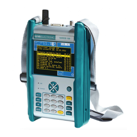
KWS Electronic VAROS 106 User manual

Contents 1
106 V3.2
Contents
Notes on Safety, Usage, Maintenance and Service.......................................................7Chapter 1
1.1 Safety notes ......................................................................................................................................... 7
1.2 Usage notes ......................................................................................................................................... 8
1.3 Maintenance......................................................................................................................................... 8
1.4 Cleaning ............................................................................................................................................... 8
1.5 Calibration ............................................................................................................................................ 8
1.6 Service ................................................................................................................................................. 8
Technical Data ...............................................................................................................9Chapter 2
Control and connection elements, pin configurations...................................................19Chapter 3
3.1 Front panel ......................................................................................................................................... 19
3.2 Rear panel.......................................................................................................................................... 20
3.3 Top section of instrument................................................................................................................... 21
USB-A socket..................................................................................................................................... 213.3.1
DVI output .......................................................................................................................................... 223.3.2
3.4 Bottom section of instrument.............................................................................................................. 22
12V power supply............................................................................................................................... 223.4.1
Startup..........................................................................................................................23Chapter 4
4.1 Mains operation.................................................................................................................................. 23
4.2 Battery operation................................................................................................................................ 23
Replacing the Li-Ion battery ............................................................................................................... 234.2.1
Battery management.......................................................................................................................... 244.2.2
4.3 Operation using an external power supply......................................................................................... 24
4.4 Ventilation control............................................................................................................................... 24
4.5 Switching on....................................................................................................................................... 24
4.6 Setting volume, brightness, contrast and color saturation ................................................................. 24
Menu structure .............................................................................................................25Chapter 5
5.1 Menu bar ............................................................................................................................................ 25
5.2 Drop-down menu................................................................................................................................ 26
SAT Measuring Range.................................................................................................27Chapter 6
6.1 Frequency input.................................................................................................................................. 27
IF input ............................................................................................................................................... 276.1.1
RF input.............................................................................................................................................. 276.1.2
6.1.2.1 Input of the oscillator frequencies....................................................................................................... 28
6.1.2.2 LO assignment ................................................................................................................................... 28
6.2 DVB-S/S2 operating mode................................................................................................................. 29
Selection of modulation...................................................................................................................... 296.2.1
Symbol rate input ............................................................................................................................... 296.2.2
Scan ................................................................................................................................................... 306.2.3
DVB-S/S2 parameters........................................................................................................................ 316.2.4
6.2.4.1 Parameters in the MPEG area ........................................................................................................... 31
Special receiver settings .................................................................................................................... 316.2.5
6.2.5.1 AFC (Automatic Frequency Control) .................................................................................................. 32
BER measurement (Bit Error Rate).................................................................................................... 326.2.6
MER measurement (Modulation Error Rate)...................................................................................... 336.2.7
Noise Margin (NM) ............................................................................................................................. 336.2.8
Constellation diagram......................................................................................................................... 336.2.9
PE measurement (Packet Error) ........................................................................................................ 336.2.10
Picture and sound check.................................................................................................................... 336.2.11
6.3 Level measurement............................................................................................................................ 33
Acoustic level trend ............................................................................................................................ 336.3.1

2 Contents
106 V3.2
6.4 LNB supply......................................................................................................................................... 34
14/18 V –22 kHz control.................................................................................................................... 346.4.1
Changing the fixed voltages............................................................................................................... 346.4.2
DiSEqC............................................................................................................................................... 366.4.3
6.4.3.1 DiSEqC V1.0 control .......................................................................................................................... 36
6.4.3.2 DiSEqC V1.1 control .......................................................................................................................... 36
6.4.3.3 DiSEqC V1.2 control .......................................................................................................................... 38
6.4.3.4 DiSEqC V2.0 control .......................................................................................................................... 40
UNICABLE (EN 50494)...................................................................................................................... 406.4.4
6.4.4.1 Activation and configuration ............................................................................................................... 41
6.4.4.2 Operation............................................................................................................................................ 43
6.4.4.3 Reading UB slot frequencies from CSS............................................................................................. 44
6.4.4.4 Programming antenna wall outlets..................................................................................................... 44
JESS (EN 50607)............................................................................................................................... 466.4.5
6.4.5.1 Activation and configuration ............................................................................................................... 46
6.4.5.2 Operation............................................................................................................................................ 47
6.4.5.3 Reading UB slot frequencies from CCS............................................................................................. 47
6.4.5.4 Programming antenna wall outlet....................................................................................................... 48
6.4.5.5 Show Continuous Wave (CW) tones.................................................................................................. 49
LNB current measurement ................................................................................................................. 506.4.6
DiSEqC Script .................................................................................................................................... 506.4.7
6.4.7.1 Do the DiSEqC Script......................................................................................................................... 50
6.4.7.2 Script structure ................................................................................................................................... 51
TV Measuring Range ...................................................................................................52Chapter 7
7.1 Switching between frequency and channel input ............................................................................... 52
Channel input ..................................................................................................................................... 527.1.1
Frequency input.................................................................................................................................. 527.1.2
7.2 Selecting of the operating mode......................................................................................................... 53
Analog (ATV) operating mode............................................................................................................ 537.2.1
7.2.1.1 Selecting the TV standard.................................................................................................................. 53
7.2.1.2 Sound carrier...................................................................................................................................... 53
7.2.1.3 Scan ................................................................................................................................................... 54
7.2.1.4 Picture and sound check.................................................................................................................... 54
7.2.1.5 S/N measurement .............................................................................................................................. 54
7.2.1.6 Noise Margin (NM) ............................................................................................................................. 55
DIGITAL (DVB-C, DOCSIS-Downstream, DVB-T/T2) operating mode ............................................. 557.2.2
7.2.2.1 DVB-C ................................................................................................................................................ 55
Symbol rate input ............................................................................................................................... 567.2.2.1.1
Scan ................................................................................................................................................... 567.2.2.1.2
DVB-C parameters............................................................................................................................. 577.2.2.1.3
BER measurement (Bit Error Rate).................................................................................................... 577.2.2.1.4
MER measurement (Modulation Error Rate)...................................................................................... 587.2.2.1.5
Noise Margin (NM) ............................................................................................................................. 587.2.2.1.6
PE measurement (Packet Error) ........................................................................................................ 587.2.2.1.7
Picture and sound check.................................................................................................................... 587.2.2.1.8
Constellation diagram......................................................................................................................... 58
7.2.2.1.9
7.2.2.2 DOCSIS (downstream)....................................................................................................................... 58
DOCSIS parameters .......................................................................................................................... 607.2.2.2.1
Scan ................................................................................................................................................... 617.2.2.2.2
BER measurement (Bit Error Rate).................................................................................................... 617.2.2.2.3
MER measurement (Modulation Error Rate)...................................................................................... 617.2.2.2.4
Noise Margin (NM) ............................................................................................................................. 617.2.2.2.5
PE measurement (Packet Error) ........................................................................................................ 617.2.2.2.6
Constellation diagram......................................................................................................................... 627.2.2.2.7
7.2.2.3 DVB-T................................................................................................................................................. 62

Contents 3
106 V3.2
Selection of the COFDM bandwidth (channel bandwidth) ................................................................. 637.2.2.3.1
Scan ................................................................................................................................................... 63
7.2.2.3.2
DVB-T parameters ............................................................................................................................. 647.2.2.3.3
Further DVB-T parameters................................................................................................................. 657.2.2.3.4
BER measurement (Bit Error Rate).................................................................................................... 657.2.2.3.5
MER measurement (Modulation Error Rate)...................................................................................... 657.2.2.3.6
Noise Margin (NM) ............................................................................................................................. 667.2.2.3.7
Impulse response............................................................................................................................... 667.2.2.3.8
PE measurement (Packet Error) ........................................................................................................ 687.2.2.3.9
Picture and sound check.................................................................................................................... 687.2.2.3.10
Remote supply ................................................................................................................................... 687.2.2.3.11
Constellation diagram......................................................................................................................... 687.2.2.3.12
7.2.2.4 DVB-T2............................................................................................................................................... 69
Selecting the COFDM bandwidth (channel bandwidth) ..................................................................... 697.2.2.4.1
Scan ................................................................................................................................................... 697.2.2.4.2
DVB-T2 parameters ........................................................................................................................... 707.2.2.4.3
Further DVB-T2 parameters............................................................................................................... 717.2.2.4.4
Selection of PLPs (Physical Layer Pipes) .......................................................................................... 717.2.2.4.5
BER measurement (Bit Error Rate).................................................................................................... 717.2.2.4.6
MER measurement (Modulation Error Rate)...................................................................................... 727.2.2.4.7
Noise Margin (NM) ............................................................................................................................. 727.2.2.4.8
Impulse response............................................................................................................................... 727.2.2.4.9
PE measurement (Packet Error) ........................................................................................................ 737.2.2.4.10
Picture and sound check.................................................................................................................... 737.2.2.4.11
Remote supply ................................................................................................................................... 737.2.2.4.12
Constellation diagram......................................................................................................................... 737.2.2.4.13
7.2.2.5 DTMB (Option) ................................................................................................................................... 74
Scan ................................................................................................................................................... 757.2.2.5.1
DTMB parameters.............................................................................................................................. 757.2.2.5.2
BER measurement (Bit Error Rate).................................................................................................... 767.2.2.5.3
MER measurement (Modulation Error Rate)...................................................................................... 767.2.2.5.4
Noise Margin (NM) ............................................................................................................................. 777.2.2.5.5
Impulse response............................................................................................................................... 777.2.2.5.6
PE measurement (Packet Error) ........................................................................................................ 787.2.2.5.7
Picture and sound check.................................................................................................................... 78
7.2.2.5.8
Constellation diagram......................................................................................................................... 787.2.2.5.9
Remote supply ................................................................................................................................... 787.2.2.5.10
7.3 Level measurement............................................................................................................................ 78
Acoustic level trend ............................................................................................................................ 787.3.1
Level measurement with DVB-C or DOCSIS ..................................................................................... 787.3.2
Level measurement with analog TV (ATV) ........................................................................................ 797.3.3
7.4 Diagrams............................................................................................................................................ 79
Operation............................................................................................................................................ 797.4.1
7.5 Blind Scan .......................................................................................................................................... 80
Starting a new scan............................................................................................................................ 807.5.1
Aborting a scan manually................................................................................................................... 807.5.2
Exporting the channel list ................................................................................................................... 817.5.3
FM (VHF) Measuring Range ........................................................................................82Chapter 8
8.1 Frequency input.................................................................................................................................. 82
8.2 Sound reproduction............................................................................................................................ 82
8.3 Stereo indicator .................................................................................................................................. 83
8.4 RDS (Radio Data System) ................................................................................................................. 83
8.5 Scan ................................................................................................................................................... 83
8.6 Level measurement............................................................................................................................ 83
Acoustic level trend ............................................................................................................................ 848.6.1
RC (Return Channel) Measuring Range ......................................................................85Chapter 9
9.1 Frequency input.................................................................................................................................. 85
9.2 Level measurement............................................................................................................................ 85

4 Contents
106 V3.2
Max hold function ............................................................................................................................... 869.2.1
Setting the channel bandwidth ........................................................................................................... 87
9.2.2
Acoustic level trend ............................................................................................................................ 879.2.3
DAB Measuring Range.................................................................................................88Chapter 10
10.1 Switching between frequency and channel input ............................................................................... 88
Frequency input.................................................................................................................................. 8810.1.1
Channel input ..................................................................................................................................... 8910.1.2
10.2 Scan ................................................................................................................................................... 89
10.3 Level measurement............................................................................................................................ 89
Acoustic level trend ............................................................................................................................ 8910.3.1
10.4 DAB parameters................................................................................................................................. 90
10.5 BER measurement (Bit Error Rate).................................................................................................... 90
10.6 MER measurement (Modulation Error Rate)...................................................................................... 91
10.7 FIC decoding...................................................................................................................................... 91
10.8 MSC decoding and audio playback.................................................................................................... 91
10.9 Remote supply ................................................................................................................................... 92
Setting the remote supply................................................................................................................... 9210.9.1
Measuring the remote supply current................................................................................................. 9210.9.2
Electromagnetic Interference Measurement.................................................................93Chapter 11
11.1 Calling-Up........................................................................................................................................... 93
11.2 Frequency input.................................................................................................................................. 93
11.3 Antenna selection............................................................................................................................... 94
User-defined EMI antenna ................................................................................................................. 9411.3.1
11.4 Entering the distance.......................................................................................................................... 94
11.5 Entering the limit................................................................................................................................. 94
11.6 Analysis of identifier ........................................................................................................................... 95
11.7 Measuring the interference field strength........................................................................................... 95
11.8 Setting the identifier............................................................................................................................ 95
11.9 Remote supply ................................................................................................................................... 96
Setting the remote supply voltage...................................................................................................... 9611.9.1
Changing the fixed remote supply voltages ....................................................................................... 96
11.9.2
MPEG Decoder............................................................................................................97Chapter 12
12.1 Program Service Information (PSI) .................................................................................................... 97
12.2 Network-Information-Table (NIT)........................................................................................................ 98
12.3 Logical Channel Numbering (LCN-List).............................................................................................. 99
12.4 Picture and sound check.................................................................................................................. 100
12.5 Display of MPEG video parameters ................................................................................................. 101
12.6 Video bit rate measurement ............................................................................................................. 101
12.7 Dynamic program switching ............................................................................................................. 101
Constellation diagram.................................................................................................102Chapter 13
13.1 Introduction....................................................................................................................................... 102
13.2 Operation.......................................................................................................................................... 103
13.3 Examples.......................................................................................................................................... 103
Memory management ................................................................................................106Chapter 14
14.1 Saving .............................................................................................................................................. 106
14.2 Recalling........................................................................................................................................... 106
14.3 Memory functions............................................................................................................................. 107
Erasing all memory........................................................................................................................... 10714.3.1
Erasing a memory location............................................................................................................... 10714.3.2
Sorting memory................................................................................................................................ 10714.3.3
Memory protection............................................................................................................................ 10714.3.4
Cancelling memory protection.......................................................................................................... 10814.3.5
Exporting the memory ...................................................................................................................... 10814.3.6
Importing the memory ...................................................................................................................... 10814.3.7
Spectrum analyzer .....................................................................................................109Chapter 15

Contents 5
106 V3.2
15.1 Accessing the analyzer .................................................................................................................... 109
15.2 Frequency segment (SPAN) ............................................................................................................ 110
15.3 Measuring bandwidth (RBW) ........................................................................................................... 110
15.4 Cursor............................................................................................................................................... 110
15.5 Input of the center frequency............................................................................................................ 110
15.6 Switching between frequency and channel mode............................................................................ 111
15.7 Level display..................................................................................................................................... 111
15.8 Progress bar..................................................................................................................................... 111
15.9 Level diagram in the broadband cable range................................................................................... 111
15.10 TILT measurement in the TV range ................................................................................................. 112
Digital level reduction ....................................................................................................................... 11315.10.1
Selecting a profile............................................................................................................................. 11315.10.2
Creating or changing a profile .......................................................................................................... 11415.10.3
Application........................................................................................................................................ 11515.10.4
15.11 Switching to measuring receiver mode ............................................................................................ 115
SAT range ........................................................................................................................................ 11515.11.1
15.11.1.1 Transponder SCAN.......................................................................................................................... 115
TV range in the channel input mode ................................................................................................ 11515.11.2
15.12 Max-Hold-Function........................................................................................................................... 116
15.13 Ingress measurement in the return path .......................................................................................... 117
SCAN Support for Finding Satellites ..........................................................................118Chapter 16
16.1 SAT SCAN ....................................................................................................................................... 118
16.2 SAT list............................................................................................................................................. 119
16.3 Transponder list................................................................................................................................ 120
16.4 Favorites list ..................................................................................................................................... 120
16.5 Importing a SAT list.......................................................................................................................... 121
Optical Receiver.........................................................................................................122Chapter 17
17.1 Introduction....................................................................................................................................... 122
17.2 Activating the optical input................................................................................................................ 123
17.3 Setting the wavelength..................................................................................................................... 123
17.4 Measuring the optical power ............................................................................................................ 124
17.5 Measuring the optical modulation index (OMI)................................................................................. 124
17.6 Cleaning the fiber optic plug connection .......................................................................................... 125
17.7 USB Microscope............................................................................................................................... 126
Operation.......................................................................................................................................... 12817.7.1
Logging............................................................................................................................................. 12917.7.2
Management of the instrument...................................................................................130Chapter 18
18.1 Keypad ............................................................................................................................................. 130
18.2 Language of the user guidance........................................................................................................ 130
18.3 Software ........................................................................................................................................... 130
Info ................................................................................................................................................... 13018.3.1
Update.............................................................................................................................................. 13018.3.2
18.4 Clock ................................................................................................................................................ 130
18.5 Serial number................................................................................................................................... 131
18.6 Factory settings................................................................................................................................ 131
18.7 User-defined TV channel table......................................................................................................... 132
D-Channels ...................................................................................................................................... 13218.7.1
18.8 Dynamic program switching ............................................................................................................. 132
18.9 Hardcopy.......................................................................................................................................... 133
18.10 Unlock software options ................................................................................................................... 134
Measurement Data Memory (DataLogger).................................................................135Chapter 19
19.1 Automatically storage of series of measurements............................................................................ 135
19.2 Transferring and evaluating a series of measurements on the PC .................................................. 136
19.3 Deleting a series of measurements from the instrument.................................................................. 136
Measurement Data Recording (DataGrabber) ...........................................................137Chapter 20

6 Contents
106 V3.2
20.1 Starting the recording....................................................................................................................... 138
20.2 Evaluating of the recording............................................................................................................... 140
20.3 Documenting a recording ................................................................................................................. 140
DVI Output .................................................................................................................141Chapter 21
USB-A Interface .........................................................................................................143Chapter 22
Common Interface......................................................................................................144Chapter 23
23.1 Inserting a CA module...................................................................................................................... 144
23.2 Operation.......................................................................................................................................... 144
23.3 Card menu........................................................................................................................................ 145
Wi-Fi™ .......................................................................................................................146Chapter 24
24.1 Introduction....................................................................................................................................... 146
24.2 Connecting antenna ......................................................................................................................... 146
24.3 Entering the WLAN Measurement Mode.......................................................................................... 146
24.4 MAC address of the wireless module............................................................................................... 146
24.5 Measurement Capabilities................................................................................................................ 147
Channel allocation............................................................................................................................ 14724.5.1
Overview of all access points in the area......................................................................................... 14724.5.2
Level measurement of a single access point ................................................................................... 14824.5.3
24.6 Tips for WiFi™ receive..................................................................................................................... 149
Figure Index ...............................................................................................................150Chapter 25

Chapter 1 - Notes on Safety, Usage, Maintenance and Service 7
106 V3.2
Notes on Safety, Usage, Maintenance and ServiceChapter 1
1.1 Safety notes
Please note the instructions and warnings contained in these operating instructions.
This instrument is built and tested according to EN61010-1 (protective measures for electronic
measuring instruments) .
Important! This instrument may only be powered with the power supply originally
delivered from the factory.
The instrument is in perfect working order upon leaving the factory. To maintain this condition and
to ensure safe operation, the user must check the instrument and the power cord regularly for
damage. A damaged power cord must be replaced immediately.
The instrument complies with the IP20 protection class according to EN60529.
Discharging via connectors may damage the instrument. Protect the instrument from electrostatic
discharge when handling and operating it.
Make sure that no external voltages greater than 70 Veff are applied to the measuring receiver’s RF
input since they may destroy the input circuits.
Do not cover the ventilation slots on the instrument. Doing so can lead to reduced air circulation in
the instrument, causing heat to accumulate. The electronic components can overheat as a result.
Important! Depending on the operating mode and the ambient temperature, overheating
can occur when the instrument is operated for extended periods in its
protective case and is on a flat surface. In this case, the instrument outputs a
warning message and then switches off.
Lithium-Ion accumulators must not be exposed to high temperatures or fire. If battery is replaced
incorrectly, there is a risk of explosion. Replace the batteries only with the original type (available
from a salesman in your area, wholesaler, or the manufacturer of the instrument). Do not short-
circuit the batteries.
Passage from the battery regulations (BattV)
This device contains a battery which incorporates hazardous substances. It
must not be disposed of I domestic waste. At the end of its working life it
should be disposed of only through the ESC customer service department
or at a designated collection point.

8 Chapter 1 - Notes on Safety, Usage, Maintenance and Service
106 V3.2
1.2 Usage notes
The guarantee for a new instrument ends 24 months after delivery.
The guarantee is invalidated if the instrument is opened!
Sharp tools (such as screwdrivers) can damage the plastic pane in front of the TFT display and
thus ruin the TFT.
The contrast of the TFT deteriorates at ambient temperatures below 5°C.
The TFT display does not reach maximum brightness until several seconds after the instrument is
cold-started.
The instrument reaches full measurement accuracy after about 5 minutes of operation.
Wireless DECT telephones and GSM mobile phones can cause malfunctions and incorrect
measurements if they are operated in the immediate vicinity of the measuring receiver.
1.3 Maintenance
The instrument is maintenance-free.
1.4 Cleaning
Clean the case and the TFT display with a soft, lint-free dust cloth. Never use solvents such as
diluents for cellulose lacquers, acetone or similar since they may damage plastic parts or the
coating on the front panel.
Remove dust from the ventilation slots regularly so that the air circulation provided by the
integrated ventilator is not obstructed.
1.5 Calibration
The instrument should be recalibrated at least every two years. The instrument is automatically
calibrated at the factory if returned for service.
1.6 Service
Service address: see back cover of operating manual.

Chapter 2 - Technical Data 9
106 V3.2
Technical DataChapter 2
FREQUENCY RANGE
SAT
910 –2,150 MHz
Resolution
1 MHz
IF- / Transponder frequency input
TV
45 –868 MHz
868 –1,214 MHz (Option)
Resolution
50 kHz
Frequency input / Channel input
FM (VHF)
87.4 –108.2 MHz
Resolution
50 kHz
RC (Return channel)
5 –65 MHz
Resolution
50 kHz
EMI
45 –868 (1,214) MHz
Resolution
50 kHz
DAB
170 –250 MHz
Resolution
50 kHz
Wi-Fi™
802.11 b/g/n
2,412 - 2,472 MHz
802.11 a
5,180 –5,700 MHz
OPERATION
Input
Illuminated silicone keypad
Monitor
5.7" TFT, VGA resolution (640 x 480)
User Prompting
via OSD (On Screen Display) german, english
Audio reproduction
Integrated stereo-loudspeaker
RF INPUT
IEC socket / 75 Ohm (DIN 45 325)
Return loss
> 12 dB (5 –1.214 MHz) all ranges except SAT
> 10 dB (910 –2.150 MHz) SAT
External voltage
max. 70 Veff (DC –50 Hz)
RF summation power
max. 500 mW (5 –2.150 MHz)
INPUT ATTENUATOR
0 –60 dB in 2 dB increments

10 Chapter 2 - Technical Data
106 V3.2
LEVEL RANGE
Measuring Ranges
SAT
30 –120 dBµV
TV
20 –120 dBµV
FM
20 –120 dBµV
RC
25 –120 dBµV
DAB
20 –120 dBµV
Resolution
0.1 dB
Measuring accuracy
± 1.5 dB (at 20°C) warm up time > 5 min.
± 2.0 dB (0°C –40°C) warm up time > 5 min.
Measuring bandwidth
SAT DVB-S/S2
8 MHz, 4 MHz or 1 MHz depending on symbol rate
TV analog
Video carrier 200 kHz
Audio carrier 200 kHz
DVB-C
4 MHz, 1 MHz, or 200 kHz depending on symbol
rate
FM
200 kHz
RC
1 MHz, 200 kHz or 90 kHz depending on bandwidth
symbol rate setting
EMI
200 kHz
DAB
1 MHz
Acoustic level trend
indicator
can be switched on/off
ANALYZER
Measuring bandwidth
SAT
8 MHz, 4 MHz, 1 MHz
(RBW(-3dB))
TV
4 MHz, 1 MHz, 200 kHz, 90 kHz
FM
200 kHz, 90 kHz
DAB
1 MHz, 200 kHz
RC
200 kHz, 90 kHz
Span (frequency segment)
SAT
Total range, 600 MHz, 150 MHz, 75 MHz
TV
Total range, 250 MHz, 100 MHz, 50 MHz, 25 MHz
FM
Total range, 10 MHz
DAB
Total range, 30 MHz
RC
Total range, 20 MHz
MAX hold function
Switch directly between analyzer mode and receiver mode

Chapter 2 - Technical Data 11
106 V3.2
DVB-S
QPSK demodulator
(per ETS 300421)
Symbol rates
2 –45 MSym/s
Frequency offset (df)
Resolution
0.1 MHz
Measuring accuracy
± 200kHz
Measuring parameters
CBER (before Viterbi)
1.00•10 -8
VBER (after Viterbi)
1.00•10 -8
MER
up to 20 dB
Noise Margin, NM
up to 10 dB
Resolution
0.1 dB
Measuring accuracy
± 1.5 dB
PE (Packet Errors)
up to 4•10 9
counts packet errors since the start of measurement
Automatic detection
DVB-S/DVB-S2
Scan function
DVB-S2
QPSK / 8PSK demodulator
16APSK, 32APSK
(per ETS 302307)
Symbol rates
2 –45 MSym/s
(for 32APSK up to 38 MSym/s)
Freqency offset (df)
Resolution
0.1 MHz
Measuring accuracy
± 100 kHz
Measuring parameters
(per ETR 290)
CBER (before LDPC)
1.00•10 -8
LBER (after LDPC)
1.00•10 -8
MER
up to 20 dB
Noise Margin, NM
up to 10 dB
Resolution
0.1 dB
Measuring accuracy
± 1.5 dB
PE (Packet Errors)
up to 4•10 9
counts packet errors since the start of measurement
Automatic detection
DVB-S/DVB-S2
Scan function

12 Chapter 2 - Technical Data
106 V3.2
TV ANALOG
Television standards
B/G, D/K, L, I, M/N
Color standards
PAL, NTSC, SECAM
Sound demodulator
Sound carrier 1 and 2
Decoding of MONO, STEREO and dual sound
broadcasts
Sound carrier measurement
Sound carrier 1 and 2 relative to the
video carrier, in dB
Resolution
0.1 dB
Measuring accuracy
± 1.5 dB
NICAM-DECODER
(per ETS 300163)
Sound carrier
5.85 MHz (B/G, D/K, L) and 6.552 MHz (I)
respectively
Decoding of MONO, STEREO and dual sound
broadcasts
S/N MEASURING
On analog video signals
evaluated measurement according to CCIR 569
Sources
TV analog
Measuring range
40 –55 dB
Noise Margin, NM
up to 10 dB
Resolution
0.1 dB
Measuring accuracy
± 1.5 dB
DVB-C AND EURO-DOCSIS
QAM demodulator
(per ETS 300163)
Symbol rates
1.0 –7.2 MSym/s
Modulation scheme
16, 32, 64,128 und 256 QAM
Measuring parameters
(per ETR 290)
BER
1.00 •10 -9
MER
up to 40 dB
Noise Margin, NM
up to 10 dB
Resolution
0.1 dB
Measuring accuracy
± 1.5 dB
PE (Packet Errors)
up to 4 • 10 9
counts packet errors since the start of measurement
Scan function

Chapter 2 - Technical Data 13
106 V3.2
J83B (US-DOCSIS)
QAM demodulator
(per ITU-T J.83B)
Symbol rates
5.057, 5.361 MSym/s
Modulation scheme
64, 256 QAM
De-Interleaver-Depths
I=8 / J=16, 16/8, 32/4, 64/2, 128/1
Measuring parameters
(per ETR 290)
VBER (after Viterbi)
1.00 • 10-6
MER
up to 40 dB
Noise Margin, NM
up to 10 dB
Resolution
0.1 dB
Measuring accuracy
± 1.5 dB
PE (Packet errors)
up to 4 • 109
counts packet errors since the start of measurement
Scan function
DVB-T
COFDM demodulator
(per ETS 300744)
Bandwidth
6, 7, 8 MHz
FFT
2k, 8k
Modulation scheme
QPSK, 16QAM, 64QAM
Guard intervals
1/4, 1/8, 1/16, 1/32
Measuring parameters
(per ETR 290)
CBER (before Viterbi)
1.00 • 10 -6
VBER (after Viterbi)
1.00 • 10 -8
MER
up to 35 dB
Noise Margin, NM
up to 10 dB
Resolution
0.1 dB
Measuring accuracy
± 1.5 dB
PE (Packet Errors)
up to 4 • 109
counts packet errors from start of measurement
Impulse response
Attenuation relative to the primary impulse 0-40 dB
Delay relative to the primary impulse in µs or km
Scan function

14 Chapter 2 - Technical Data
106 V3.2
DVB-T2
COFDM demodulator
(per ETS 302755)
Bandwidth
6, 7, 8 MHz
FFT
1k, 2k, 4k, 8k, 16k, 32k
Modulation scheme
QPSK, 16QAM, 64QAM, 256QAM
Guard intervals
1/4, 19/128, 1/8, 19/256, 1/16, 1/32, 1/128
Pilot pattern
PP1…PP8
Measuring parameters
(per ETR 290)
CBER (before LDPC)
1.00 •10 -6
VBER (after LDPC)
1.00 •10 -8
MER
up to 35 dB
Noise Margin, NM
up to 10 dB
Resolution
0.1 dB
Measuring Accuracy
± 1.5 dB
PE (Packet Errors)
up to 4 • 10 9
Counts packet errors from start of measurement
Impulse response
Attenuation relative to the primary impulse 0-40 dB
Delay relative to the primary impulse in µs or km
Scan function
DTMB
Demodulator
(per GB20600-2006)
Bandwidth
8MHz
Carrier mode
Single carrier modulation (C1)
Multiple carrier modulation OFDM (C3780)
Modulation scheme
4QAM, 4QAM_NR, 16QAM, 32QAM, 64QAM
Guard intervals
PN420v, PN595c, PN945v, PN420c, PN945c
FEC
0,4, 0,6, 0,8
Time interleave
M_240, M_720
Measuring parameters
(per ETR 290)
CBER (before DPC)
1.00 •10 -6
VBER (after DPC)
1.00 •10 -8
MER
up to 32 dB
Noise Margin, NM
up to 10 dB
Resolution
0.1 dB
Measuring accuracy
± 1.5 dB
PE (Packet Errors)
up to 4 • 10 9
Counts packet errors from start of measurement
Impulse response
Attenuation relative to the primary impulse 0-40 dB
Delay relative to the primary impulse in µs or km
Scan function

Chapter 2 - Technical Data 15
106 V3.2
CONSTELLATION DIAGRAM
I/Q analysis of digitally modulated signals
Sources
DVB-C, J83B, DVB-T, DVBT2, DTMB, DVBS,
DVBS2
3-dimensional display
In color
(Status frequency)
Zoom function
In all 4 quadrants (except DTMB)
Stop function
Freezes the diagram
FM (VHS)
MONO-/STEREO indicator
RDS (Radio Data System)
Station name, PI code
Scan function
DAB/DAB+
COFDM demodulator
(per ETSI EN 300401)
FFT
2k
Mode
1
Modulation scheme
DQPSK
Guard intervals
¼
Measuring parameters
CBER (before Viterbi)
1.00 • 10-6
MER
up to 25 dB
Resolution
0.1 dB
Measuring accuracy
± 1.5 dB
DAB+ frame decoding
(per ETS TS 102563)
Scan function
TII evaluation
MPEG 2/4/H/AVS DECODER
Display of MPEG video parameters
Video bit rate measurement in Mbit/s
Video decoding
MPEG-2 MP@HL
ISO/IEC 13818-2
MPEG-4 AVC
ISO/IEC 14496-10
ITU-T H.264
Option
MPEG-H L5.1
ISO/IEC 23008-2
ITU-T H.265
Option
AVS/AVS+
AVS1-P2 (Jizhun)
AVS1-P16 (Guangbo)
Audio decoding
MPEG-1 Layer I/II
ISO/IEC 13818-3
MPEG-2 AAC
ISO/IEC 13818-7
MPEG-4 AAC
ISO/IEC 14496-3
Dolby Digital AC-3,
Dolby Digital Plus
DAB audio decoding
MPEG-1 Layer II
ISO/IEC 11172-3 and 13818-3
DAB+ audio decoding
HE-AACv2
ISO/IEC 14496-3

16 Chapter 2 - Technical Data
106 V3.2
TRANSPORT STREAM
EVALUATION
NIT evaluation
Separate views for video, audio and data services
Dynamic PMT
LCD (Logical Channel Descriptor)
LCN (Logical Channel Numbering)
selected SI data
Chinese character set
Cyrillic character set
GB2312
CI (COMMON INTERFACE)
1 CI slot
Presentation of card menu
INTERFACE
DVI
As an alternative to the integrated TFT LCD display,
the video and audio signal can be transmitted
digitally to a TV device with a DVI/HDMI input.
Output impedance 100 Ohm
Difference output level typ. 1 Vpp
USB-A
USB-A socket for data logger and software update
USB 2.0
TUNING MEMORY
Memory locations
200
Memory protection function
ELECTRO MAGNETIC
INTERFERENCE
MEASUREMENT (EMI)
Evaluation of the 13-digit identifier for the KFG 242
frequency identification generator and measurement
of the interference field strength in connection with
the bearing equipment, consisting of the EMI 240/Y
Yagi antenna, EMI 240/V pre-amplifier and EMI
240/K adapter cable, or with the EMI 241 antenna.
Other antenna sets can be user defined.
Measuring range
3 –103 dBµV/m (EMI 241)
5 –105 dBµV/m (EMI 240)
Resolution
0.1 dB
Measuring accuracy
± 1.5 dB (at 20°C)
± 2.0 dB (0°C –40°C)

Chapter 2 - Technical Data 17
106 V3.2
OPTICAL RECEIVER
Connector
SC/APC (with protective cap)
Wavelength (Lambda)
1,260 –1,620 nm (no optical filter)
Max. optical input power
+8 dBm (continuous power)
Return loss
> 40 dB
Equivalent input noise (ON)
< 8 pA/√Hz
RF frequency range
5 –2,150 MHz
Input power, nominal
-7…+3 dBm
Measuring parameters
Optical power
-35 dBm…+9 dBm
Wavelength
(calibrated)
1,310 nm, 1,490 nm, 1,550 nm
Resolution
0.1 dB
Measuring accuracy
± 0.35 dB
Optical modulation index
(OMI)
individual OMI and total OMI
Resolution
0.1%
Measuring accuracy
± 10% (of displayed value)
REMOTE SUPPLY
Per RF input
Voltage
5 - 20 V in 1V steps
Power
up to 500 mA (short circuit-proof)
22kHz modulation
SAT only
0,8 Vpp
DiSEqC
SAT only
V1.0, V1.1, V1.2, V2.0, UNICABLE (EN 50494),
JESS (EN 50607)
Current measuring
range
0 –500 mA
resolution
1 mA
measuring accuracy
± 2% of final value
Short circuit message
Automatic switch-off
WI-FI™
Scan for access points in 2.4 and 5 GHz band with
visualization of reception level
Listing of access points according to channels with
reception level
Connection test with level measurement

18 Chapter 2 - Technical Data
106 V3.2
POWER SUPPLY
External 12V
11 –15 V DC max. 3.0A
or external primary power supply 12 V / 3 A
(included in delivery) via extra-low voltage jack
according to DIN 45323
Power consumption max. 36 W
Battery
Li-Ion battery package 7.2 V / 6.6 Ah
Operation time
approx. 3 hours (dependent upon the remote
supply, keypad illumination and operating mode)
automatic cutout as protection against exhaustive
discharge
Charging time
approx. 4 hours
Battery management
Battery can be charged using 12 V external supply
ENVIRONMENTAL
CONDITIONS
Operating temperature
0°C - +45°C
Storage temperature
-10°C - +55°C
Battery charging
temperature
+15°C - +35°C
ELECTROMAGNET COMPATIBILITY
See Declaration of Conformity
PROTECTION
See Declaration of Conformity
DIMENSIONS (W / H / D)
206mm x 297mm x 84mm
WEIGHT
Approx. 2.5kg with battery pack
QUANTITY OF DELIVERY
Included in the delivery
Transport case
IEC measuring cable 75 Ohm
Fiber cable SC/APC to SC/APC (option fiber)
Fiber cable SC/APC to FC/PC (option fiber)
Power supply and external power cable
USB stick
Wi-Fi™ Antenna (Option Wi-Fi™)
Manual

Chapter 3 - Control and connection elements, pin configurations 19
106 V3.2
Control and connection elements, pin configurationsChapter 3
3.1 Front panel
Figure 3-1 Front panel

20 Chapter 3 - Control and connection elements, pin configurations
106 V3.2
3.2 Rear panel
Figure 3-2 Rear panel
Table of contents
Other KWS Electronic Measuring Instrument manuals
Popular Measuring Instrument manuals by other brands

Motec
Motec PLM user manual

Tempo Communications
Tempo Communications OPM210 instruction manual

Epson
Epson Spectroproofer Setup and Maintenance

KPS
KPS KPS-AN10 instruction manual

Packet Power
Packet Power BGS72 Installation, operation and maintenance manual

Extech Instruments
Extech Instruments 380973 instruction manual