manuals.online logo
Brands
  1. Home
  2. •
  3. Brands
  4. •
  5. Kyocera
  6. •
  7. All In One Printer
  8. •
  9. Kyocera KM-1620 Administrator guide

Kyocera KM-1620 Administrator guide

Downloaded from www.coronatechnical.com manuals search
engine
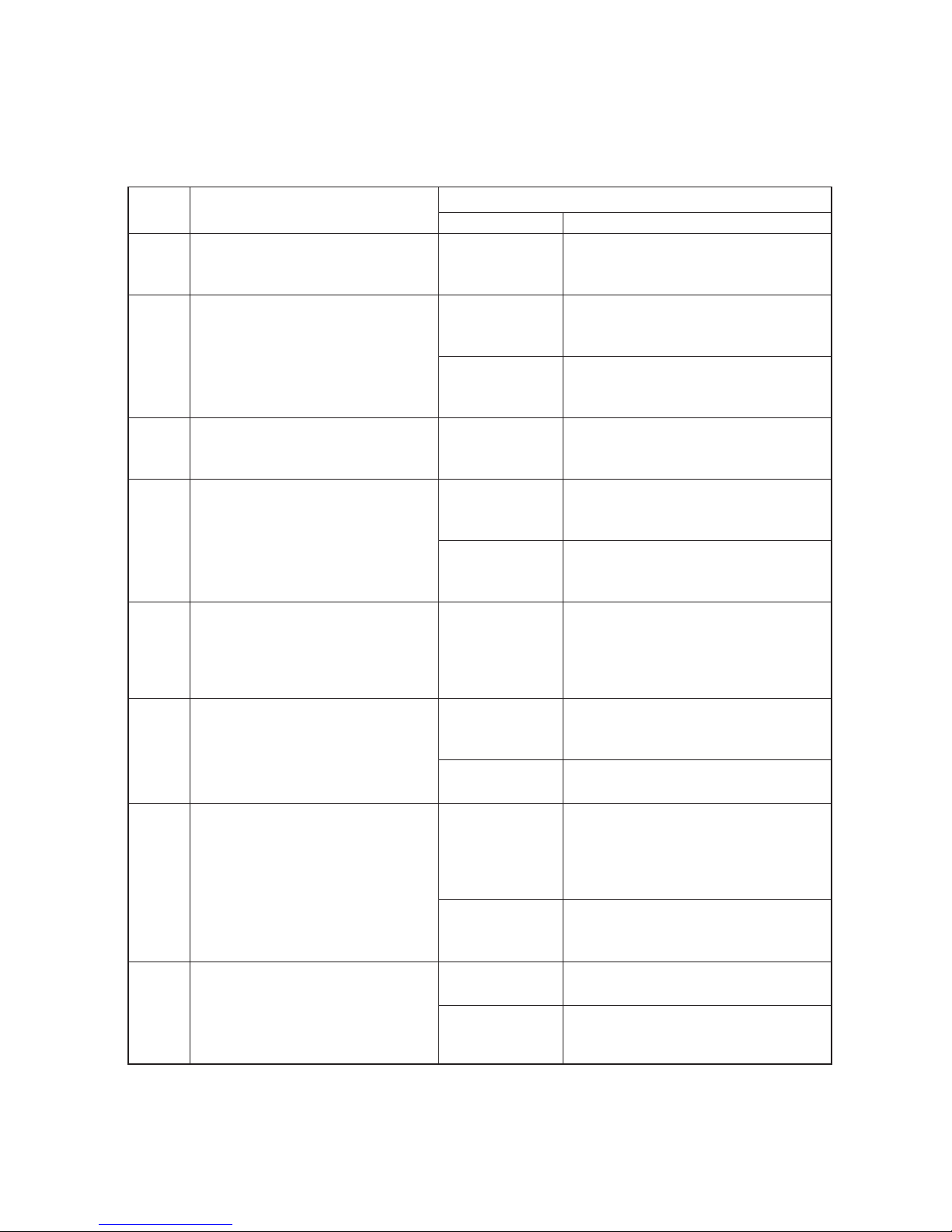
Kyocera KM-1620/ KM-2020 Error Code List
Self-diagnosis
(1)
Self diagnostic codes
Code
Contents
Remarks
Causes
Check procedures/corrective measures
C0100
(A0100*)
Backup memory read/write problem
(main PCB)
•
Read and write data does not match.
Defective backup
RAM or main
PCB.
Replace the main PCB and check for cor-
rect operation.
C0110
(A0110*)
Backup memory data problem (main
PCB)
•
Data in the specified area of the
backup memory does not match the
specified values.
Problem with the
backup memory
data.
Turn safety switch off and back on and run
maintenance item U020 to set the contents
of the backup memory data again.
Defective backup
RAM.
If the C011 is displayed after re-setting the
backup memory contents, replace the
backup RAM or main PCB.
C0150
(A0150*)
Backup memory read/write problem
(engine PCB)
•
Read and write data does not match.
Defective backup
RAM or engine
PCB.
Replace the engine PCB and check for
correct operation.
C016
(A016*)
Backup memory data problem (en-
gine PCB)
•
Data in the specified area of the
backup memory does not match the
specified values.
Problem with the
backup memory
data.
Turn safety switch off and back on and run
maintenance item U020 to set the contents
of the backup memory data again.
Defective backup
RAM.
If the C016 is displayed after re-setting the
backup memory contents, replace the
backup RAM or engine PCB.
C0170
Accounting count problem
•
When the power is turned on, the to-
tal count and the scan count are ab-
normal both on the main PCB and the
engine PCB.
Defective main
PCB or engine
PCB.
Replace the main PCB or engine PCB and
check for correct operation.
C0180
Machine number mismatch
•
When the power is turned on, thema-
chine number does not match be-
tween the main PCB and the engine
PCB.
Correct EEPROM
is not installed.
Install the correct EEPROM. If it does not
solve the problem, contact the Service Ad-
ministrative Division.
Data damage of
EEPROM.
Contact the Service Administrative Divi-
sion.
C0210
(A0210*)
Communication problem between
the main PCB and engine board PCB
•
When the power is turned on, thema-
chine does not detect the low level of
SBSY and the high level of SDIR for
three seconds.
Poor contact in
the connector ter-
minals.
Check the connection of connectors YC6
on the main PCB and YC1 on the engine
PCB, and the continuity across the connec-
tor terminals. Repair or replace if neces-
sary.
Defective main
PCB or engine
PCB.
Replace the main PCB or engine PCB and
check for correct operation.
C0410
(A0410*)
Optional DP communication problem
•
Communication fails five times suc-
cessively.
DP installed incor-
rectly.
Check the installation state of the DP and
adjust it if it is not properly installed.
Defective main
PCB or DP driver
PCB.
Replace the main PCB or DP driver PCB
and check for correct operation.
“A” is displayed on the operation panel.
Downloaded from www.coronatechnical.com manuals search
engine
Code
Contents
Remarks
Causes
Check procedures/corrective measures
C0420
(A0420*)
Optional first paper feedercommuni-
cation problem
•
Communication fails five times suc-
cessively.
Paper feeder in-
stalled incorrectly.
Check the installation state of the paper
feeder and adjust it if it is not properly in-
stalled.
Defective main
PCB or drawer
main PCB.
Replace the main PCB or drawer main
PCB and check for correct operation.
C0500
(A0500*)
Optional second paper feeder com-
munication problem
•
Communication fails five times suc-
cessively.
Paper feeder in-
stalled incorrectly.
Check the installation state of the paper
feeder and adjust it if it is not properly in-
stalled.
Defective main
PCB or drawer
main PCB.
Replace the main PCB or drawer main
PCB and check for correct operation.
C0510
(A0510*)
Optional third paper feeder commu-
nication problem
•
Communication fails five times suc-
cessively.
Paper feeder in-
stalled incorrectly.
Check the installation state of the paper
feeder and adjust it if it is not properly in-
stalled.
Defective main
PCB or drawer
main PCB.
Replace the main PCB or drawer main
PCB and check for correct operation.
C0610
(A0610*)
Bitmap (DIMM) problem
•
There is a problem with the dataor
address bus of the bitmapDRAM.
Defective main
PCB.
Replace the main PCB and check for cor-
rect operation.
DIMM installed
incorrectly.
Check if the DIMM is inserted into the
socket on the main PCB correctly.
Defective DIMM.
Replace the DIMM and check for correct
operation.
C0620
(A0620*)
Memory input interface problem
•
Reading-in of an image does not
complete within 10 s of the start of
image transmission.
Defective main
PCB.
Replace the main PCB and check for cor-
rect operation.
C0630
(A0630*)
DMA problem
•
DMA transmission of compressed,
decompressed, rotated, relocated or
blanked-out image data does not
complete within the specified period
of time.
Defective main
PCB.
Replace the main PCB and check for cor-
rect operation.
C0800
(A0800*)
Image processing problem
•
JAM05 is detected twice.
Defective engine
PCB.
Replace the engine PCB and check for
correct operation.
C2000
Drive motor problem
•
LOCK ALM signal remains high for 1
s, 1 s after the drive motor hasturned
on.
Poor contact in
the main motor
connector termi-
nals.
Reinsert the connector. Also check for con-
tinuity within the connector cable. If none,
remedy or replace the cable.
Defective drive
motor rotation
control circuit.
Replace the drive motor.
Defective drive
transmission sys-
tem.
Check if the rollers and gears rotate
smoothly. If not, grease the bushings and
gears. Check for broken gears and replace
if any.
“A” is displayed on the operation panel.
Downloaded from www.coronatechnical.com manuals search
engine
Code
Contents
Remarks
Causes
Check procedures/corrective measures
C3100
Scanner carriage problem
•
The home position is not correct
when the power is turned on or copy-
ing the document placed on the con-
tact glass.
Poor contact of
the connector ter-
minals.
Reinsert the connector. Also check for con-
tinuity within the connector cable. If none,
remedy or replace the cable.
Defective scanner
home position
switch.
Replace the scanner home position switch.
Defective engine
PCB.
Replace the engine PCB and check for
correct operation.
Defective scanner
motor.
Replace the scanner motor.
C3200
(A3200*)
Exposure lamp problem
•
In indicator check before starting
copying, the average value in scan-
ning of the shading plate with the
CCD is 128 or more.
Poor contact of
the connector ter-
minals.
Reinsert the connector. Also check for con-
tinuity within the connector cable. If none,
remedy or replace the cable.
Defective expo-
sure lamp or in-
verter board.
Replace the exposure lamp or inverter
board.
Defective engine
PCB.
Replace the engine PCB and check for
correct operation.
Incorrect shading
position.
Adjust the position of the contact glass
(shading plate). If the problem still occurs,
replace the scanner home position switch.
C3300
(A3300*)
Optical system (AGC) problem
•
After AGC, correct input is not ob-
tained at CCD.
Insufficient expo-
sure lamp lumi-
nosity.
Replace the exposure lamp or inverter
board.
Defective engine
PCB.
Replace the engine PCB and check for
correct operation.
Incorrect shading
position.
Adjust the position of the contact glass
(shading plate). If the problem still occurs,
replace the scanner home position switch.
C4000
Polygon motor synchronization
problem
•
The polygon motor does not reach
the stable speed within 15 s of the
START signal turning on.
Poor contact in
the polygon motor
connector termi-
nals.
Reinsert the connector. Also check for con-
tinuity within the connector cable. If none,
remedy or replace the cable.
Defective polygon
motor.
Replace the LSU.
Defective engine
PCB.
Replace the engine PCB and check for
correct operation.
C4010
Polygon motor steady-state problem
•
The polygon motor rotation is not
stable for 5 s after the polygon motor
rotation has been stabilized.
Poor contact in
the polygon motor
connector termi-
nals.
Reinsert the connector. Also check for con-
tinuity within the connector cable. If none,
remedy or replace the cable.
Defective polygon
motor.
Replace the LSU.
Defective engine
PCB.
Replace the engine PCB and check for
correct operation.
“A” is displayed on the operation panel.
Downloaded from www.coronatechnical.com manuals search
engine
Code
Contents
Remarks
Causes
Check procedures/corrective measures
C4200
(A4200*)
BD steady-state problem
•
The MIC detects a BD error for 600
ms after the polygon motor rotation
has been stabilized.
Defective laser
diode.
Replace the LSU.
Defective polygon
motor.
Replace the LSU.
Defective main
PCB.
Replace the main PCB and check for cor-
rect operation.
Defective engine
PCB.
Replace the engine PCB and check for
correct operation.
C6000
Broken fixing heater wire
•
In fixing warm-up, the time to reach
50°C/122 °F exceeds 13.5 s, the time
to reach 100°C/212 °F exceeds 10 s,
the time to reach the primary stabili-
zation exceeds 10 s or the time to
reach the secondary stabilization ex-
ceeds 24 s.
Poor contact in
the thermistor
connector termi-
nals.
Reinsert the connector. Also check for con-
tinuity within the connector cable. If none,
remedy or replace the cable.
Fixing thermistor
installed incor-
rectly.
Check and reinstall if necessary.
Fixing thermostat
triggered.
Check for continuity. If none, replace the
fixing thermostat.
Fixing heater M or
S installed incor-
rectly.
Check and reinstall if necessary.
Broken fixing
heater M or S
wire.
Check for continuity. If none, replace the
heater lamp.
C6020
Abnormally high fixing unit ther-
mistor temperature
•
The fixing temperatureexceeds
230°C/446 °F for 40 ms.
Shorted ther-
mistor.
Measure the resistance. If it is 0 , replace
the thermistor.
Broken heater
control circuit on
the power supply
PCB.
Replace the power supply PCB and check
for correct operation.
C6050
Abnormally low fixing unit ther-
mistor temperature
•
The fixing temperature remains below
90°C/194°F for 1 s.
Poor contact in
the thermistor
connector termi-
nals.
Reinsert the connector. Also check for con-
tinuity within the connector cable. If none,
remedy or replace the cable.
Broken fixing ther-
mistor wire.
Measure the resistance. If it is , replace
the fixing thermistor.
Fixing thermistor
installed incor-
rectly.
Check and reinstall if necessary.
Fixing thermostat
triggered.
Check for continuity. If none, replace the
fixing thermostat.
Fixing heater M or
S installed incor-
rectly.
Check and reinstall if necessary.
Broken fixing
heater M or S
wire.
Check for continuity. If none, replace the
fixing heater M or S.
“A” is displayed on the operation panel.
Code
Contents
Remarks
Causes
Check procedures/corrective measures
C6400
Zero-crossing signal problem
•
The engine PCB does not detect the
zero-crossing signal for the time
specified below.
At power-on: 3 s
Others: 5 s
Poor contact in
the connector ter-
minals.
Reinsert the connector. Also check for con-
tinuity within the connector cable. If none,
remedy or replace the cable.
Defective power
supply PCB.
Check if the zero-crossing signal is output
from CN2-5 on the power supply PCB. If
not, replace the power supply PCB.
Defective engine
PCB.
Replace the engine PCB if C640 is de-
tected while CN2-5 on the power supply
PCB outputs the zero-crossing signal.
C7800
Broken external temperature ther-
mistor
•
The input voltage is 0.5 V or less.
Poor contact in
the humidity sen-
sor connector ter-
minals.
Reinsert the connector. Also check for con-
tinuity within the connector cable. If none,
remedy or replace the cable.
Defective humidity
sensor.
Replace the drawer PCB and check for
correct operation.
C7810
Short-circuited external temperature
thermistor
•
The input voltage is 4.5 V or more.
Poor contact in
the humidity sen-
sor connector ter-
minals.
Reinsert the connector. Also check for con-
tinuity within the connector cable. If none,
remedy or replace the cable.
Defective humidity
sensor.
Replace the drawer PCB and check for
correct operation.

Other manuals for KM-1620

3

This manual suits for next models

1

Other Kyocera All In One Printer manuals

Kyocera FS-C1020MFP+ User manual

Kyocera

Kyocera FS-C1020MFP+ User manual

Kyocera TASKalfa 650c User manual

Kyocera

Kyocera TASKalfa 650c User manual

Kyocera ECOSYS FS-C8520MFP User manual

Kyocera

Kyocera ECOSYS FS-C8520MFP User manual

Kyocera ECOSYS M6530cdn User manual

Kyocera

Kyocera ECOSYS M6530cdn User manual

Kyocera ECOSYS M6026cidn User manual

Kyocera

Kyocera ECOSYS M6026cidn User manual

Kyocera ECOSYS MA6000ifx User manual

Kyocera

Kyocera ECOSYS MA6000ifx User manual

Kyocera KM-2530 User manual

Kyocera

Kyocera KM-2530 User manual

Kyocera ECOSYS FS-C2626MFP User manual

Kyocera

Kyocera ECOSYS FS-C2626MFP User manual

Kyocera TASKalfa 2550ci User manual

Kyocera

Kyocera TASKalfa 2550ci User manual

Kyocera KM-2560 User manual

Kyocera

Kyocera KM-2560 User manual

Kyocera ECOSYS M6535cidn User manual

Kyocera

Kyocera ECOSYS M6535cidn User manual

Kyocera ECOSYS M6030cdn User manual

Kyocera

Kyocera ECOSYS M6030cdn User manual

Kyocera KM-2030 manual 

Kyocera

Kyocera KM-2030 manual 

Kyocera SP C231SF User manual

Kyocera

Kyocera SP C231SF User manual

Kyocera ECOSYS FS-3540MFP User manual

Kyocera

Kyocera ECOSYS FS-3540MFP User manual

Kyocera FS FS-1020D User manual

Kyocera

Kyocera FS FS-1020D User manual

Kyocera KM-C2525E User manual

Kyocera

Kyocera KM-C2525E User manual

Kyocera KM-5050 User manual

Kyocera

Kyocera KM-5050 User manual

Kyocera TASKalfa 650c User manual

Kyocera

Kyocera TASKalfa 650c User manual

Kyocera C2525E User manual

Kyocera

Kyocera C2525E User manual

Kyocera ECOSYS MA2100cwfx User manual

Kyocera

Kyocera ECOSYS MA2100cwfx User manual

Kyocera ECOSYS P6035cdn User manual

Kyocera

Kyocera ECOSYS P6035cdn User manual

Kyocera FS-C2026MFP User manual

Kyocera

Kyocera FS-C2026MFP User manual

Kyocera Copystar CS 3011i User manual

Kyocera

Kyocera Copystar CS 3011i User manual

Popular All In One Printer manuals by other brands

Brother MFC-440CN Quick setup guide

Brother

Brother MFC-440CN Quick setup guide

Epson Stylus SX215 Fact sheet

Epson

Epson Stylus SX215 Fact sheet

Canon PIXMA MP600 Start here

Canon

Canon PIXMA MP600 Start here

Epson EcoTank ET-3830 user manual

Epson

Epson EcoTank ET-3830 user manual

Ricoh aficio 1013 Service manual

Ricoh

Ricoh aficio 1013 Service manual

Brother MFC-J435W Advanced user's guide

Brother

Brother MFC-J435W Advanced user's guide

imagistics im2330 Operator's manual

imagistics

imagistics im2330 Operator's manual

Lexmark X940E user guide

Lexmark

Lexmark X940E user guide

Xerox WORKCENTRE C2424 user guide

Xerox

Xerox WORKCENTRE C2424 user guide

Toshiba e-Studio2505 user guide

Toshiba

Toshiba e-Studio2505 user guide

Xerox VersaLink C625 manual

Xerox

Xerox VersaLink C625 manual

Brother Work Smart MFC-J470dw Basic user's guide

Brother

Brother Work Smart MFC-J470dw Basic user's guide

Xerox WorkCentre WC7530 user guide

Xerox

Xerox WorkCentre WC7530 user guide

Samsung SF 560R - ELECTRONICS , INC. Laser... Brochure & specs

Samsung

Samsung SF 560R - ELECTRONICS , INC. Laser... Brochure & specs

Sharp MX-M6570 user manual

Sharp

Sharp MX-M6570 user manual

Xerox WorkCentre 4265 Information

Xerox

Xerox WorkCentre 4265 Information

Canon imageCLASS MF212w Settings guide

Canon

Canon imageCLASS MF212w Settings guide

Samsung MultiXpress X422x Series Administrator's guide

Samsung

Samsung MultiXpress X422x Series Administrator's guide

manuals.online logo
manuals.online logoBrands
  • About & Mission
  • Contact us
  • Privacy Policy
  • Terms and Conditions

Copyright 2025 Manuals.Online. All Rights Reserved.