Type B
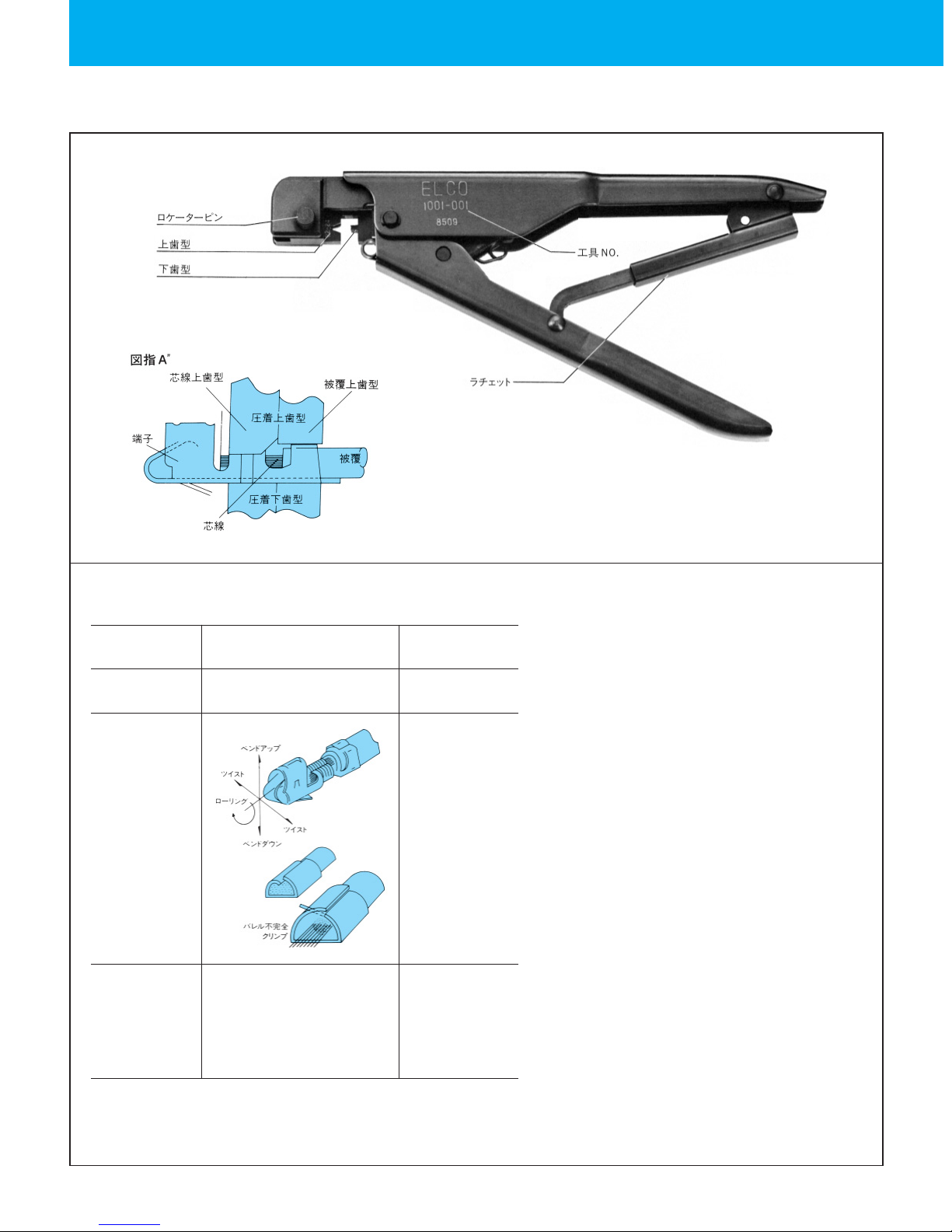
Structure of the Tool and Part Names
With this tool, a strip of contacts can be crimped easily with the applicable wire
by using a set of crimper and anvil. (No need to replace the crimper and anvil.)
Example of Failure
Selecting the appropriate crimper
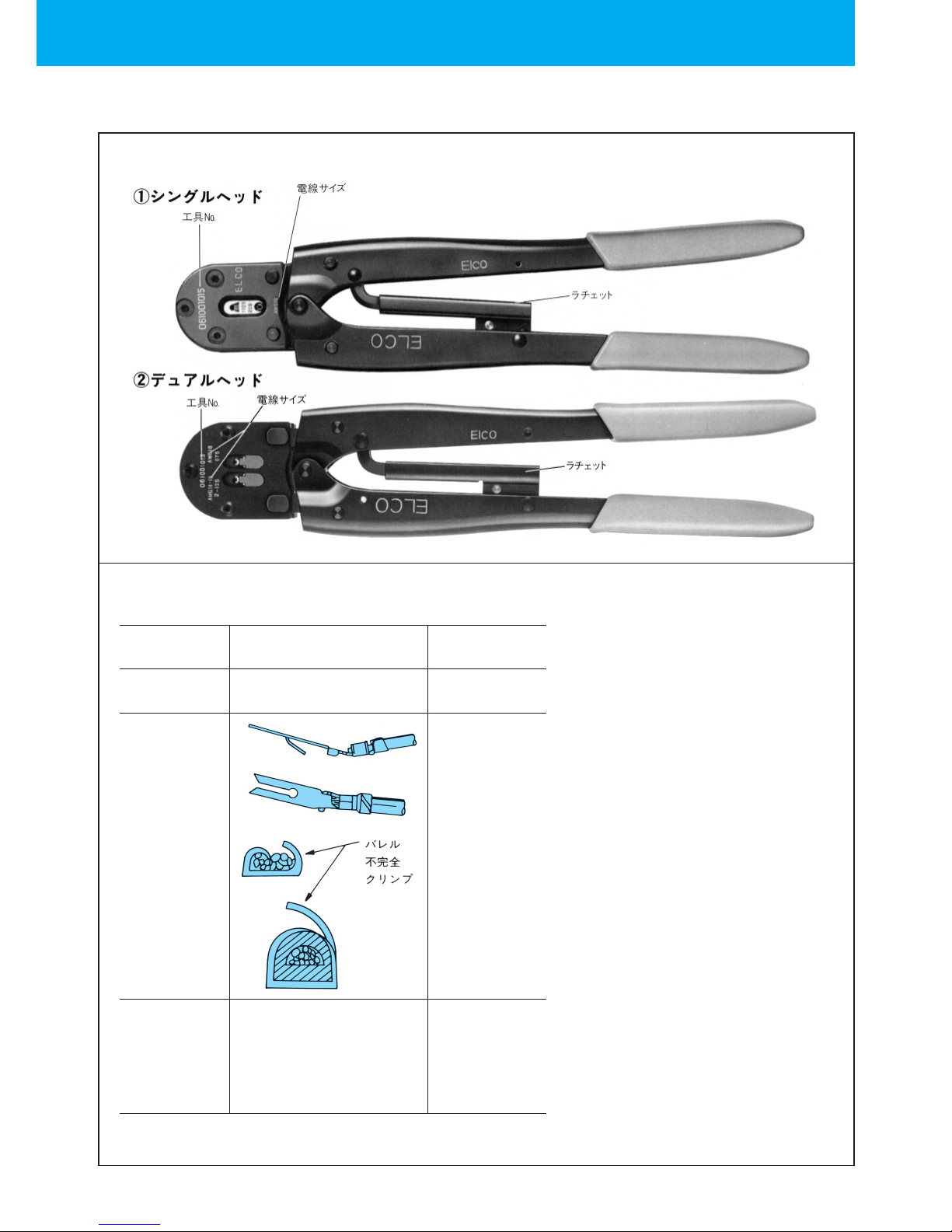
1.Requisite blades are attached on top and bottom of the crimper.
2.The number of applicable size of the wire is engraved on the crimper.
3.Select the crimper to the size of the wire.
4.When replacing the crimper, pull out the locator pin.
(The locator pin can be pulled out with fingers easily.) で簡単に抜く事が出来ます。
5.Install the appropriate crimper and fix it with the locator pin.
Procedures
1.Make sure that the tool number and the wire size are met.
2.Cut the strip of contacts in 20cm.
3.Insert the cut strip of contacts into the contact feed bar.
4.Feed the contacts to the proper position.
5.Strip the wire and insert the contact appropriately.
6.Close the grips until the latchet is released.
7.Open the grips to pick up the contact.
8.Feed the contact with stripped wire to the proper position.
9.Make sure that the shape of the crimped work is appropriate.
Failure Item Failure Description
Pull strength is out of specification.
1)Malformation of
the crimped area
(
Wire barrel)
1.Bend
2.Twist
3.Deformation
工具クリンプ位置が一定でない場合
珎クリンプハイトの
バラツキ
Cause
The wire size is out of
用又は工具の摩耗
歯型に対し端子が中心
にセットされていない
ラチェット の摩耗及び
変形により、ハンドルを
完全に締付けない位置
(中間位置)、で も復帰
する状態となっている
場合に起きる
Locator pin
Tool identification number
Ratchet
Locator pin
Crimper
Crimper fixing screw
Contact feed bar
Anvil
Crimper
Head
Movable cutter
Fixing screw
Anvil Grip
Shaft pin
Wire crimping part
Wires
Cladding insulator crimping part
2)Deformation of
the terminal
3.Deformation
of the barrel
Cause
The wire size is out of
the specification, or
abrasion of the tool
The terminal is not
set in position against
the crimper and anvil.
3)Variation in
crimp height The crimping height
of the tool is not fixed.
Occurred when grips
are incompletely
tightened (tightened
half way) but in the
position where they can
be open due to the
abrasion or deformation
of the ratchet.
Bent up
twist
twist
ト
Bent down
Rolling
Incomplete crimping
of the barrel