INSTRUCTIONMANUAL
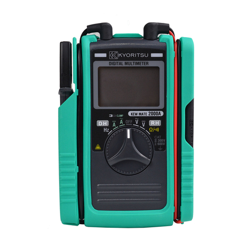
KEW MATE 2000/2001
DIGITAL MULTIMETER
WITH
AC/DC CLAMP SENSOR
KYORITSU ELECTRICAL INSTRUMENTS
WORKS, LTD.
1.SAFETY WARNINGS
ThisinstrumenthasbeendesignedandtestedaccordingtoIECPublication61010:
SafetyRequirementsforElectronicMeasuringApparatus. Thisinstructionmanual
containswarningsandsafetyruleswhichmustbeobservedbytheusertoensure
safeoperationoftheinstrumentandtoretainitinsafecondition.Therefore,read
throughtheseoperatinginstructionsbeforestartingusingtheinstrument.
WARNING
●
Read through and understand instructions contained in this manual before
startingusingtheinstrument.
●
Save and keep the manual handy to enable quick reference whenever
necessary.
●
Be sure to use the instrument only in its intended applications and to follow
measurementproceduresdescribedinthemanual.
●
Besuretounderstandandfollowallsafetyinstructionscontainedinthemanual.
Failure to follow the above instructions may cause injury, damage to the instrument
and/ordamagetoequipmentundertest.
Thesymbol indicatedontheinstrumentmeansthattheuser must refer to related
partsofthemanualforsafeoperationoftheinstrument.Besuretocarefullyreadthe
instructionsfollowingeach symbolinthismanual.
DANGER
isreservedforconditionsandactionsthatarelikelytocauseseriousorfatal
injury.
WARNING
isreservedforconditionsandactionsthatcancauseseriousorfatalinjury.
CAUTION
is reserved for conditions and actions that can cause minor injury or
instrumentdamage.
Following symbols are used on the instrument and in the instruction manual. Attention
shouldbepaidtoeachsymboltoensureyoursafety.
Refertotheinstructionsinthemanual.
Thissymbolismarkedwheretheusermustrefertotheinstructionmanualsoasnot
tocausepersonalinjuryorinstrumentdamage.
Indicatesaninstrumentwithdoubleorreinforcedinsulation.
Indicatesthatthisinstrumentcanclamponbareconductorswhenmeasuring
avoltagecorresponding totheapplicableMeasurement category,whichismarked
nexttothissymbol
.
IndicatesAC(AlternatingCurrent)
.
IndicatesDC(DirectCurrent).
IndicatesACandDC.
DANGER
●
Never make measurement on circuits with a maximum voltage difference of
600VAC/DCorgreaterbetweenconductors(300VAC/DCorgreaterbetweena
conductorandground).
●
Do not attempt to make measurement in the presence of flammable gasses.
Otherwise, the use of the instrument may cause sparking, which leads to an
explosion.
●
Neverattempttousetheinstrumentifitssurfaceoryourhandiswet.
●
Donotexceedthemaximumallowableinputofmeasuringranges.
●
Neveropenthebatterycompartmentcoverwhilemakingmeasurement.
●
Never try to make measurement if any abnormal conditions, such as broken
Transformerjawsorcaseisnoted.
●
The instrument is to be used only in its intended applications or conditions.
Otherwise, safety functions equipped with the instrument doesn
t work, and
instrumentdamageorseriouspersonalinjurymaybecaused.
WARNING
●
Neverattemptto make anymeasurement,if anyabnormalconditions are noted,
suchasbrokencase,crackedtestleadsandexposedmetalparts.
●
Donotturn theFunctionSelector Switchwhilethe testleads areconnectedto
thecircuitundertest.
●
Donotinstallsubstitutepartsormakeanymodificationtotheinstrument.Return
theinstrumenttoKyoritsuoryourdistributorforrepairorre-calibration.
●
Donottrytoreplacethebatteriesifthesurfaceoftheinstrumentiswet.
●
Alwaysdisconnecttheclampsensorandthetestleadsfromthecircuitundertest
andswitchoffthe instrument before openingthebatterycompartment cover for
batteryreplacement.
CAUTION
●
Make sure that the Function Selector Switch is set to an appropriate position
beforemakingmeasurement.
●
Alwaysmakesure to placethetest leads inthetest lead holderbeforemaking
currentmeasurement.
●
Donotexposetheinstrumenttothedirectsun,extremetemperaturesordewfall.
●
Be sure to set the Function Selector Switch to the "OFF" position after use.
Whentheinstrumentwillnotbeusedforalongperiodoftime,placeitinstorage
afterremovingthebatteries.
●
Use a damp cloth and detergent for cleaning the instrument. Do not use
abrasivesorsolvents.
Measurement Category:
To ensure safe operation of measuring instruments, IEC 61010 establishes safety
standardsforvariouselectricalenvironments,categorizedasOtoCAT.IV,andcalled
measurement categories. Higher-numbered categories correspond to electrical
environments with greater momentary energy, so a measuring instrument designed
for CAT.III environments can endure greater momentary energy than one designed
forCAT.II.
O :Circuitswhicharenotdirectlyconnectedtothemainspowersupply.
CAT.II :ElectricalcircuitsofequipmentconnectedtoanACelectricaloutletbya
powercord.
CAT.III :Primary electrical circuits of the equipment connected directly to the
distributionpanel,andfeedersfromthedistributionpaneltooutlets.
CAT.IV :Thecircuitfromtheservicedroptotheserviceentrance,andtothepower
meterandprimaryover-currentprotectiondevice(distributionpanel).
2.FEATURES
●
Permits AC/DC current measurement up to 60A using a clamp sensor that comes
standardwiththeinstrument
●
Clampsensorforeaseofuseincrowdedcableareasandothertightplaces
●
Permitscurrentmeasurementwithanopencurrent-clampsensorthatdoesnotrequire
openingandclosingoperationsbytheuser
●
Auto-power-savefunction
●
Buzzerforeasycontinuitychecking
●
Dataholdfunctiontofreezethereadings
●
LCDwitha3400countfullscalebargraph
●
Shockabsorbingholsterforeaseofstorage
●
Designed to international safety standard IEC61010-1: measurement category
CAT.
Ⅲ
,300Vandpollutiondegree2.
O: Device which is
not directly
connected to the
mains power supply
3.SPECIFICATIONS
●
MeasuringRangesandAccuracy(at23
℃±
5
℃
,relativehumidity75%orless)
※
Electromagnetic
RFfield
≦
1V/m
compatibility
ACV/DCV/OHMS/FREQUENCYtotalaccuracy=specifiedaccuracy
(IEC61000-4-3)
ACA/DCA
totalaccuracy=specifiedaccuracy+5dgt
RF transmitters such as mobile telephones may not be used in close
proximity.
●
SafetyStandard IEC61010-1
measurementCAT.
Ⅲ
,300V,pollutiondegree2
measurementCAT.
Ⅱ
,600V,pollutiondegree2
IEC61010-031
IEC61010-2-032,IEC61010-2-033
IEC61326-1(EMC),EN50581(RoHS)
●
OperatingSystem Dualintegration
●
Display Liquid crystal display with maximum reading of 3399 as
wellasunitsandannunciators
Bargraphwithmaximumpointsof33
●
OverInputIndication "OL"ontheLCD(
Ω
rangesonly)
●
Auto-rangingOperation Shiftstothenexthigherrangewhen bargraph increases
to33points
Shiftstothe nextlower rangewhenbar graphdecreases
to3points
●
SampleRateNumericreading:about400ms,
bargraph:about20ms
MODEL
2000
2001
Range
60A
100A
ACCurrent
A
DCCurrent
A
ACVoltage
V
Inputimpedance:10M
Ω
DCVoltage
VInputimpedance:10M
Ω
MeasuringRange
0-60.0A
0-100.0A
Accuracy
±
2.0%rdg
±
5dgt(50/60Hz)
±
2.0%rdg
±
5dgt(50/60Hz)
MODEL
2000
2001
Range
60A
100A
MeasuringRange
0-
±
60.0A
0-
±
100.0A
Accuracy
±
2.0
%
rdg
±
5dgt
±
2.0
%
rdg
±
5dgt
Range
3.4V
34V
340V
600V
MeasuringRange
0-600V
(Auto-ranging)
Accuracy
±
1.5%rdg
±
5dgt(50-400Hz)
Range
340mV
3.4V
34V
340V
600V
MeasuringRange
0-
±
600V
(Auto-ranging)
Accuracy
±
1.5%rdg
±
4dgt
Resistance
Ω/
Range
340
Ω
3.4k
Ω
34k
Ω
340k
Ω
3.4M
Ω
34M
Ω
MeasuringRange
0-33.99M
Ω
(Auto-ranging)
Accuracy
±
1.0%rdg
±
3dgt
Buzzerbeepsbelow30
±
10
Ω
(
Continuity buzzer works on 340
Ω
range
only
)
±
5%rdg
±
5dgt
±
15%rdg
±
5dgt
Frequency
Hz
Range
Current
Voltage
MeasuringRange
0-3.399kHz
3.4kHz-10kHz
(Auto-ranging)
0-3.399kHz
3.4kHz-33.99kHz
34kHz-300kHz
(Auto-ranging)
Accuracy
±
0.1%rdg
±
1dgt
±
0.1%rdg
±
1dgt
●
Locationforuse Indooruse,Altitudeupto2000m
●
Accuracy-insured 23
℃±
5
℃
,relativehumidity75%orless
Temperatureand (withoutcondensation)
HumidityRanges
●
OperatingTemperature 0-40
℃
,relativehumidity85%orless
andHumidityRange (withoutcondensation)
●
StorageTemperature -20-60
℃
,relativehumidity85%orless
andHumidityRange (withoutcondensation)
●
Source Two1.5VDCR03(UM-4)batteries
●
CurrentConsumption Approx.10mA
●
Power-saveFunction Shiftstothepower-savestateabout10minutesafterthe
lastswitchoperation
(currentconsumption:approx.10
μ
A)
●
OverloadProtection AC/DCcurrentranges:MODEL2000 AC/DC 72A for 10
seconds
AC/DCcurrentranges:MODEL2001 AC/DC
120
A for
10seconds
AC/DCvoltageranges:AC/DC720Vfor10seconds
Resistanceranges:AC/DC720Vfor10seconds
Frequencyranges:AC/DC720Vfor10seconds
●
WithstandVoltage AC3470V for 5 sec. between electrical circuit and
housingcase
●
InsulationResistance 10M
Ω
orgreaterat1000Vbetweenelectricalcircuitand
housingcase
●
ConductorSize MODEL2000Approx.
6mmdiametermax.
MODEL2001Approx.10mmdiametermax.
●
Dimensions MODEL2000128(L)
×
87(W)
×
24(D)mm
MODEL2001128(L)
×
92(W)
×
27(D)mm
●
Weight MODEL2000Approx.210g
MODEL2001Approx.220g
●
AccessoriesTwoR03(UM-4)batteries
InstructionManual
4.INSTRUMENT LAYOUT
Data Hold Button
MODEL2001 MODEL2000
Range Hold Button
Test Lead
LCD Display
AC/DC Clamp Sensor
DCA
Zero Adjust
Knob
Digital Multimeter
Function Selector Switch
Holster
Barrier Barrier
AC/DC
Battery Voltage Warning
Auto Range
Data Hold
Unit
Bar Graph
Buzzer
Manual
Range
Wind the lead around the folder.
Test Leads
AC/DC Clamp Sensor
5.PREPARATIONS FOR MEASUREMENT
(
1
)
Checkingbatteryvoltage
SettheFunctionSelectorSwitchtoanypositionotherthantheOFFposition.
Ifthemarksonthedisplayisclearlylegiblewithoutsymbol
"BATT"
showing,battery
voltage is OK. If the display blanks or
"BATT"
is indicated, replace the batteries
accordingtosection
8: Battery Replacement
.
NOTE
Whentheinstrumentisleftpoweredon,theauto-power-savefunctionautomatically
shutthepoweroff;ThedisplayblankseveniftheFunctionSelectorSwitchissetto
apositionotherthan the OFF positioninthisstate. To poweronthe instrument,
turntheFunctionSelectorSwitchorpresstheDataHoldButton.Ifthedisplaystill
blanks,thebatteriesareexhausted.Replacethebatteries.
(
2
)
MakesurethattheFunctionSelectorSwitchissettotheappropriaterange.
Also make sure that data hold function is not enabled. If inappropriate range is
selected,desiredmeasurementcannotbemade.
(
3
)
InstallTestLeadtotheHolsteronthesideofbody
ItispossibletomeasurewithseeingtheLCDDisplaykeep
TestLeadinstallingtotheHolster.
6.HOW TO MAKE MEASUREMENT
6-1 Current
Measurement
DANGER
●
Inordertoavoidpossibleshockhazard,nevermakemeasurementoncircuitswith
a maximum voltage difference of 600VAC/DC or greater between conductors
(300VAC/DCorgreaterbetweenaconductorandground).
●
Donotmakemeasurementwiththetestleadsconnectedtothecircuitundertest.
Nevermakemeasurementwiththebatterycompartmentcoverremoved.
●
Keepyourfingersandhandsbehindthebarrierduringmeasurement.
CAUTION
●
Whenhandlingtheclampsensor,exercisecautionnottoapplyexcessiveshocks
orvibrationtothesensor.
●
M
aximum measurable conductor size is MODEL2000 6mm / MODEL2001
10mmindiameter.
AC/DC
Battery Voltage Warning
Auto Range
Data Hold
Unit
Bar Graph
Buzzer
Manual
Range
Wind the lead around the folder.
Test Leads
AC/DC Clamp Sensor
6-1-1DCCurrentMeasurement
(1)TheFunctionSelectorSwithtothe"
A"position.
("DC"and"AUTO"marksareshownonthetopofthedisplay.)
(2)Turnthe0(Zero)ADJknobtosetthereadingofthemultimetertozero.(Ifthiszero
adjustmentismadeincorrectly,measurementerrorswillresult.)
(3)Adjustoneoftheconductorstothecenteroftheclampsensor'sarrow.
( When the position of the conductor is not at the center of the arrow, the error
occurs.)
Measuredvalueisshownonthedisplay.
Note:Whencurrentflowsfromtheupsidetotheundersideoftheinstrument,thepolarity
ofthereadingispositive(+).Otherwise,thepolarityofthereadingisnegative(-).
6-1-2ACCurrentMeasurement
(1)SettheFunctionSelectorSwitchto"
A."
("AC"and"AUTO"marksareshownonthetopoftheLCD.)
(2)Adjustoneoftheconductorstothecenteroftheclampsensor'sarrow.
( When the position of the conductor is not at the center of the arrow, the error
occurs.)
Measuredvalueisshownonthedisplay.
Note:UnlikeDCcurrent measurement, zeroadjustmentisnot necessary. Thereis not
polarityindicationeither.
6-2 Voltage Measurement
DANGER
●
In order to avoid possible shock hazard, never make measurement on circuits
with a maximum voltage difference of 600VAC/DC or greater between
conductors(300VAC/DCorgreaterbetweenaconductorandground).
●
Donotmakemeasurementwiththebatterycompartmentcoverremoved.
●
Keepyourfingersandhandsbehindthebarrierduringmeasurement.
6-2-1DCVoltageMeasurement
(1)SettheFunctionSelectorSwitchto"
V."
(
"DC"and"AUTO"marksareshownonthetopoftheLCD.
)
(2)Connecttheredtestleadtothepositive(+) sideofthecircuitundertestandthe
blacktestlead tothenegative (-)side. Measuredvoltagevalue is shownonthe
display.
Whentheconnectionisreversed,"-"isshownonthedisplay.
6-2-2ACVoltageMeasurement
(1)SettheFunctionSelectorSwitchto"
V."
(
"AC"and"AUTO"marksareshownontheLCD.
)
(2)Connectthetestleadstothecircuitundertest.
Measuredvoltagevalueisshownonthedisplay.
6-3 Resistance Measurement
DANGER
●
Nevermakemeasurementoncircuitsthatarelive.
●
Nevermakemeasurementwiththebatterycompartmentcoverremoved.
●
Keepyourfingersandhandsbehindthebarrierduringmeasurement.
Conductor
MODEL2000 MODEL2001
Adjust a
conductor to
the center of
the arrow.
Correct Wrong
(1)SettheFunctionSelectorSwitchto"
Ω/
."
(2)Checkthatthedisplayshowsover-range.Shortthetest leadsand checkthatthe
buzzerbeepsandthedisplayreadszero.
(3)Connect the test leads to the circuit under test. Measured resistance value is
shownonthedisplay.Whenthemeasuredvalueisbelowabout30
Ω
,thebuzzer
beeps.
Note:When the test leads are shorted, the display may read a small resistance value.
Thisistheresistanceofthetestleads.
Ifthereisanopenineitherofthetestleads,"OL"isshownonthedisplay.
Onthe340
Ω
range,"
"isshownontheleftsideoftheLCD.
6-4 Frequency Measurement
DANGER
●
Inordertoavoidpossibleshockhazard,nevermakemeasurementoncircuitswith
a maximum voltage difference of 600VAC/DC or greater between conductors
(300VAC/DCorgreaterbetweenaconductorandground).
●
Donotmakemeasurementwiththetestleadsconnectedtothecircuitundertest.
Nevermakemeasurementwiththebatterycompartmentcoverremoved.
●
Do not make current measurement with the test leads connected to the circuit
undertest.
●
Keepyourfingersandhandsbehindthebarrierduringmeasurement.
(1)SettheFunctionSelectorSwitchto"Hz."
(2)Measuringfrequencyofcurrent:
Adjustoneoftheconductorstothecenteroftheclampsensor'sarrow.Measured
valueisshownonthedisplay.
Measuringfrequencyofvoltage:
Connectthetestleadstothecircuitundertest.Measuredfrequencyisshownon
thedisplay.
Note:Measuringrangeofcurrentfrequency is0-10kHzwithminimummeasurableinput
ofMODEL200015A
(
Typ
)
/MODEL200125A
(
Typ
)
.
Measuring range of voltage frequency is 0-300kHz with minimum measurable
inputof30V
(
Typ
)
.
Whenmeasuringfrequency,donotattachtheclampsensorandthetestleadsto
thecircuitundertestsimultaneously.
7.OTHER FUNCTIONS
7-1Auto-Power-SaveFunction
NOTE
Asmallamountofcurrentisconsumedeveninthepower-savestate.Makesureto
settheFunctionSelectorSwitch to the OFFpositionwhentheinstrument is not
used.
Prohibition
This function helps to avoid unwanted exhaustion of the batteries because of
leaving the instrument powered on and extend battery life. The instrument
automatically shifts to the power-save state about 10 minutes after the last
FunctionSelectorSwitchorotherswitchoperation.
Toreturnto the normalstate: Turn theFunctionSelector Switch orpressthe
Data Hold Button twice to exit the power-save state and enable measurement
functions.
7-2DataHoldFunction
This is a function to freeze a measured value on the display. Press the Data
HoldButtononcetoholdthecurrentreading.Inthisdataholdstate,thereading
isheldevenifinputvaries."H"and"
"marksareshownontheLCDinstead
of"AUTO"mark.
Toexitthedataholdstate,presstheDataHoldButtonagain.
7-3RangeHoldFunction
The instrument defaults to auto-ranging ("AUTO" is shown on the LCD).
PressingtheRangeHoldButton enablesmanual selectionamongmeasurement
ranges
(
"
"markisshownontheLCDinsteadof"AUTO"mark
)
PresstheRangeHoldButtontoselectahigherrange.
To switch from manual range selection to auto-ranging, press down the Range
Hold Button for about one seconds, or turn the Function Selector Switch to
anotherpositionbeforesettingitbacktothecurrentrange.
8.BATTERY REPLACEMENT
WARNING
●
Inorderto avoid possibleshockhazard, always disconnectthetestleads from
thecircuitundertestandsettheFunctionSelectorSwitchto theOFFposition
beforetryingtoreplacethebatteries.
CAUTION
●
Donotmixnewandoldbatteries.
●
Install batteries in the orientation as shown inside the battery compartment,
observingcorrectpolarity.
Whenthebatteryvoltagewarningmark"BATT"isshownonthetopleftcornerofthe
LCD, replace the batteries. Note that the display blanks and "BATT" mark is not
shownifthebatteriesarecompletelyexhausted.
(1)SettheFunctionSelectorSwitchto"OFF."
(2)Removetheinstrumentfromtheholster.
(3)Loosen the battery-compartment-cover-fixing screw on the lower back of the
instrument.
(4)ReplacethebatterieswithtwonewR03(UM-4)1.5Vbatteries.
(5)Putthebatterycompartmentcoverbackinplaceandtightenthescrew.
Screw
Battery
Compartment
Cover
Batteries
92-1507E8-16
DISTRIBUTOR
Kyoritsu reserves the rights to change specifications or
designs described in this manual without notice and without
obligations.


