KYOWA EDX-10B User manual

IM-A-1068 December, 2015
INSTRUCTION MANUAL
EDX-10B
Compact Recording System
(FOR HARDWARE)
Thank you for purchasing KYOWA’s product EDX-10B Compact Recording
System.
Read this Instruction Manual carefully in order to make full use of the high
performance capabilities of the product.
Do not use the product in methods other than described in this Manual.
This Manual only describes hardware operation of the EDX-10B. For the
Dynamic Data Recording Software DCS-100A, see the DCS-100AInstruction
Manual (For EDX-10A/B Operation).
Microsoft and Windows are either registered trademarks or trademarks of Microsoft Corporation in the United States and/or
other countries.
Generally, company names and trade names described in this Instruction Manual are trademarks or registered trademarks of
the companies.
This Instruction Manual may not be copied or reproduced, in whole or part, without consent of KYOWA.
Copyright © Kyowa Electronic Instruments Co., Ltd. All rights reserved.
The contents of the Instruction Manual are subjected to change without prior notice.
We assume no responsibility whatever for any damage resulting from the use of this product.


1
CONTENTS
CONTENTS ................................................................................. 1
STANDARD ACCESSORIES ................................................................... 2
OPTIONALACCESSORIES .................................................................... 2
SAFETY PRECAUTIONS (Do not forget to read the safety precautions prior to use.)...................... 3
LIMITED LIFE PARTS AND PREVENTIVE MAINTENANCE ........................................ 6
EDX-10B REPLACEMENT BEFORE THE END OF SERVICE LIFE ................................... 6
NOTATIONS USED IN THE INSTRUCTION MANUAL ............................................. 6
IMPORTANT PRECAUTIONS WHEN USING EDX-10B............................................. 7
CE MARKING ............................................................................... 7
SURFACE APPEARANCE ..................................................................... 7
1. OUTLINE OF THE PRODUCT ................................................................ 8
1-1. OUTLINE OF THE PRODUCT ............................................................ 8
1-2. FEATURES ............................................................................ 8
1-3. MODELS .............................................................................. 8
2. CONTROLS AND INDICATORS .............................................................. 9
2-1. FRONT................................................................................ 9
2-2. SIDE.................................................................................. 9
2-3. BOTTOM............................................................................. 10
3. CONNECTION AND DEFAULT SETTING ..................................................... 11
3-1. PROCEDURES FOR MEASUREMENTS ................................................... 11
3-2. CONNECT THE MEASURING UNITS..................................................... 12
3-2-1.NUMBER OF CONNECTABLE MEASURING UNITS..................................... 12
3-2-2. HOW TO CONNECT THE MEASURING UNIT ........................................ 13
3-3. CONNECT SENSORS .................................................................. 13
3-4. CONNECT THE OPTIONALAC ADAPTER ................................................ 14
3-5. INSTALLING THE USB DEVICE DRIVER................................................. 15
3-6. CONNECTING THE USB INTERFACE .................................................... 16
3-6-1. Connect the USB cable............................................................... 16
3-6-2. Wiring diagram of the USB interface .................................................... 17
4. MEASURE DATA.......................................................................... 19
4-1. PROCEDURE ......................................................................... 19
4-2. EDX-10B POWER ON/OFF .............................................................. 19
5. TROUBLE SHOOTING ..................................................................... 20
6. MAINTENANCE .......................................................................... 21
7. SPECIFICATIONS ......................................................................... 22
8. OUTSIDE DRAWING ...................................................................... 23
8-1. EDX-10B ............................................................................. 23
8-2. WHEN CONNECTING FOUR EDX-11A UNITS ............................................. 24

2
This Manual only describes hardware operation of the EDX-10B.
STANDARD ACCESSORIES
The following accessories are packed with the EDX-10B.
When unpacking, check the contents to ensure that all accessories are enclosed.
DYNAMIC DATA RECORDING SOFTWARE DCS-100A:
・・・・・・
1 (CD-R)
Ground wire P-72:
・・・・・・・・・・・・・・・・・・・・・・・・・・・・・・・・・・・・・・・
1
USB cable N-38:
・・・・・・・・・・・・・・・・・・・・・・・・・・・・・・・・・・・・・・・・・
1
Rubber Foot:
・・・・・・・・・・・・・・・・・・・・・・・・・・・・・・・・・・・・・・・・・・・
8
Test Certificate and Warranty:
・・・・・・・・・・・・・・・・・・・・・・・・・・・・・・
1 each
EDX-10B READ IN THE BEGGNING (English/Japanese)
・・・・・・・
1
EDX-10B READ IN THE BEGGNING (Chinese)
・・・・・・・・・・・・・
1
OPTIONALACCESSORIES
AC adapter:
・・・・・・・・・・・・・・・・・・・・・・・・・・・・・・・・・・・・・・・・・・・・・・
UN310-0515
Strain measuring unit:
・・・・・・・・・・・・・・・・・・・・・・・・・・・・・・・・・・・・
EDX-11A
Voltage measuring unit:
・・・・・・・・・・・・・・・・・・・・・・・・・・・・・・・・・・・・
EDX-12A
Thermocouple measuring unit:
・・・・・・・・・・・・・・・・・・・・・・・・・・・・・・・
EDX-13A
Low power strain measuring unit:
・・・・・・・・・・・・・・・・・・・・・・・・・・・・・
EDX-14A
Low power strain / voltage measuring unit:
・・・・・・・・・・・・・・・・・・・・・
EDX-15A
Dynamic Data Acquisition Software:
・・・・・・・・・・・・・・・・・・・・・・・・・・
DAS-200A

3
SAFETY PRECAUTIONS (Do not forget to read the safety precautions prior to use.)
The EDX-10B is designed to be used according to "7. SPECIFICATIONS."
Do not use the EDX-10B in an environment exceeding the specifications.
Or, system failure may result in.
PRIOR TO USE
For safe use of the EDX-10B, do not forget to read the “Safety Precautions” prior to use.
Kyowa Electronic Instruments Co., Ltd. assumes no liability for any damage resulting from the user’s failure to comply
with the safety precautions.
For safety operation of the EDX-10B, the following symbol mark is attached to the EDX-10B.
Indicates “PROTECTIVE GROUND TERMINAL.”
Be sure to connect the GND terminal to the ground.
SAFETY SYMBOLS
For safety operation of the EDX-10B, the following symbol marks are used in the Instruction Manual.
WARNING
Improper operation of the system may result in death or severe
injury of the operator.
CAUTION
Improper operation of the system may result in injury of the
operator and physical damage of the system.
WARNING
WARNING
Be sure to observe the warning and precautions described in the EDX-10B Instruction Manual (FOR
HARDWARE).
Power Supply
To prevent a fire hazard, when using the optional AC adapter, check the voltage range of theAC power outlet
before connecting.
Protective Ground
Be sure to connect the GND terminal. Or, it may cause electric shock, lower the performance and cause
trouble.
Avoid using in environment with inflammable gas, etc.
To prevent the risk of fire hazard or explosion, do not use the EDX-10B in environment with inflammable
gas, vapor, or dust.
If any trouble occurs
To prevent fire hazards, if smoke is emerging from the EDX-10B, immediately disconnect the USB cable or
AC adapter to terminate the system operation.

4
CAUTION
●CAUTION
Be sure to observe the caution and precautions described in the EDX-10B Instruction Manual (FOR
HARDWARE).
Do not use the EDX-10B outdoors.
Or, it may cause electric shock, fire hazard, lower the performance and cause trouble.
Use the EDX-10B within temperature ranging from 0 to 40ºC.
Use at temperatures exceeding the specified range may lower the performance and cause trouble.
If use under direct sunlight or in a cold place is inevitable, prepare a sunscreen or take proper measures to keep
it warm.
Use the EDX-10B in the specified operating humidity of 20 to 85% RH.
Use in a humid place exceeding the specified range or where it is exposed to splashing water may lower the
performance and cause trouble.
Do not use the EDX-10B immediately after the change in the environment.
Leave the EDX-10B as it is to acclimate to the environment.
Abrupt change in ambient temperature due to transportation, etc. may cause dew condensation, which may
result in lower performance and troubles.
Do not use the EDX-10B where it is subject to significant vibration or impact.
The vibration resistance and impact resistance are as follows.
Vibration resistance: 29.42m/s2(3G), 5 to 200Hz (when operating)
Impact Resistance: 294m/s2(30G)/11msec
Use the EDX-10B in an area where vibration and impact can be kept within the scope of specifications.
Continuous vibration or severe impact may cause deteriorated performance and system failure.
Do not use the EDX-10B in strong electromagnetic field.
Use the EDX-10B in an environment where magnetic field is acceptable to the PC.
Performance may be lowered and erroneous operation and troubles may result if it is used near a telemetry
system, microwave oven, electronic furnace or any other equipment generating a strong magnetic field.
Do not use the EDX-10B under poor conditions.
OptionalAC adapter (UN310-0515): 100 to 240 VAC (50 Hz/60 Hz) The power supply used for the EDX-10B
should not experience an instantaneous power failure and be free from noise.
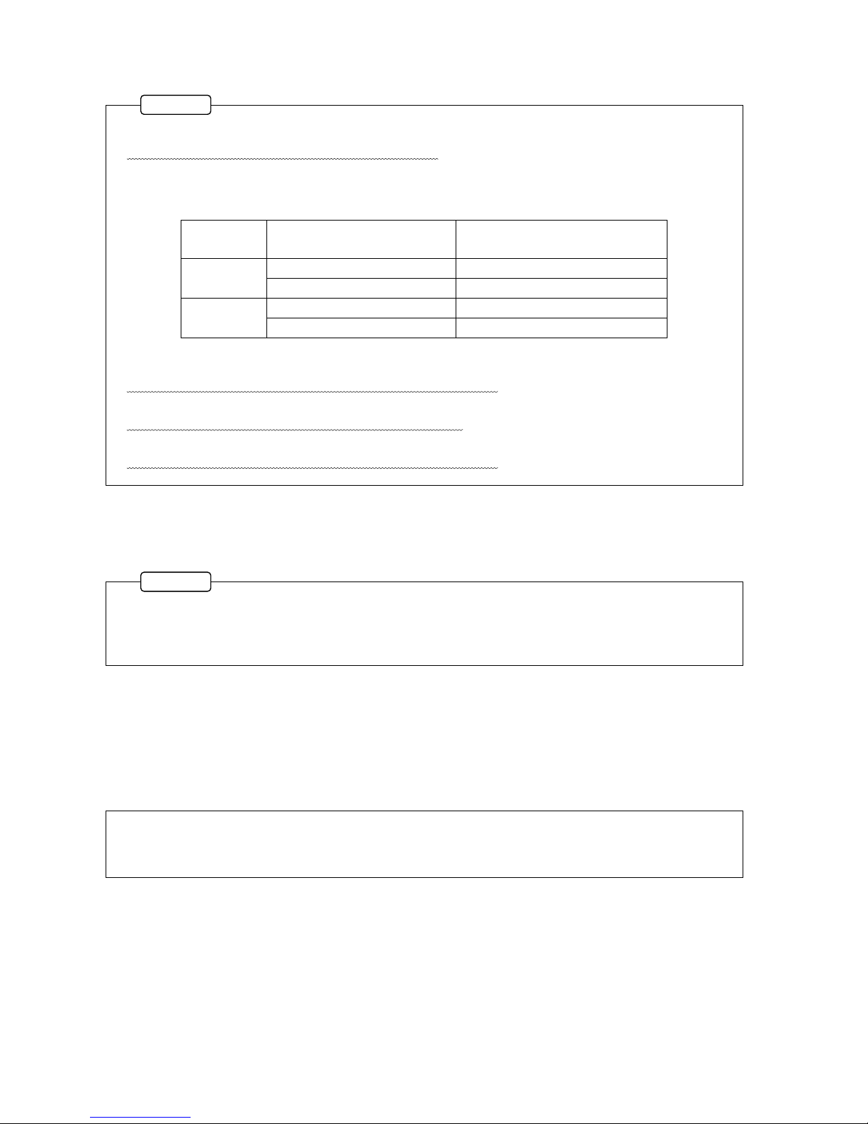
The specifications of the optionalAC adapter (UN310-0515) is as follows.
Input voltage: 100 to 240 VAC (50 Hz/60 Hz)
Output voltage: 5 VDC (1.5 A)
Operating Temperature Range 0 to 40℃
The optionalAC adapter (UN310-0515) is consumable item. Replace it every five years.
Do not connect the USB cable immediately after disconnecting.
Wait approximately 5 seconds before connecting the USB cable again.
Do not pull cables.
Lay cords and cables with a certain allowance so that unreasonable force is applied to the connections.
Pulling or unreasonable force may cause troubles or interrupt the measurement.
Avoid installing sensors and EDX-10B near a welding machine.
Failure to do so will pose the risk of erroneous data, malfunction and failure.
Do not disassemble or remodel the EDX-10B.
Disassembling or remodeling by user may cause electric shock hazards or damage the EDX-10B.
This warranty does not cover any damaged or defective parts that results from disassembling or remodeling.
Do not use the EDX-10B under dusty environment.
This can lead to performance problems and decreased operating efficiency.
Be careful that dust may not enter the EDX-10B not only during operation but also under stored conditions.
Preheat the EDX-10B before use.
After the power ON, always preheat the EDX-10B for approximately 10 minutes.

5
CAUTION
●Handle the CD-R with care.
Do not expose the CD-R to direct sun light, high temperature, or high humidity.
Do not apply pressure to the CD-R by laying object or bending.
Handle with care to avoid any fingerprint, dirt, scratch on both sides.
●Cleaning.
When the product gets dirty, clean the product with a dry soft cloth. When dust exists inside the
EDX-10B, clean it by using an air blow gun. Do not touch electronic parts.

6
Reference items required when handling the EDX-10B.
Essential precautions required when handling the EDX-10B.
LIMITED LIFE PARTS AND PREVENTIVE MAINTENANCE
The EDX-10B consists of various electronic components and those components, if not all, have a useful life.
Using them exceeding the years specified according to each part type (useful life) may affect the characteristics of the
EDX-10B, resulting in a malfunction or a failure.
You need to replace parts with a regular preventive maintenance schedule.
Limited life parts used with the EDX-10B are as follows.
Aluminum electrolytic capacitor
The signal-noise ratio will lower due to capacity low or smoke will be emitted due to liquid leak, resulting in a
malfunction of the EDX-10B.
AC adapter (optional accessories)
Heat and smoke will be emitted, resulting in an unstable voltage.
To operate the EDX-10B normally, finding a sign of the EDX-10B failure early by daily/periodic inspections and
taking the corrective action are required.
For inspection, contact KYOWA or our representatives.
*All components do age and will fail.
EDX-10B REPLACEMENT BEFORE THE END OF SERVICE LIFE
Preventive maintenance and replacement parts are a cost-effective way of keeping the performance and extending the
service life of the EDX-10B.
Regardless of the replacement parts, the EDX-10B itself gradually deteriorates with age.
Before the expected service life is reached, consider replacing the EDX-10B with a new one or the latest series as
preventive maintenance.
NOTATIONS USED IN THE INSTRUCTION MANUAL
Informational Notes
Certain notations are used as necessary to attract your attention to information that requires special care when
handing the EDX-10B, and to information provided for reference purposes.
Examples of Notations
NOTE
MEMO

7
1. Do not disconnect the USB cable and optionalAC adapter while recording data.
Or, it will cause data corruption and other problems
2. Do not connect multiple EDX-10B units to one PC. You can connect one EDX-10B per one PC.
3. When using the USB bus power, number of connectable measuring unit will change by USB standard and
type of measuring unit.
USB
standard
Type of measuring unit
Number of connectable
measuring unit
USB3.0
Use EDX-11A
Max 2 measuring unit
Not use EDX-11A
Max 4 measuring unit
USB2.0
Use EDX-11A
Max 1 measuring unit
Not use EDX-11A
Max 2 measuring unit
For details, see 3-2-1.NUMBER OF CONNECTABLE MEASURING UNITS.
4. Do not connect 5 or more measuring units.
Or, deterioration or malfunction of the instrument may result.
5. Be sure to use the accessory screws (binding head screw, M3 × 5) for coupling measuring units.
Longer screws will damage the inner PCB components.
6. Be sure to use standard accessory USB cable.
Or, deterioration or malfunction of the instrument may result.
1. Be sure to use standard accessory USB cable.
2. Be sure to use the optionalAC adapter (UN310-0515).
3. Be sure to connect the GND terminal to the ground.
Some products have a weld line often looks like a scratch or a line on the product appearance. It is
called a “weld line” which occurred during parts molding. Weld lines are not a crack or scratch. There
are no problems with the quality, performance and strength of the product.
IMPORTANT PRECAUTIONS WHEN USING EDX-10B
CE MARKING
SURFACE APPEARANCE
NOTE
NOTE

8
1. OUTLINE OF THE PRODUCT
1-1. OUTLINE OF THE PRODUCT
The EDX-10series are small and lightweight measuring instrument. Measuring units can be connected easily.
The EDX-10B can execute small-scale measurement of up to 16 channels by connecting 4 measuring units in
synchronous operation.
When connecting low power measuring unit, maximum 16 channels with 4 measuring unit can operate on USB bus
power. (When use USB3.0 port.)
The EDX-10B offers additional convenience for measurements because they are powered from the USB interface and
do not require a separate power supply.
1-2. FEATURES
Compact and lightweight
Stacking connectors enable easy connection and make synchronous cables unnecessary.
Since one measuring unit is capable of measurement of 4 channels and maximum 16 channels with 4 measuring units,
the EDX-10B is applicable for measurement in a wide range from a simple experiment to advanced measurement.
When using USB3.0 port, maximum 16 channels with 4 measuring unit can operate on USB bus power. (When not
used EDX-11A)
Applicable for high-speed measurement with the maximum sampling frequency of 20k Hz (up to 4 channels).
When connecting 4 measuring units (16 channels), the maximum sampling frequency is 5k Hz.
Connection with the PC is easy with the use of the USB interface.
You can measure and record data easily by using the Dynamic Data Recording Software DCS-100A.
The Dynamic DataAcquisition Software DAS-200Ais optional software that reproduces and analysis data after
recording.
1-3. MODELS
EDX-10series composed control unit EDX-10B and measuring units. There are five types of measuring unit.
EDX-11A that measure with strain gage type transducers, load, pressure, displacement, etc. EDX-15A is low power
strain measuring unit. EDX-12A is voltage measuring unit, which can measuring Voltage. EDX-15A is low power
strain / voltage measuring unit, which can measuring strain and voltage.
EDX-13A is thermocouple measuring unit, which can measuring temperature by thermocouple.
Table 1 EDX-10series models
Models
Name
EDX-10B
Control Unit
EDX-11A
Strain measuring unit
EDX-12A
Voltage measuring unit
EDX-13A
Thermocouple measuring unit
EDX-14A
Low power strain measuring unit
EDX-15A
Low power strain / voltage measuring unit

9
2. CONTROLS AND INDICATORS
2-1. FRONT
(1) [DC IN] connector
Used for connecting the optional AC adapter.
(2) LED
Lights up or blinks when connecting the PC, when communicating with the PC.
For details, see table 2-1.
(3) [USB] connector
USB interface connector
Used for connecting the PC.
(4) GND terminal
GND terminal
3 Be sure to connect the GND terminal to the ground.
Table 2-1 LED and operations
Status
Operation
Green
Light up
After starting up the Dynamic Data Recording Software DCS-100A.
Blink
When the EDX-10B is communicating with the PC.
Lights out
The Dynamic Data Recording Software DCS-100A is not working.
Red
Blink
Under the following conditions. When the LED lights up in red, stop using the
EDX-10B and disconnect the USB cable after disconnecting the optionalAC
adapter.
When the number of connected units exceeds the number of connectable units.
*The number of connectable units is refer to 3-2-1.NUMBER OF
CONNECTABLE MEASURING UNITS.
When connecting 5 or more measuring units.
Voltage range of the optionalAC adapter exceeds 4.5 to 5.5 V.
Voltage range of the USB bus power exceeds 4.5 to 5.5 V.
When an error occurs in the EDX-10B or in measuring units.
When detecting the overcurrent on the USB cable.
2-2. SIDE
(5) Fixing screw hole
For fixing the EDX-10B and measuring unit by using a screw.
(6) Finger slot
For connecting/disconnecting the EDX-10B and a measuring unit.
(7) Rubber foot slot
The EDX-10B has small rubber feet (optional) to keep it from sliding around
when placed on a flat surface.
(1)
(2)
(3)
(4)
(5)
(7)
(6)

10
2-3. BOTTOM
With Cap
With no Cap
(8) Rubber foot slot
The EDX-10B has small rubber feet (optional) to keep it from sliding around when
placed on a flat surface.
(9) Cap
Cap for protecting the unit-coupling connector on the EDX-10B bottom.
Remove the cap before connecting measuring units.
(10) Unit-coupling
Connector
Connector for connecting measuring units.
(8)
(10)
(9)

11
3. CONNECTION AND DEFAULT SETTING
3-1. PROCEDURES FOR MEASUREMENTS
This section describes necessary operations to be conducted prior to the actual measurements.
Section 3-2
Connect the measuring units
Connect the measuring units to the EDX-10B.
↓
Section 3-3
Connect sensors
Connect various sensors to the measuring units.
Section 3-4
Connect the optionalAC
adapter
Connect the optionalAC adapter.
Ground the GND terminal.
↓
Section 3-5
Installing the USB device
driver
Install the USB device driver into the PC.
↓
Section 3-6
Connect the USB interface
Set the USB interface for connecting the PC.
↓
Chapter 4
Measure data
Preparation and measure data.
For details, see 4.

12
3-2. CONNECT THE MEASURING UNITS
3-2-1.NUMBER OF CONNECTABLE MEASURING UNITS
The number of connectable measuring units is change by type of power and type of measuring units.
・When used optional AC adapter.
When used optionalAC adapter, the number of connectable measuring units is 4 units.
・When used USB bus power. (USB specification 3.0 )
When used USB3.0 bus power, the number of connectable measuring units is change by type of measuring units.
When used EDX-11A, the number of connectable measuring units is 2 units.
If you don’t use EDX-11A, the number of connectable measuring units is 4 units.
When used EDX-11A If you don’t use EDX-11A
・When used USB bus power. (USB specification 2.0 )
When used USB2.0 bus power, the number of connectable measuring units is change by type of measuring units.
When used EDX-11A, the number of connectable measuring units is 1 unit, only one EDX-11A.
If you don’t use EDX-11A, the number of connectable measuring units is 2 units.
When used EDX-11A If you don’t use EDX-11A
EDX-10B
Up to 4 units at any of
measuring units
任意の測定ユニットで
最大4台まで
EDX-10B
Up to 4 units at any of
measuring units
*Except EDX-11A
EDX-10B
Up to 1 unit at any of
measuring units
EDX-11A
EDX-10B
Only EDX-11A
EDX-10B
Up to 4 units at any of
measuring units
*Except EDX-11A

13
Be sure to use the accessory screws (binding
head screw, M3 × 5).
Longer screws will damage the inner PCB
components.
Tightening torque: 0.7 Nm or less
EDX-10B
Measuring Unit
(EDX-14A, etc.)
EDX-10B
Measuring Unit
(EDX-14A, etc.)
■Before connecting the USB cable, mount the cap to the unit-coupling connector of the very-bottom
measuring unit.
Or, it may cause system failures and accidents.
■When you use the optionalAC adapter, you can connect the measuring units up to 4 units.
Do not connect 5 or more measuring units.
Do not bend or twist the EDX-10B and the
measuring unit for connction.
Or, the holding pin and connectors on the
measuring unit will be damaged.
3-2-2. HOW TO CONNECT THE MEASURING UNIT
This section describes how to connect the measuring unit into the EDX-10B.
(1) Remove the cap on the EDX-10B bottom.
(2) Connect the unit-coupling connector on the EDX-10B bottom and connector on the measuring unit top.
Use the finger slots to connect the EDX-10B and a measuring unit.
(3) Fasten the accessory screws on both side of the measuring units.
3-3. CONNECT SENSORS
Before connecting the USB cable and optionalAC adapter, connect sensors to measuring units.
Connect sensors by referring to instruction manuals of the measuring units.
Remove the cap.
NOTE
Use the finger slot to grab the EDX-10B.
Fasten the screws.
NOTE
NOTE

14
When using the optionalAC adapter, check the voltage range of theAC power outlet before connecting.
Voltage range of the optionalAC adapter is 100 to 240 VAC (50 Hz/60 Hz). Be sure to keep the voltage
range.
Be sure to connect the GND terminal to the ground.
If the power supply voltage exceeds the above range or if a voltage between each terminal and the
grounding has a potential exceeding power supply voltage, do not connect the AC power cable to theAC
power outlet.
Or, it may cause system failures and accidents.
Be sure to connect the GND terminal to the ground.
Or, it may cause electric shock, lower the performance and cause
trouble.
AC power outlet
Within the range of
100 to 240 VAC
After connecting theAC adapter, connect the USB
cable.
3-4. CONNECT THE OPTIONALAC ADAPTER
Please connect the optional AC adapter. If you use the optional AC adapter, EDX-10B can connected four measuring
units.
*If you want to use USB bus power, plese go to 3-5.INSTALLING THE USB DEVICE DRIVER.
(1) Connect the DC plug of the optionalAC adapter into the [DC IN] connector of the EDX-10B.
(2) Connect the optionalAC adapter into the AC power outlet.
The power supply voltage should be checked according to the procedure described below.
(1) Use the tester to measure the voltage between the AC power
outlet terminals and ensure that the voltage is within the range
of 100 to 240 VAC.
(2) Use the testers to measure the voltage levels between the
ground and each of theAC power outlet terminals to ensure
that one voltage level is 0 V and the other is within the range of
100 V to 240 VAC.
(3) If the EDX-10B is used at job site where induction motors,
electric welder and other devices that generate noise are used,
power supply condition may be insufficient due to noise. It is
recommended to use KYOWA’s insulation transformer or noise
cut transformer.
NOTE
NOTE
AC adapter
UN310-0515
DC Plug
Be sure to connect the
GND terminal to the
ground.
Ground wire
P-72
NOTE

15
3-5. INSTALLING THE USB DEVICE DRIVER
Install the USB device driver into the PC before using the USB interface.
This section describes how to install the USB device driver.
(1) Please check that the PC is not connected to the EDX-10B by USB cable.
(2) Please log in as administrator.
(3) Insert the CD into the PC.
(4) Double-Click the “/UsbDriver/KYOWA_USB_****.exe” in the CD.
**** is version of driver.
(5) Follow the instruction on screen. Finish button appears when the setup completes.
(6) Please connect the PC to EDX-10B by USB cable. Installation of the USB driver will start.
For details, see Instruction Manual (FOR USB DRIVER SET UP) , which is in the same folder.

16
After connecting the USB cable and starting up the DCS-100A, when the LED blink in red, you
cannot control the EDX-10B from the PC. Solve the cause by checking the "Checked Items and
Countermeasures" in 5. TROUBLE SHOOTING.
When connecting multiple EDX-10B units to one PC, EDX-10B cannot measuring.
Do not connect other machine to USB port.
Or, deterioration or malfunction of the instrument may result.
3-6. CONNECTING THE USB INTERFACE
3-6-1. Connect the USB cable
(1) Connect the B connector of the USB cable into the [USB] connector of the EDX-10B.
(2) Connect theA connector into the USB port of the PC.
(3) Make sure the LED lights up in green after starting up the Dynamic Data Recording Software DCS-100A.
NOTE
EDX-10B cannot
measuring.
EDX-10B cannot
measuring.

17
USB hub
(commercially
available)
EDX-10B can connect max four measuring unit when usingAC adapter.
Be sure to useAC adapter when using USB hub, and USB cable length must be less than 5 m including an
USB hub.
When using USB bus power, you cannot use USB hub.
Or, deterioration or malfunction of the instrument may result.
Be sure to use standard accessory USB cable.
Or, deterioration or malfunction of the instrument may result.
3-6-2. Wiring diagram of the USB interface
(1) When connecting the PC and EDX-10B directly
(2) When connecting the PC and EDX-10B via USB hub
*Be sure to use AC adapter when using USB hub
Compliant to the
USB specification
2.0.
A connector
B connector
A connector
Mini B
connector
Use the high-speed USB hub compliant
to the USB specification 2.0
AC adapter
UN310-0515
Compliant to the
USB specification
2.0.
A connector
AC adapter
UN310-0515
B connector
USB cable
USB cable
NOTE

18
When using USB bus power, the number of connectable measuring unit is limited.
For detale, “3-2-1.NUMBER OF CONNECTABLE MEASURING UNIT”.
Be sure to use standard accessory USB cable.
Or, deterioration or malfunction of the instrument may result.
When using USB bus power, you cannot use USB hub.
Or, deterioration or malfunction of the instrument may result.
(3) When connecting the PC and EDX-10B directly. (Use USB bus power)
When you use USB bus power (USB specification 3.0 )
Use the high-speed USB hub
compliant to the USB
specification 3.0
A connector
B connector
USB cable
Use the high-speed USB hub
compliant to the USB
specification 2.0.
A connector
connector
B connector
USB cable
NOTE
Table of contents
Other KYOWA Recording Equipment manuals