KYOWA PCD-300B Assembly Instructions

IM-A-691c April 2010
SENSOR INTERFACE
PCD-300B
HARDWARE
INSTRUCTION MANUAL
Thank you for purchasing KYOWA’s product PCD-300B SENSOR
INTERFACE.
Read this Instruction Manual carefully in order to make full use of the high
performance capabilities of the product.
Do not use the product in methods other than described in this Manual.
In addition, this Instruction Manual is specified only for handling the PCD-300B
Hardware.
For details of the Software, customers are required to refer to the Software
Instruction Manual.
Windows2000/XP/Vista are registered trademarks of the Microsoft Corporation US.
NI DIAdem is a registered trade mark of the US National Instruments Corporation.
Generally, company names and trade names described in this Instruction Manual are trademarks or registered
trademarks of the companies.
Copyright © KYOWA ELECTRONIC INSTRUMENTS CO., LTD. All rights reserved.
This Instruction Manual may not be copied or reproduced, in whole or part, without consent of KYOWA.
The contents of the Instruction Manual are subjected to change without prior notice.

CONTENTS
STANDARD ACCESSORIES ..................................................................................................................................... 1
OPTIONALS ................................................................................................................................................................ 1
SAFETY PRECAUTIONS .......................................................................................................................................... 2
PRIOR TO USE............................................................................................................................................................................2
SAFETY SYMBOLS ....................................................................................................................................................................2
NOTATIONS USED IN THE INSTRUCTION MANUAL....................................................................................... 4
NOTATIONS.................................................................................................................................................................................4
INFORMATIONAL NOTES .......................................................................................................................................................4
1. OUTLINE OF THE PRODUCT ............................................................................................................................. 5
1-1 OUTLINE OF THE PRODUCT ...........................................................................................................................................5
1-2 SYSTEM CONFIGURATION ..............................................................................................................................................6
2-1 FRONT PANEL......................................................................................................................................................................7
2-2 REAR PANEL ........................................................................................................................................................................8
3. SYSTEM INSTALLATION................................................................................................................................... 10
3-1 CONNECTING AC POWER SUPPLY ..............................................................................................................................10
3-2 CONNECTING DC POWER SUPPLY ..............................................................................................................................11
3-3 SETTING PCD NO. .............................................................................................................................................................12
3-4 CONNECTING SENSORS..................................................................................................................................................14
3-4-1 Input Adapter Types and Features...............................................................................................................................14
3-4-2 Input Adapter Connection Method ..............................................................................................................................15
3-4-3 Connection Method .......................................................................................................................................................17
3-5 MOUNTING/DEMOUNTING INPUT ADAPTER ...........................................................................................................20
3-6 CONNECTING MULTIPLE PCD-300B UNITS ...............................................................................................................21
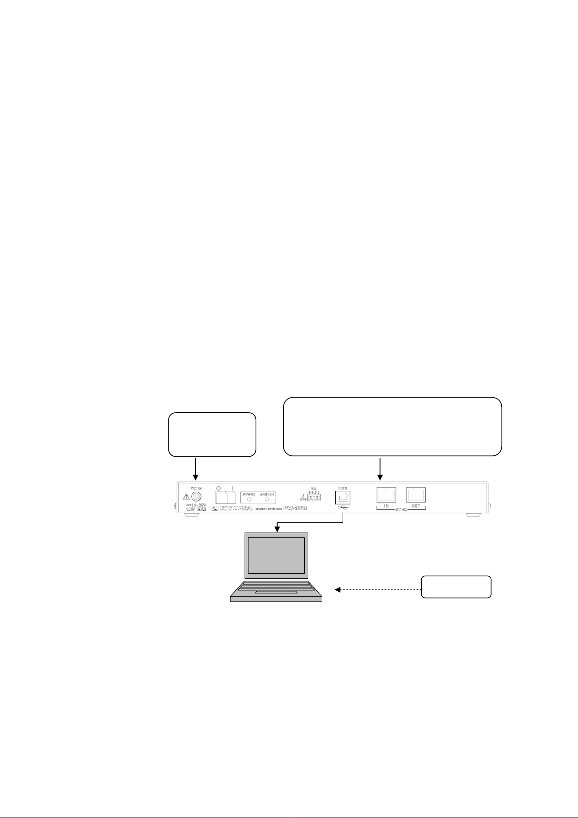
3-7 CONNECTING TO THE PC...............................................................................................................................................22
3-8 POWER ON/OFF.................................................................................................................................................................23
3-9 INSTALLILNG USB DRIVER............................................................................................................................................23
3-10 SELF TEST.........................................................................................................................................................................23
4.TROUBLESHOOTING .......................................................................................................................................... 24
5. TECHNICAL INFORMATION ............................................................................................................................ 25
5-1 USING STRAIN GAGE HAVING GAGE FACTOR OTHER THAN 2.00 .....................................................................25
5-2 USING EXTENSION CABLE.............................................................................................................................................25
5-3 SPECIAL TERMS................................................................................................................................................................26
6. SPECIFICATIONS ................................................................................................................................................ 27
6-1 SPEIFICATIONS .................................................................................................................................................................27
6-2 OUTSIDE DRAWING .........................................................................................................................................................30

1
STANDARD ACCESSORIES
The following accessories are enclosed with the PCD-300B Sensor Interface (hereinafter referred to as
the PCD-300B). After unpacking, check all the required accessories are correctly prepared.
<PCD-300B, PCD-300B-F, PCD-301B, PCD-301B-F>
Dynamic Data Recording Software DCS-100A
Instruction Manual ......................................................... 1 (CD-R)
USB Driver File
USB Cable N-38: 1m ....................................................................................................... 1
AC Adapter UI308-12 ...................................................................................................... 1
Ground Wire P-72 ............................................................................................................ 1
Inspection Report & Warranty ......................................................................................... 1
Analog Output Cable (U-64) (For the PCD-301B and PCD-301B-F only)....................... 1
<PCD-300B-0, PCD-300B-F-0, PCD-301B-0, PCD-301B-F-0>
Simplified Data Recording Software for the PCD
Instruction Manual ..................................................... 1 (CD-R)
USB Driver File
USB Cable N-38: 1m ....................................................................................................... 1
AC Adapter UI318-12 ...................................................................................................... 1
Ground Wire P-72 ............................................................................................................ 1
Inspection Report & Warranty ......................................................................................... 1
Analog Output Cable (U-64) (For the PCD-301B and PCD-301B-F-0 only) ................... 1
OPTIONALS
Input Adapter for Strain Gage Transducer: .................... UI-10A
(NDIS connector, TEDS compatible)
Input Adapter for Strain Gage: ....................................... UI-11A
(Clamp type terminal block connector, TEDS
compatible)
Input Adapter for Strain Gage with Operating Lever: ..... UI-15A
(Clamp terminal block with operating lever,
Not compatible with TEDS)
One-touch Lock Type Input Adapter for Strain Gage: ... UI-16A
(One-touch lock type clamp terminal block,
Not compatible with TEDS)
Connection Cable:............................................................ N-97 (Input terminal ←Cable for connecting
sensors with NDIS connector, 0.1 m)
Synchronous Cable: ......................................................... N-90 (25 cm)
USB Cable: .................................................................... N-39 (2 m)
DC Power Supply Cable For PCD: ................................ P-73 (2 m)
AC Adapter for 4 PCD-300B units: ............................... SA-34A
Data Analysis Software: ................................................. DAS-100A and NI DIAdem

2
SAFETY PRECAUTIONS
PRIOR TO USE
This Manual describes detailed instructions for installing and setting up the PCD-300B. Always operate
the PCD-300B in correct manner for safety.
For safe use of the PCD-300B, do not forget to read the “Safety Precautions” prior to use.
Kyowa Electronic Instruments Co., Ltd. assumes no liability for any damages resulting from user’s
failure to comply with the safety precautions.
SAFETY SYMBOLS
For safety operation of the PCD-300B, the following WARNING and CAUTION symbols are used in
“Safety Precautions” of this Instruction Manual.
WARNING
Improper operation of the system may result in death or severe injury
of the operator.
CAUTION
Improper operation of the system may result in injury of the operator
and physical damage of the system.
WARNING
●Power Supply
To prevent a fire hazard, before connecting the AC adaptor, do not forget to check whether power
supply voltage currently used is conforming to the specifications of the PCD-300B.
●AC Adaptor
To prevent an electric shock or fire hazard, always use the accessory or optional AC adaptor.
●Avoid Using in Environment with Inflammable Gas, etc.
To prevent the risk of fire hazard or explosion, do not use the PCD-300B in environment with
inflammable gas, vapor or dust.
●If Any Trouble Occurs
To prevent a fire hazard, if smoke is emitted from the PCD-300B, immediately disconnect the
AC adaptor from the receptacle and stop using the PCD-300B.
●Avoid Measuring Object Applied With High Voltage
Although the PCD-300B is insulated, if it is used for measuring objects with excessive high
voltage, it may deteriorate its performance and cause trouble.
●Protective Grounding
Do not forget to connect the protective ground terminal. Or, electric shock hazard, deteriorated
performance, and damage of the product may result.
●Maximum Input Voltage Range
The PCD-300B is a measuring instrument specified for strain gage transducers and strain gages.
Do not input high voltage. Or, deteriorated performance and damage of the product may result.

3
CAUTION
●After turning OFF the power switch, wait more than 5 seconds to turn ON the power once again.
If the power is repeatedly turned ON and OFF within 5 seconds, rush current generated by
switching the power ON may blow out the fuse and damage the PCD-300B.
●Use the PCD-300B within temperature ranging from 0 to 40℃.
Use at temperatures exceeding the specified range may lower the performance and cause trouble.
If use under direct sunlight or in a cold place is inevitable, prepare a sunscreen or take proper
measures to keep it warm.
●Use the PCD-300B within relative humidity ranging from 20 to 85% RH.
Use in a humid place exceeding the specified range or where it is exposed to splashing water
may lower the performance and cause trouble.
●Immediately stop the PCD-300B if operating environment changes abruptly.
Leave the PCD-300B as it is until it becomes adaptable to the environment.
Abrupt change in ambient temperature due to transportation, etc. may cause dew condensation
resulting to deteriorate its performance and cause trouble.
●Avoid using PCD-300B in dusty environment
Always use the PCD-300B in environment with no dust and dirt applicable for personal
computers.
●Avoid using PCD-300B in environment affected by vibration or impact.
Always use the PD-300B in environment with no vibration or impact.
If the PCD-300B is continuously affected by vibration or excessive impact, deteriorated
performance or damage of the product may result.
●Avoid using PCD-300B in environment with strong electromagnetic field
Always use the PCD-300B in environment applicable for personal computers.
Do not use the PCD-300B in environment close to apparatuses generating strong electric fields,
for example, radio, microwave oven, electric furnace, etc. Or, deteriorated performance,
malfunction, damage of the product may result.
●Avoid using PCD-300B under poor power supply conditions.
When using the AC adapter : 100 to 240 VAC and 50/60 Hz
When using DC power supply : 11 to 30 VDC
Use power supply with no instantaneous power failure or noise.
●Do not pull connection cables.
Always connect connection cables with a certain play to avoid forced power applying to the
connected portions. Pulling or applying unreasonable force may cause trouble or interrupt the
measurement.
●Take special care when handling the CD-R.
Do not store the CD-R at a place exposing to direct sunlight or with excessively high
temperature or humidity.
Do not put anything on the CD-R or bend or apply stress on it.
Take care not to damage both surfaces of the CD-R with fingerprints, dirt or scratch.
●Preheat the PCD-300B before use.
After the power ON, always preheat the PCD-300B for approximately 30 minutes.

4
NOTATIONS USED IN THE INSTRUCTION MANUAL
NOTATIONS
Names on the panel face is enclosed with parenthesis [ ].
INFORMATIONAL NOTES
Certain notations are used as necessary to attract your attention to information that requires special care
when handing the PCD-300B, and to information provided for reference purposes.
Examples of Notations
Essential precautions required when handling the PCD-300B.
NOTE
Reference items required when handling the PCD-300B.
MEMO

5
1. OUTLINE OF THE PRODUCT
1-1 OUTLINE OF THE PRODUCT
The PCD-300B is a measuring instrument that can be used with no difficulty by connecting to the PC
via USB interface.
By using the accessory Dynamic Data Recording Software DCS-100A (hereinafter referred to as the
DCS-100A), the PCD-300B is capable of measuring strain, stress, force, pressure, acceleration, and
displacement by connecting strain gages and strain gage transducers. In addition, customers can prepare
your own control software.
Features
• Since the PCD-300B is connected to the PC via the USB interface, it can be used by almost all the
PCs.
• Since the PCD-300B has a bridge box built-in, it is capable of conducting 1-gage method experiment
for strain gages solely by itself.
• The PCD-300B is provided with input adapters applicable for the sensors.
• Since the PCD-300B is capable of measurement of 4 channels per PCD-300B and maximum 16
channels with 4 PCD-300B units, the PCD-300B is applicable for measurement in a wide range from a
simple experiment to advanced measurement.
• When using TEDS compatible sensors, by loading sensor information with TEDS function, the
PCD-300B is capable of laborsaving when setting amplifier.
• Data analysis is available with the optional Data Analysis Software (DAS-100A and NI DIAdem).

6
1-2 SYSTEM CONFIGURATION
PC .................................When using the USB interface, always use PC with Windows2000/XP (32-bit
version)/Vista (32-bit version) installed and equipped with USB interface.
In addition, when using the DCS-100A, it is recommended to use the PC with
the following specifications or more.
CPU: Pentium4 2 GHz or more
Memory: 1 GB or more
Display: 1024 × 768 dots or more
USB Cable ...................Accessory
AC Adapter ..................Use accessory AC adapter.
USB Hub ......................When multiple PCD-300B units are used, customers are required to purchase
USB1.1 hub
Note: Use the specified USB1.1 hub.
DCS-100A ....................Install the DCS-100A into the PC. Or customers can prepare your own control
software.
Power supply:
AC adapter
Input (Sensor) 4 CHs: (From rear panel)
Strain gage (120 Ω)
Strain gage transducer (120 to 1 kΩ)
DCS-100A
USB cable
Install
PC:
Windows2000/XP/Vista
Memor
y
: 1 GB

7
2.PARTS NAMES AND PRINCIPAL FUNCTIONS
2-1 FRONT PANEL
1) 2) 3) 4) 5) 6) 7) 8)
1) [DC IN] Connector ......................... Connect the accessory AC adapter.
Power supply voltage range of the PCD-300B is 11 to 30 VDC.
Polarity center is plus (+) and exterior is minus (-). Power
supply voltage range of the AC adapter is from 100 to 240
VAC, 50/60Hz. See “3-1 CONNECTING AC POEWER
SUPPLY” and “3-2 CONNECTING DC POEWER SUPPLY.”
2) Power Supply Switch ...................... Turn this switch to the [○] side to power OFF and, [ | ] side to
power ON.
3) [POWER] Lamp .............................. Lights up with the power ON.
4) [MASTER] Lamp ........................... Lights up when stand-alone type and master PCD-300B are
operating and turns OFF when slave PCD-300Bs are operating.
For details of the slave PCD-300B, see “3-3 SETTING PCD
NO.”
5) [No.] Switch .................................... A switch to set the PCD No. Channel is determined by the PCD
No. Turn up this switch to ON and turn down, to OFF. See
“3-3 SETTING PCD NO.”
Relations between PCD setting, PCD No, and CH No. are
described in the following table.
[No.] Switch
Configuration PCD Setting
State 8 4 2 1
PCD No. CH No.
Stand-alone Stand-alone OFF OFF OFF ON 1 1 to 4
Master OFF OFF OFF ON 1 1 to 4
Slave 1 OFF OFF ON OFF 2 5 to 8
Slave 2 OFF OFF ON ON 3 9 to 12
Synchronous Operation
Slave 3 OFF ON OFF OFF 4 13 to 16
6) [USB] Connector ............................ Connect the accessory USB cable.
7) [SYNC IN] Connector ...................... When using multiple PCD-300B units, connects synchronous
cables N-90 (Optional).
Connected to the master PCD-300B to input signals into the
master PCD-300B.
8) [SYNC OUT] Connector ................ When using multiple PCD-300B units, connects accessory
synchronous cables.
Connected to slave PCD-300B units to output signals to the
slave PCD-300B units.

8
2-2 REAR PANEL
With Input Adapter UI-10A
1) 2) 1) 3)
1) Jackscrew ........................................ Loosen the jackscrews to remove the input adapter. When
mounting the input adapter, fasten the jackscrews. Tightly
fasten the jackscrews with a flathead screwdriver. It is in
common with all input adapters.
2) Input Connector .............................. Connects a strain gage transducer.
3) [GND] Terminal .............................. Protective ground terminal.
4) Analog Output Terminal ................. The analog output cable (U-64) is equipped to the PCD-301B.
Connect the analog output cable to the Analog Output Terminal
and apply an input equivalent to the range. An analog output
±5 V ±0.05 V can be obtained.
With Input Adapter UI-11A
1)
1) Input Terminal Block ...................... Terminal block for connecting strain gages or strain gage
transducers. Use a UI-11A accessory small flathead
screwdriver for connection. When connecting the strain gage
transducers, use optional connection cable N-97.
(PCD-301B/PCD-301B-F only)
4)

9
With Input Adapter UI-15A
2) 1) 2)
1) Input Terminal Block with Operating Lever
Terminal block for connecting strain gages or strain gage
transducers. Push the operating lever for connection. When
connecting the strain gage transducer, use an optional
connection cable N-97. In addition, if a shield wire is attached
to the sensor cable, connect it to item 2) with a screw.
With Input Adapter UI-16A
1)
1) One-touch Lock Type Input Terminal Block
Terminal block for connecting strain gages or strain gage
transducers. Use a UI-16A accessory small flathead
screwdriver for connection. When connecting the strain gage
transducers, use an optional connection cable N-97.

10
3. SYSTEM INSTALLATION
3-1 CONNECTING AC POWER SUPPLY
Use accessory AC adaptor for supplying power to the PCD-300B.
Before connecting the AC adapter to the AC power outlet, check the power supply voltage.
Operating power supply voltage range of the accessory AC adapter is 100 to 240 VAC (50/60 Hz).
If the power supply voltage is outside the above specified range or if the power voltage terminal has
potential with excessive power voltage against the ground, do not connect the AC adapter. Or, it may
cause trouble or damage to the PCD-300B.
Method for checking the power supply voltage is described in the following.
1) Measure voltage between AC power plug terminals with a
tester and check the voltage is 100 to 240 VAC.
2) Measure voltage between the ground and each one end of
the AC power plug with a tester and check one end has 0 V
and the other, 100 to 240 V.
3) If the PCD-300B is used at site using noise generating devices such as induction motors, electric
welding machines, etc., power supply condition may be deteriorated due to the excessive noise. Take
appropriate measures against the noise by using an insulation transformer (Optional: UTP-300B) or
commercially available noise-cut transformers.
Tester Tester
Tester
Ground

11
3-2 CONNECTING DC POWER SUPPLY
Check the power supply voltage before connecting the DC power supply from the exterior side.
Operating power supply voltage range: 11 to 30 VDC
When the power supply voltage exceeds the above voltage range, never connect the PCD-300B. Or, the
PCD-300B may be damaged or cause trouble.
In addition, use the P-73 (Optional) to connect the DC power supply.

12
3-3 SETTING PCD NO.
Set the PCD No. of the PCD-300B with [No.] switch on the front panel.
Relations between [No.] switch, PCD No., and Channel is described in the following table.
[No.] Switch
Configuration PCD Setting
State 8 4 2 1
PCD No. CH No.
Stand-alone Stand-alone OFF OFF OFF ON 1 1 to 4
Master OFF OFF OFF ON 1 1 to 4
Slave 1 OFF OFF ON OFF 2 5 to 8
Slave 2 OFF OFF ON ON 3 9 to 12
Synchronous Operation
Slave 3 OFF ON OFF OFF 4 13 to 16
Stand-alone ............. When using only 1 PCD
Master ..................... 1st PCD (PCD No. 1) when using multiple PCD units for synchronous
operation.
Slave 1 .................... 2nd PCD (PCD No. 2) when using multiple PCD units for synchronous
operation.
Slave 2 .................... 3rd PCD (PCD No. 3) when using multiple PCD units for synchronous
operation.
Slave 3 .................... 4th PCD (PCD No. 4) when using multiple PCD units for synchronous
peration.
MEMO

13
• Before setting the PCD No., turn OFF the power.
• Do not set PCD Nos. other than mentioned in the table in the previous page. Or, proper
operation is not available.
• When setting a PCD No. as a stand-alone or a master PCD, numeric ‘1’ is fixed.
Therefore, turn ON only No. ‘1’ of the [No.] Switch.
• The PCD-300B reads the PCD No. when the power is turned ON.
* When the PCD-300B is mixedly connected with PCD-300A or PCD-320A for synchronous
operation, always set the PCD-300B to a master unit. When multiple PCD-300B units are
connected, set the PCD Nos. of the PCD-300B units to smaller Nos. than those of the
PCD-300A or PCD-320A.
Ex. 1) When combining PCD-300A: 1, PCD-320A: 1, and PCD-300B: 1
Master (PCD No. 1) PCD-300B (* Set the PCD-300B as the master unit.)
Slave 1 (PCD No. 2) PCD-300A (or PCD-320A)
Slave 2 (PCD No. 3) PCD-320A (or PCD-300A)
Ex. 2) When combining PCD-300A: 1, PCD-320A: 1, and PCD-300B: 2
Master (PCD No. 1) PCD-300B (* Set the PCD-300B as the master unit.)
Slave 1 (PCD No. 2) PCD-300B (Set the PCD No. of the PCD-300B to a smaller
number than those of the PCD-300A/320A.)
Slave 2 (PCD No. 3) PCD-300A (or PCD-320A)
Slave (PCD No. 4) PCD-320A (or PCD-300A)
Ex. 3) When combining PCD-300A: 1 and PCD-300B: 3
Master (PCD No. 1) PCD-300B (* Set the PCD-300B as the master unit.)
Slave 1 (PCD No. 2) PCD-300B (Set the PCD No. of the PCD-300B to a smaller
number than that of the PCD-300A.)
Slave 2 (PCD No. 3) PCD-300B (Set the PCD No. of the PCD-300B to a smaller
number than that of the PCD-300A.)
Slave 3 (PCD No. 4) PCD-300A
NOTE

14
3-4 CONNECTING SENSORS.
3-4-1 Input Adapter Types and Features
UI-10A: Input adapter equipped with NDIS one-touch connector used for connecting a
strain gage transducer. It is a TEDS compatible input adapter. For 1-gage/2-gage
method measurement, connect KYOWA’s bridge box (Optional).
UI-11A: Input adapter equipped with clamp type terminal block. Connect with an
accessory screwdriver. In addition, mounting and demounting the terminal block
portion is available. It is a TEDS compatible input adapter.
For 1-gage/2-gage/4-gage connection, see “3-4-2 Input Adapter Connection
Method.”
UI-15A: Input adapter equipped with an operating lever and no tool is necessary for
connection. Press down the operating lever for connecting the lead wire. It is not
compatible with the TEDS.
For 1-gage/2-gage/4-gage connection, see “3-4-2 Input Adapter Connection
Method.”
UI-16A: Input adapter equipped with one-touch lock type terminal block. Press in the lock
button with an accessory tool or fine tool and after inserting the lead wire, pull
back the lock button to the original portion with fingers. It is not compatible with
TEDS.
For 1-gage/2-gage/4-gage connection, see “3-4-2 Input Adapter Connection
Method.”
Press the UI-15A operating lever straight against the lever. While pressing the operating lever,
insert the lead wire. After the lead wire is inserted into the operating lever, do not abruptly
release your fingers from the operating lever. Or, damage of the lead wire and trouble in the
operating lever may result. The operating lever may break due to the above erroneous operation
as well as due to aged deterioration of the product. At this time, contact KYOWA or our
representative for repair.
NOTE
• Operation available range of input adapters
UI-11A Single wire 0.50 to 1.5 mm2, twisted wire 0.13 to 1.4 mm2, 26 to 14 AWG (UL)
UI-15A Single wire 0.08 to 2.5 mm2, twisted wire 0.08 to 1.5 mm2, 28 to 12 AWG (UL)
UI-16A Single wire 0.13 to 1.1 mm2, twisted wire 0.2 to 0.75 mm2, 26 to 16 AWG (UL)
For wires with small wire diameter, twist them by holding twofold or threefold before
connecting the AC adapter.
• When connecting NDIS connector equipped sensors to input adapters UI-11A, UI-15A, and
UI-16A, use optional connection cable N-97.
MEMO

15
3-4-2 Input Adapter Connection Method
When connecting sensors to the PCD-300B, connect the sensors for every input adapter.
Input Adapter Applicable Gage Connection Method Remarks
UI-10A
Specified for 4-gage method
(For strain gage transducer)
Gage resistance
120 to 1000 Ω
A:+BV
B:-SIG
C:-BV
D:+SIG
E: Shield
F:+TEDS
G:-TEDS
TEDS compatible
1-gage method
(3-wire system connection)
Gage resistance
120 Ω
1-gage method
(2-wire system connection)
Gage resistance
120 Ω
2-gage method
Gage resistance
120 Ω
UI-11A
4-gage method
Gage resistance
120 to 1000 Ω
A:+BV
B:-SIG
C:-BV
D:+SIG
E: Shield
F:+TEDS
G:-TEDS
TEDS compatible
For 1-gage method, it is recommended to adopt a 3-wire system connection that has little error
factor affected by temperature difference, balance dislocation, etc. on gage lead wires.
For wiring, use KYOWA’s low-noise lead wire (Model: L-13/14/15/16) with shield and
4-conductor shielded wire. In addition, set them apart from power line wiring and wiring with
excessive interfering noise.
NOTE
If the measurement is unstable, it may be solved by grounding the [GND] terminal on the
PCD-300B rear panel.
MEMO

16
Input Adapter Applicable Gage Method Connection Method Remarks
1-gage method
(3-wire system connection)
Gage resistance
120 Ω
1-gage method
(2-wire system connection)
Gage resistance
120 Ω
2-gage method
Gage resistance
120 Ω
UI-15A
4-gage method
Gage resistance
120 to 1000 Ω
A:+BV
B:-SIG
C:-BV
D:+SIG
: Shield
Not compatible
with TEDS sensor.
1-gage method
(3-wire system connection)
Gage resistance
120 Ω
1-gage method
(2-wire system connection)
Gage resistance
120 Ω
2-gage method
Gage resistance
120 Ω
UI-16A
4-gage method
Gage resistance
120 to 1000 Ω
A:+BV
B:-SIG
C:-BV
D:+SIG
E: Shield
Not compatible
with TEDS sensor.

17
3-4-3 Connection Method
To connect strain gages, etc. with no connectors equipped on the lead wire head, peel off coating from
the lead wire head about 9 to 10 mm in advance and then, connect.
When connecting strain gage transducers, external bridge box, etc. that is equipped with NDIS
connector on the head, the following 2 methods are available.
• Use input adapter UI-10A
• When using input adapters UI-11A, UI-15A, and UI-16A, use a connection cable (Receptacle with
lead wire N-97: Optional) for connection.
When connecting a lead wire to input terminal using input adapters UI-11A and UI-16A, use accessory
small screwdriver.
UI-11A
1) Insert the small screwdriver straight into the square hole of the input terminal. Terminal block
portion of the UI-11A can be mounted or demounted for convenience.
If the small screwdriver is correctly inserted all the way to the end, the screwdriver is left inserted
even if your hand is released. In this state, the clamp in the square hole is opened.
2) With the screwdriver inserted into the square hole, insert a lead wire with its coating peeled off
about 10 mm into the input terminal square hole.
3) While holding the lead wire, extract the screwdriver from the square hole.
Approx. 9 to 10mm
Wire rod

18
4) Gently pull the lead wire to check if it is securely inserted.
UI-16A
1) Push the button of the input terminal until it is locked with the accessory screwdriver.
If it is securely pushed, the button is locked and maintained.
2) Insert the lead wire with its coating peeled off about 10 mm into the round hole all the way to its end
of the input terminal.
3) While holding the lead wire, set back the button to the original position with your finger.
4) Gently pull the lead wire to check if it is securely inserted.
For connection, always use the accessory small screwdriver or a screwdriver of the same size.
When inserting or extracting the screwdriver, do not move it up and down more than required.
Or, it may cause damage to the UI-11A.
NOTE
A
pprox. 9 to 10 mm
Wire rod
For connection, always use the accessory small screwdriver or a screwdriver with a fine head.
NOTE
Table of contents
Other KYOWA Recording Equipment manuals