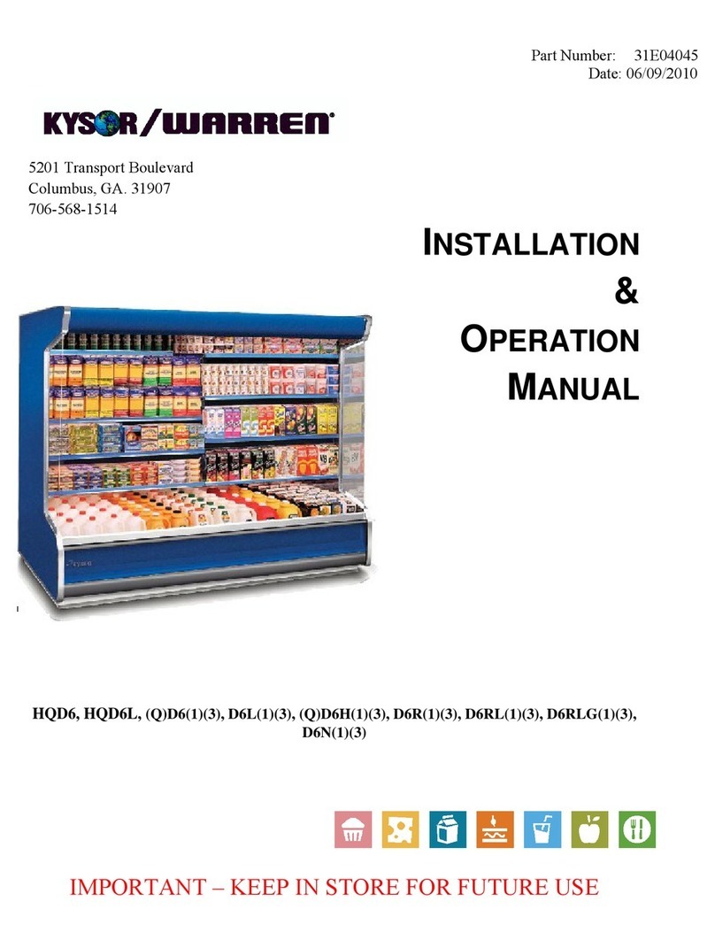
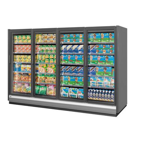
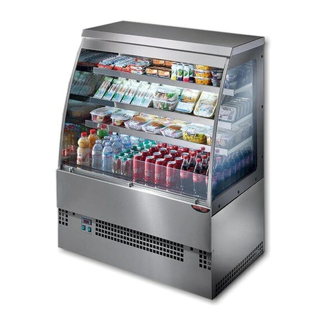
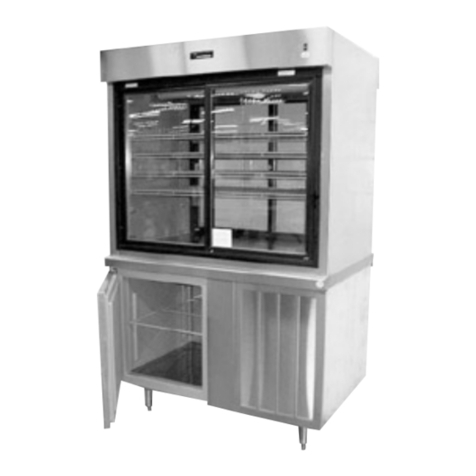
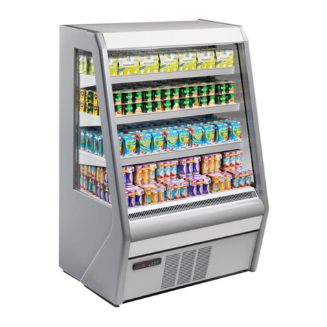
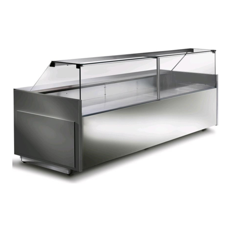
Kysor/Warren DX6LN-MCU User manual

STRATUS Multi-Deck
Display Case
Installation and Operation Manual
KW-IOM-1037 | Version 02
January 2019
Part No. 31E01037
Models:
DX6LN-MCU
Applications:
Introduction—General Information 2
Plan and Cross Section Views 3
Paragon ERC-2 Set-Up Instructions 4
Case Data 7
Case Installation 8
Modular Condensing Unit 11
Electrical Connections—General 17
ECM Evaporator Fan 22
Operation 24
Parts List 26
Warranty 26

Installation and Operation Manual
2
Introduction—General Information
This manual has been prepared for our customers and the personnel involved in installing and maintaining our cases.
Our STRATUS case line has been designed with a focus on things most important to your bottom line. Enhanced
merchandise visibility, high energy efciency, and merchandising exibility have all merged in an attractive design.
Custom styles t seamlessly into your oor plan and an eco-friendly design protects the environment while saving
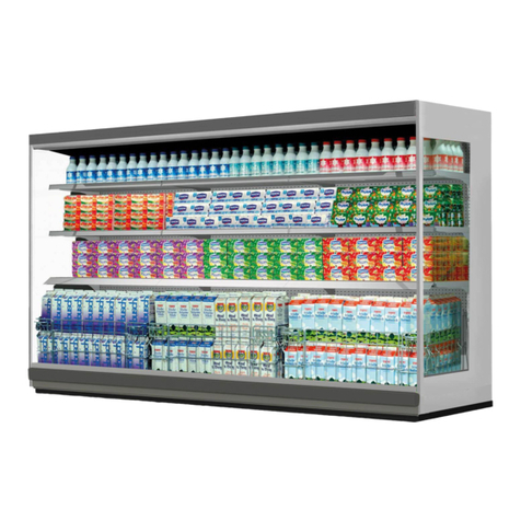
energy costs. The DX6LN multi-deck, dairy door case is available for medium temperature applications.
These cases should be installed and operated according to the instructions contained in this manual to ensure
proper performance. They are designed for display of products in an air conditioned store where temperature and
humidity are maintained at conditions that are below 75°F dry-bulb temperature with 55% relative humidity.
CAUTION: Failure to maintain store air conditions below 75°F dry-bulb temperature with 55% relative humidity may
result in operational issues such as the following: increased thermal (Btuh) load, high product temperatures, coil
icing, product frosting, and external sweating.
This case will accommodate up to 5 levels of product display shelving in addition to the deck pan level for greater
merchandising visibility that grabs shoppers’ attention. These cases offer exceptional display facing area and prod-
uct pack-out in a case that is 97” in height.
Case Description
Model Description
DX6LN-MCU Multi-deck, standard depth, 6 deck, low front, with modular condensing unit
Receiving/Shipping Damage/Lost Items
All equipment should be examined for shipping damage before and during unloading. If there is any damage, the
carrier should be notied immediately and an inspection requested. The delivery receipt must be noted that the
equipment was received damaged. If damage is of a concealed nature, you must contact the carrier within three (3)
days following delivery. The consignee for all damages must le a claim with the carrier.
NOTE: All claims for shortages must be within 10 days after receipt of shipment.
Refrigerant
The DX6LN medium temperature cases use R-448A refrigerant.
NOTE: Refer to Case Data Control Settings for refrigeration requirements.

STRATUS Multi-Deck Display Case
3
Cross Section View
Plan View
80
22
20
161
4
55
6
42
59
11
2
807
8
AIR SPACE
3
42
35
29
293
423
4
161
2
DX6LN - MCU
22
22
22
22
32
353
8
447
8
221
4
1031
8
273
4

Installation and Operation Manual
4
Modular Condensing Unit
The selected condensing unit will have the following features:
• Electrical Rating — 208 – 230V / 60Hz / 1 Phase
• Refrigerant — R-448A
• Receiver and suction service valves
• All refrigerant piping employs sweat connections
• Each condensing unit is designed to operate one case
• Condensing units are UL Listed
Condensate Pump
The condensate pump is a compact suction head type pump. It has the following features:
• Electrical rating - 115 VAC / 60 Hz / 1 Phase, 1.9 Amps
• Capacity: 1.6 GPM at zero head
• Pump is UL Listed
Paragon ERC-2 Controller Set-Up Instructions
A Paragon ERC-2 Controller is provided to control the compressor, fans and case defrost.
• Temperature Control—When the case reaches the desired discharge air temperature, the controller shuts
off the compressor. When the discharge air temperature rises above the cut-in set point, the compressor
turns on.
• Compressor Control—Compressor operating parameters such as minimum off time, minimum run time and
start-up time delay are eld adjustable. Recommended settings are listed in the table on Page 6.
Remote Display
ERC 2—Electronic Refrigeration Control

STRATUS Multi-Deck Display Case
5
The ERC-2 (Electronic Refrigeration Control) is a microprocessor-based electronic controller designed to control
both the temperature and the defrost functions of a commercial refrigeration unit. It can be powered by 120, 208, or
240 VAC (50 or 60 Hz). The control comes with four relay outputs, which are for the following: compressor control,
defrost control, evaporator fan, and alarm.
The ERC-2 includes a digital display module that provides a readout of the temperature, time, and built-in diagnostics.
The display module can be mounted locally or remotely from the unit and contains a touch keypad for programming.
For defrost control it uses a real time clock.
This control is NSF certied and can be applied to many different commercial refrigeration applications like reach-ins,
walk-ins, refrigerated cases, or other different products where accurate control of refrigerated space and defrost cycles
is required.
Programming Paragon Case Controller
Remove cover from Paragon display so display LED is visible as shown.
To change time of day and setpoint temperature (First Level), follow these steps:
1. Press and hold SET for ve (5) seconds. The display will show “CLoC.”
2. Press SET again to change the time of day.
3. Press UP or DOWN until the correct time of day is displayed.
4. Press SET to accept the new time.
5. Press DOWN to go to the next parameter -- Setpoint Temperature. The display will show “SEt.”
6. Press SET to change the setpoint temperature.
7. Press UP or DOWN to go to the desired setpoint. The range is -40 to 60°F or -40 to 16°C.
8. Press SET to accept the change.
9. Press DOWN to exit the rst level of programming.
NOTE: During programming, if no button is pressed for thirty (30) seconds, the control will go back to the normal
operation mode. This is valid for both programming levels.
NOTE: When changing the time, press and hold the MAN DEF button for three (3) seconds to change the AM / PM mode.
To change the other parameters (Second Level), follow these steps:
1. Press and hold SET and DOWN for ten (10) seconds. The display will show “dSPL.” Press SET to change
the parameter.
2. Press UP or DOWN to change options, time, or temperature for the currently selected parameter. Press
SET to accept new value.
3. Press DOWN to go the next parameter. Then, go back to Step 2. After the last parameter is displayed
(ALHi), the display will return to the normal operating condition.

Installation and Operation Manual
6
DX6LN PARAGON ERC-2 Controller Settings
Set the Paragon ERC-2 controller parameters as described in table below:
CloC = Set to local time SEt = 32 dSPL = rSP° CLHr = 12HR
°dSP = F° dFtP = ELEC EFAN = yES CFAN = on
dFin = TdAy CoFF = 0:00 Con = 0:00 Alrd = 0:00
CPrn = NA nodF = 6
dEF1 = 00:00
dEF2 = 04:00
dEF3 = 08:00
dEF4 = 12:00
dEF5 = 16:00
dEF6 = 20:00
dEFd = 25
Fand = 0:00 Pudn = 0:00 DriP = 0:00 diF° = 1
tDEF = NA dEF° = 47° Fan = NA ALLo = 27
ALHi = 60
Condensate Evaporation Pan Heater
The Condensate Evaporation Pan Heater has the following features:
• Electrical Rating: 208V / 60Hz / 1 Phase, 6 ft case: 7.21A, 1500 W, 8 ft case: 14.42A, 3000W
12 ft case: 14.42A, 3000W
• Condensate Dissipation Rate: 6 ft case: 9.3 gallons per day, 8 ft case: 18.5 gallons per day
12ft case: 18.5 gallons per day
• 3.75 Gallon Pan: (A) 6 ft: 1 pan, (B) 8 ft: 2 pans, (C) 12 ft: 2 pans
• Evaporation pan heater is UL Listed.
Buck and Boost Transformer (Optional)
A 1.5 KVA Buck & Boost transformer is an available option. The primary and secondary of the Buck & Boost trans-
former can be interconnected for use as an autotransformer to slightly step up or down voltages. When used as an
autotransformer to slightly adjust voltage, the Buck & Boost Transformer can carry loads in excess of its nameplate
rating.
Example: With the transformer wired to provide 208V output with 195V input, the load capacity of the transformer is
19.5 KVA.
When the Buck & Boost transformer option is chosen, the transformer is factory wired to provide 208V output with
195V input. The transformer connections can be rewired in the eld to provide alternative buck and boost percent-
ages. Wiring instructions are provided on the transformer cover. Transformer is UL listed.

STRATUS Multi-Deck Display Case
7
The fail safe time may be extended to a maximum of 28 minutes to allow for store condition variations,
refrigeration system variations, and heavy shopping trafc. If the fail safe time is extended, the termina-
tion temperature must remain at 47°F.
ISSUE DATE: JANUARY 2019
DX6LN-MCU
SINGLE DECK MERCHANDISER
APPLICATIONS
General Case Data 6’ 8’ 12’
Total Display Area (ft2)28.10 37.40 56.20
Cubic Capacity (ft3)71.60 96.50 143.20
Max Shelf Depth (in) [Top/Bottom] 22/22 22/22 22/22
Weight (lb) ---
Ther mal Load (General )
Evaporator Temperature (˚F) 22 22 22
Discharge Air Temp (˚F) 35 35 35
Discharge Air Velocity (fpm) 200-300 200-300 200-300
Fan Speed (rpm) 2200 2200 2200
Refrigerant Type R-448A R-448A R-448A
Estimated Refrigerant Charge (lbs) 8.00 10.00 14.00
Conventional Thermal Load, Single (Btuh) unlighted 8007 10676 16014
Superheat Setpoint (˚F) 6 - 8 6 - 8 6 - 8
Electrical Data (Amps/Watts)
208V/60HZ/1PH 208V/60HZ/1PH 208V/60HZ/1PH
115V/60HZ/1PH 115V/60HZ/1PH 115V/60HZ/1PH
Evaporator Fan Motor Amps (115 V) 0.60 0.60 0.90
Anti-sweat Heater Amps (115 V) N / A N / A N / A
Lights Amps (115V) 0.43 0.47 0.71
Defrost Heater Amps N / A N / A N / A
Condensate Pump Amps (115 V) 1.90 1.90 1.90
Compressor RLA (208 V) 12.00 15.70 23.20
Condenser Fan Motor Amps (208 V) 2.20 2.20 2.20
Refrigeration Cycle Amps 2.03 2.12 2.69
Defrost Cycle Amps 2.03 2.12 2.69
Evaporation Pan(s) Heater Amps (208 V) 7.21 14.42 14.42
Case Circuit Minimum Circuit Ampacity (Circuit 1) 2.54 2.65 3.36
Case Circuit Maximum Overcurrent Protection (Circuit 1) 15 15 15
Condensing Circuit Unit Minimum Circuit Ampacity (Circuit 2) 17.20 21.83 31.20
Condensing Circuit Unit Max. Overcurrent Protection (Circuit 2) 25 35 50
Evaporation Pan(s) Circuit Minimum Circuit Ampacity (Circuit 3) 9.01 18.03 18.03
Evaporation Pan(s) Circuit Max. Overcurrent Protection (Circuit 3)
15 20 20
1 At ASHRAE conditions. For conditions above 75°F, 55% RH, increase
defr ost tim e by 15 min. Type I refrigerator , intended for use in an area where
the environm ental conditions are controlled and maintained that conditions do
not exceed 75°F and 55% relative hum idity. Kysor W ar ren, whose policy is
one of continuous improvement, reserves the right to change at any tim e
specifications, designs, or prices without incur ring obligation. DOE 2017
Compliant
Case Length (ft)
Power Supply (Volts/Hertz/Phase)
Defrosts per Day
Failsafe Duration (min)
1
Termination Temp (˚F) Drip Time (min)
625 47 0
Defrost Data (IOff Cycle)
Case Data

Installation and Operation Manual
8
Maximum Top Shelving Size Recommended: 22”
NOTE: The refrigerated air curtain is very important to the performance of this case. The load limit line (see operation
section) is the indicator of the inside edge of the air curtain and at no time should shelving, product, signs, debris,
etc., interfere with the air curtain.
NOTE: Temperature is measured in discharge air. Defrost frequency is at design conditions. Higher temperature or
humidity may require more defrosts per day and longer fail-safe times. These cases are not designed to operate in
environments where the ambient temperature does not exceed 75°F dry bulb temperature with 55% relative humidity.
NOTE: Off-cycle defrost is the recommended defrost type. Refer to www.kysorwarren.com for other electrical data
and information.
CAUTION: Failure to maintain store air conditions below 75°F dry bulb temperature with 55% relative humidity may
result in operational issues such as the following: increased thermal (Btuh) load, high product temperatures, coil
icing, product frosting, and external surface condensation.
CAUTION: Failure to properly install electrical wiring and control wiring per wiring diagrams, defrost settings, and
temperature set-points may result in operational issues such as: increased thermal (Btuh) load, high product tem-
peratures, coil icing, product frosting, and external surface condensation.
Case Installation
These display cases are installed individually.
Preparation—Prepare the installation area as follows:
1. Clean area where case is to be installed.
2. Verify installation area is at least 15 feet from any outside entrances or heating and cooling outlets.
3. Verify at least 2 feet of distance between hot and cold cases.
4. Ensure oor loading will support the case and the case contents.
5. Ensure proper AC power is available. Refer to case AC input requirements located in the electrical connec-
tions section of this manual.
6. Ensure location will allow connection to drain lines and the drain line, when installed, will meet the recom-
mendations as set forth in the refrigeration piping and dehydration section of this manual.
7. Ensure expansion valve in case is the proper valve for the type of refrigerant used at the installation site.
CAUTION: To prevent condensation on the end panels of cases, a minimum of 3.0 inches between walls or other
cases is required for airow. If 3.0 inches is not possible, then the space between the cases must be completely
lled and sealed or an updraft fan kit must be installed to provide air circulation through the space.
Installation
The following instructions are provided for unpacking, moving, loading, and lifting the case prior to installation.
NOTE: READ ALL INSTRUCTIONS CAREFULLY BEFORE BEGINNING INSTALLATION.
Unpacking
WARNING! Use caution when removing the strapping in the following procedure because the shelves are very
heavy and could fall causing personal injury or equipment damage.
1. Remove all shipping tape from lamps and ensure that all lamp ends are snapped rmly in place.
2. Ensure the evaporator cover is installed correctly with the deck pans installed.
3. Move the case into position, install, adjust superheat, and perform the operational checkout procedures
following the instructions within this manual.
CAUTION: Be careful not to damage the factory installed ends while moving the case. Use the case lift points on the
case to move it to the proper location.
STRATUS Multi-Deck Display Case
9
Installing Case
1. Ensure all preparation for installation, as outlined in the above paragraphs, have been fully complied with
and are complete.
2. If multiple cases are to be installed, nd the highest area of the oor to place the rst case.
3. All cases must be located on a rmly based oor and be leveled within plus or minus 1/16 inch.
4. Use metal shims where required to support entire length of the cases at each base leg (front and back). All
base legs must be shimmed under the skid rail where the base leg meets the lower rails (typically every 4’
on 4’ and 8’ cases, and every 6’ on 6’ and 12’ cases). If the case is equipped with adjustable leveling legs,
all legs should be adjusted so that all are making equal contact with the oor for equal weight distribution.
WARNING! If any part of the case rail or leveling leg is not supported at each base leg, the case can ap-
pear out of level or become damaged when product weight is added.
5. If multiple cases are to be installed, refer to the oor plan and install the rst case in the lineup by snapping
a chalk line where the front and rear of the cases are to be located.
6. Continue the chalk line if multiple cases are to be installed. The rst case is typically the case that is at the
highest area on the oor.
7. Connect water drain line. Reference waste outlet (drip pipe) description and location procedure later in this
manual.
8. Connect input AC power. Reference electrical installation procedure later in this manual.
9. Connect refrigerant lines. Reference procedure later in this manual.
10. Install all ends, caps, and trim per the applicable instructions contained in this manual.
11. Remove shipping tape on uorescent lamps and remove all other shipping material.
12. Refer to the operational start up procedures later in this manual. If multiple cases are to be installed, refer
to the following paragraph for installing subsequent cases.
CASE MUST BE LEVELED FROM FRONT TO BACK AND END-TO-END AND SUPPORTED CONTINUOUSLY AS
NEEDED WITH SHIMS UNDER EACH BASE LEG
Shelf standards on back
wall should be aligned
when leveled properly.

Installation and Operation Manual
10
Waste Outlet (Drip Pipe) Description and Location
These cases are equipped with a 1-1/2” PVC waste outlet connection that terminates in the center of the display case
below the insulated bottom. The water seal trap, elbow and cap are shipped loose for eld installation.
NOTE: Improperly installed drain piping can seriously affect the operation of the case and result in increased main-
tenance cost and operation issues. Listed below are some general rules for drain piping installation.
• Never use a double water seal.
• Never use a pipe size smaller than the pipe size or water seal size supplied with the case.
• Always provide as much downslope as possible in drain piping. (1” fall for each 4’ of horizontal run)
• Avoid long runs in drain piping which make it impossible to provide maximum downslope in piping.
• Provide a space between the end of the drip pipe and the oor drain or sewer connection.
Case Freezing
Do not allow drain piping to come into contact with uninsulated suction lines that will cause drain water inside the
drain piping to freeze.
Drain Strainer
NOTE: Not all Kysor Warren cases have drain strainers. Drain strainers are optional. This information applies only to
cases equipped with drain strainers. The drain strainer is used to keep debris or foreign objects from entering the PVC
drain, which could cause blockage. To install, insert into the drain until the drain strainer stops. It will not be ush with
the top of the drain bushing. The strainer will extend above the hub by 1”. DO NOT atten the drain strainer.

STRATUS Multi-Deck Display Case
11
Modular Condensing Unit
Mounting Base and Enclosure
The control box and Buck & Boost transformer are attached to the top of the case. The condensing unit, defrost water
evaporation pan and valance panels are shipped loose and are eld installed. (Refer to pictures)
Assembly—Modular Condensing Unit
The top front valence panel has a rectangular knock out provided for the controller display to be inserted into. The top
valence panel must face the front of the case. The controller display rectangular knockout will be located at the bottom
left front corner of the valence panel.
1. All the components must be installed in the locations as shown in the photo.
2. The condensing unit must be positioned on top of the case in the position so that the condenser coil fac-
es the right end of the case when viewed from the front of the case. The condensing unit must be aligned
so that the refrigeration piping quick connect couplings can be attached to the condensing unit The con-
densing unit should be screwed down to the top of the case after connecting the refrigeration piping quick
connect couplings.
3. When the condensing unit is installed properly, there must be a minimum air gap of 12” or more between
the air inlet side of the condenser coil and the end valance panel. A minimum space of 5” or more must be
provided between the rear of the condensing unit and the rear valance panel.
4. All electrical wires must be routed inside exible metallic conduit.
Refrigeration Piping Connections
This case is designed to operate with a 208-230 Volt single condensing unit located on top of the case. Condensing
units are supplied with refrigeration line quick connect couplings. (See installation of quick connect refrigeration line
coupling for reference).

Installation and Operation Manual
12
Assembly—Condensate Pump
The DX6LN case has approximately 9.92 lb condensate/ft/day. Special care is required to ensure the condensate can
be evaporated or drained to the sewer. It can save a lot of energy by draining the condensate to the sewer. If there is no
access for drainage, please install the drain-evaporator mechanism in the following way to prevent the water overow
to the oor. Please follow the instructions for correct installation:
1. Mount the condensate evaporation pan(s) on the top of the case.
2. Assemble the condensate plumbing as shown below.

STRATUS Multi-Deck Display Case
13
Assembly—Condensate Pump (cont.)
3. Condensate is collected into the condensate pump with the following diagram.
4. Please ensure that the condensate ows into the pump pan. Ensure there is no leakage at the joints.

Installation and Operation Manual
14
Refrigeration Piping Coupling Connection Instructions
The couplings on the ends of the pre-charged line sets are self-sealing when installed properly. Follow these instruc-
tions carefully. An EPA Certied Type II or higher technician must perform these steps.
Initial Connections
1. Remove the protector caps and plugs. Wipe the seats and threaded surfaces with a clean cloth to remove
any possible foreign matter.
2. Thoroughly lubricate the threads, O-rings, diaphragms, and all internal coupling surfaces with polyol ester
(POE) refrigerant oil.
CAUTION: Lubricating is very important. Couplings will leak without lubrication.
Swivel Nut Before Connecting Male End Before Connecting Clean and Lubricate Couplings
3. Position the condenser with the ttings facing the female ttings on the case. See picture above for loca-
tions and tting size in table below.
4. Begin to tighten the couplings together by hand. Continue to turn the swivel nuts by hand until it is certain
that the threads are properly engaged.
5. Using two wrenches, one to rotate the swivel nut and one to hold the male tting in place, tighten each
coupling.
CAUTION: It is CRITICAL that ONLY the NUT on the pre-charged tube be turned, or the diaphragms will be torn by
the piercing knives and become loose in the refrigeration system causing severe operational problems.
NOTE: As the coupling is tightened, the diaphragms in the quick connect couplings will begin to be pierced. As that
happens, there will be increased resistance to tightening the swivel nut.
6. Continue tightening the swivel nut until it bottoms out or a very denite
increase in resistance is felt (no threads should be showing). DO NOT
OVER-TIGHTEN.
7. Use a marker or pen to mark a line on the coupling nut and unit panel.
Then tighten the coupling nut an additional one-quarter turn.
8. After all connections have been made, check the couplings for leaks.
Tighten Swivel Nut

STRATUS Multi-Deck Display Case
15
Coupling Description
The following pages show the stages of coupling assembly as the swivel nut
and male tting are drawn together.
The swivel nut end contains one diaphragm in the center post. The male
tting contains the knife blades and its own diaphragm.
NOTE: 3/8 male ends have one knife blade.
No sealing takes place until the nal stage, when the outer edge of the
center post in the swivel nut is forced against the bottom of the male tting,
creating a mechanical seal.
Below appears to be a completed assembly with only two threads showing, but the diaphragms have just begun to
be pierced. This causes severe operational issues as well as refrigerant leaks.
Two Threads Showing Knives Just Showing Barely Pierced
Below shows an even more complete assembly, with only one thread showing. However, this assembly is still not
complete. If not tightened further, there will be refrigeration restrictions and leaks.
One Thread Showing Knives Exposed Partly Pierced
Rotate Swivel Nut 1/4 Turn More

Installation and Operation Manual
16
Below shows the two parts almost together; the threads are ush. At this point the main problem will be refrigerant leaks.
Threads Flush Knives Visible Pierced, but will leak
Correctly Tightened Knives Fully Open Fully Pierced
NOTE: Couplings that are screwed together but have threads showing are not only leaking refrigerant, they are re-
stricting the ow of refrigerant through the small slits in the membranes or diaphragms.
NOTE: The condensate drain pan will slide under the case. The pump will be located under the case. An outlet is
provided under the case to plug the pump into. Under no conditions should anything else be plugged into this outlet.
A 3/8" plastic drain tube is supplied with the case and must run from the drain pan pump up the back of the case to
the top of the case and into the evaporative condensate pan.
The copper loop on the end of the tube hangs over the edge of the evaporative pan.

STRATUS Multi-Deck Display Case
17
Electrical Connections—General
WARNING! Ensure the kickplate does not come in contact with the case electrical wiring. Live electrical wiring that
comes in contact with the case is a shock hazard that may cause severe injury or death by electrocution.
WARNING! Always disconnect the electrical power at the main disconnect when servicing or replacing any electrical
component. This includes, but is not limited to items such as fans, heaters, thermostats, and light bulbs. Failure to
disconnect the electrical power may result in personal injury or death.
CAUTION: Failure to properly install electrical wiring and control wiring as per wiring diagram(s), defrost settings,
and temperature set-points may result in operational issues such as the following: increased thermal load, high prod-
uct temperature, coil icing, product frosting, and external sweating.
Shelf Light Installation—T8 Shelf Lights
• Make sure plugs are FULLY SEATED before applying power.
• Due to the nature of rapid start ballasts, it is highly recommended that lights are plugged in BEFORE power
is applied to cases, and BEFORE cases are at a steady rate operating temperature.
• If lights icker when rst started up, disconnect power to lights, verify plug is fully seated, and then ensure
power is off for at least 20 seconds before re-applying power.
CAUTION: Failure to follow these instructions may result in premature bulb and ballast failure.
NOTE: Failure to follow installation instructions may void standard warranty.
Electrical Termination
There are three eld power supply connections consisting of: (A) case power supply; (B) condensing unit power
supply (C) defrost water evaporation pan power supply. (see Wiring Diagrams in this section)

Installation and Operation Manual
18
Wiring Diagram / 6 Ft. Model
P14
P12
P10
P9
P11
ERC-2
CASE
CONTROLLER
DISCHARGE
AIR SENSOR
P7
P8
P2
P1
P1A
H1
H3
H2
H4
DISC AIR
SENSOR
COIL
SENSOR
REMOTE
DISPLAY
DEFROST
TERMINATION
SENSOR BLK
BLK
BLK
BLK
NL1
M
115V FAN MOTOR(S)
115V
LIGHTS
TERMINAL BOARD
(10H12048)
CONDENSATE
PUMP GFCI OUTLET
BLK
BLK
BLK
BLK
3 - BLK RIB
3 - BLK RIB
4 - BLK
5 - WHT
4 - BLK
6 - BLK
CONDENSING UNIT
CIRCUIT 1
CASE POWER SUPPLY
115 VAC, 50/60 Hz
SINGLE PHASE
10
AWG
BLK
BLK
BLK
BLK
WHT
WHT
RELAY
6
87
1
0
342
115V VAC
BLK
BLU
RED
BLK
RED
RED
RED
YEL
BLU
RELAY
STARTING
CAPACITOR
RUNNING
CAPACITOR
RED
BLK
YEL
HARNESS
ELECTRONIC UNIT
CONTROLLER
13 4
9 10
5
11 12
YEL
YEL
FAN-1
R
C
S
DLT
(WHEN REQ'D)
FIXED HP (WHEN REQ'D)
TO SUCTION
TRANSDUCER
YEL
SOLENOID COIL
(WHEN REQUIRED)
CONNECT TO MATCHING
CONTROL CIRCUIT VOLTAGE
BLK
RED
BLK
BLK
RED
BLK
T1 T2
L1 L2
RED
BLU
FAN-2
(WHEN REQ'D) LOAD SIDE OF
CONTACTOR
T2
T1
T2
T1
BLK
BLK
SPLICE
(WHEN REQ'D)
WHT
BLK
BLK
WHT
(BOTTOM)
15A
CIRCUIT
BREAKER
(TOP)
GRN
WHT
BLK
Max
16A
5(1)A
678
2
8(3)A250V~
16FLA/96LRA
14 AWG BLK
CIRCUIT 3
CONDENSATE
EVAPORATION
PAN POWER SUPPLY
208 VAC, 50/60 Hz
SINGLE PHASE
14 AWG WHT
14 AWG GRN
14 AWG BLK
(BOTTOM)
35A
CIRCUIT
BREAKER
(TOP)
10 AWG GRN
10 AWG RED
10 AWG RED
CIRCUIT 2
CONDENSING UNIT (MCU)
POWER SUPPLY
208/230 VAC, 50/60 Hz
SINGLE PHASE
10 AWG RED
S
SOLENOID VALVE
115VAC, 60/50 Hz
BLK
21 - WHT 22 - BLK
21 - WHT
BLK
WHT
YEL
YEL
YEL
YEL
WHT
10 AWG RED
10 AWG RED
10 AWG RED
10 AWG RED
10 AWG RED
10 AWG RED
GND
14 AWG WHT
14AWG
BLK
GRN
GRN
WHT
22 - BLK
YEL
YEL
BLK
13 14 15 16 17
10 AWG RED
WHT BLK
GRN
GRN
GRN
GRN
10 AWG GRN
10 AWG GRN
10 AWG GRN
WHT
14 AWG GRN
6 - BLK
5 - WHT
CONDENSATE
EVAPORATION PAN
208 VAC HEATER
GND
BLK
GRN
WHT14 AWG
14 AWG
14 AWG
14 AWG WHT
(BOTTOM)
15A
CIRCUIT
BREAKER
(TOP)

STRATUS Multi-Deck Display Case
19
Wiring Diagram / 8 Ft. Model
P14
P12
P10
P9
P11
ERC-2
CASE
CONTROLLER
DISCHARGE
AIR SENSOR
P7
P8
P2
P1
P1A
H1
H3
H2
H4
DISC AIR
SENSOR
COIL
SENSOR
REMOTE
DISPLAY
DEFROST
TERMINATION
SENSOR BLK
BLK
BLK
BLK
NL1
M
115V FAN MOTOR(S)
115V
LIGHTS
TERMINAL BOARD
(10H12048)
CONDENSATE
PUMP GFCI OUTLET
BLK
BLK
BLK
BLK
3 - BLK RIB
3 - BLK RIB
4 - BLK
5 - WHT
4 - BLK
6 - BLK
CONDENSING UNIT
CIRCUIT 1
CASE POWER SUPPLY
115 VAC, 50/60 Hz
SINGLE PHASE
10
AWG
BLK
BLK
BLK
BLK
WHT
WHT
RELAY
6
8
7
1
0
342
115V VAC
BLK
BLU
RED
BLK
RED
RED
RED
YEL
BLU
RELAY
STARTING
CAPACITOR
RUNNING
CAPACITOR
RED
BLK
YEL
HARNESS
ELECTRONIC UNIT
CONTROLLER
134
9 10
5
11 12
YEL
YEL
FAN-1
R
C
S
DLT
(WHEN REQ'D)
FIXED HP (WHEN REQ'D)
TO SUCTION
TRANSDUCER
YEL
SOLENOID COIL
(WHEN REQUIRED)
CONNECT TO MATCHING
CONTROL CIRCUIT VOLTAGE
BLK
RED
BLK
BLK
RED
BLK
T1 T2
L1 L2
RED
BLU
FAN-2
(WHEN REQ'D) LOAD SIDE OF
CONTACTOR
T2
T1
T2
T1
BLK
BLK
SPLICE
(WHEN REQ'D)
WHT
BLK
BLK
WHT
(BOTTOM)
15A
CIRCUIT
BREAKER
(TOP)
GRN
WHT
BLK
Max
16A
5(1)A
678
2
8(3)A250V~
16FLA/96LRA
14 AWG BLK
CIRCUIT 3
CONDENSATE
EVAPORATION
PAN POWER SUPPLY
208 VAC, 50/60 Hz
SINGLE PHASE
14 AWG WHT
14 AWG GRN
14 AWG BLK
(BOTTOM)
35A
CIRCUIT
BREAKER
(TOP)
10 AWG GRN
10 AWG RED
10 AWG RED
CIRCUIT 2
CONDENSING UNIT (MCU)
POWER SUPPLY
208/230 VAC, 50/60 Hz
SINGLE PHASE
10 AWG RED
S
SOLENOID VALVE
115VAC, 60/50 Hz
BLK
21 - WHT 22 - BLK
21 - WHT
BLK
WHT
YEL
YEL
YEL
YEL
WHT
10 AWG RED
10 AWG RED
10 AWG RED
10 AWG RED
10 AWG RED
10 AWG RED
GND
14 AWG WHT
14AWG
BLK
GRN
GRN
WHT
22 - BLK
YEL
YEL
BLK
13 14 15 16 17
10 AWG RED
WHT BLK
GRN
GRN
GRN
GRN
10 AWG GRN
10 AWG GRN
10 AWG GRN
WHT
14 AWG GRN
6 - BLK
5 - WHT
CONDENSATE
EVAPORATION PAN 2
208 VAC HEATER
GND
BLK
GRN
WHT
14 AWG
14 AWG
14 AWG
CONDENSATE
EVAPORATION PAN 1
208 VAC HEATER
GND
BLK
GRN
WHT14 AWG
14 AWG
14 AWG
14 AWG WHT
(BOTTOM)
20A
CIRCUIT
BREAKER
(TOP)

Installation and Operation Manual
20
P14
P12
P10
P9
P11
ERC-2
CASE
CONTROLLER
DISCHARGE
AIR SENSOR
P7
P8
P2
P1
P1A
H1
H3
H2
H4
DISC AIR
SENSOR
COIL
SENSOR
REMOTE
DISPLAY
DEFROST
TERMINATION
SENSOR BLK
BLK
BLK
BLK
NL1
M
115V FAN MOTOR(S)
115V
LIGHTS
TERMINAL BOARD
(10H12048)
CONDENSATE
PUMP GFCI OUTLET
BLK
BLK
BLK
BLK
3 - BLK RIB
3 - BLK RIB
4 - BLK
6 - BLK
5 - WHT
5 - WHT
4 - BLK
6 - BLK
CONDENSING UNIT
CIRCUIT 1
CASE POWER SUPPLY
115 VAC, 50/60 Hz
SINGLE PHASE
10
AWG
BLK
BLK
BLK
BLK
WHT
RELAY
6
8
7
1
0
34 2
115V VAC
BLK
BLU
RED
BLK
RED
RED
RED
YEL
BLU
RELAY
STARTING
CAPACITOR
RUNNING
CAPACITOR
RED
BLK
YEL
HARNESS
ELECTRONIC UNIT
CONTROLLER
1 3 4
9 10
5
11 12
YEL
YEL
FAN-1
R
C
S
DLT
(WHEN REQ'D)
FIXED HP (WHEN REQ'D)
TO SUCTION
TRANSDUCER
YEL
SOLENOID COIL
(WHEN REQUIRED)
CONNECT TO MATCHING
CONTROL CIRCUIT VOLTAGE
BLK
RED
BLK
BLK
RED
BLK
T1 T2
L1 L2
RED
BLU
FAN-2
(WHEN REQ'D) LOAD SIDE OF
CONTACTOR
T2
T1
T2
T1
BLK
BLK
SPLICE
(WHEN REQ'D)
WHT
BLK
BLK
WHT
15A
CIRCUIT
BREAKER
GRN
WHT
BLK
Max
16A
5(1)A
6 7 82
8(3)A250V~
16FLA/96LRA
14 AWG
BLK
CIRCUIT 3
CONDENSATE
EVAPORATION
PAN POWER SUPPLY
208 VAC, 50/60 Hz
SINGLE PHASE
14 AWG
WHT
14 AWG
GRN
14 AWG BLK
50A
CIRCUIT
BREAKER
20A
CIRCUIT
BREAKER
8 AWG GRN
8 AWG RED
8 AWG RED
CIRCUIT 2
CONDENSING UNIT (MCU)
POWER SUPPLY
208/230 VAC, 50/60 Hz
SINGLE PHASE
8 AWG RED
S
SOLENOID VALVE
115VAC, 60/50 Hz
BLK
21 - WHT 22 - BLK
21 - WHT
BLK
WHT
YEL
YEL
YEL
YEL
WHT
8 AWG RED
8 AWG RED
8 AWG RED
8 AWG RED
8 AWG RED
8 AWG RED
GND
14 AWG WHT
14AWG
BLK
GRN
GRN
WHT
22 - BLK
YEL
YEL
BLK
13 14 15 16 17
8 AWG RED
WHT BLK
GRN
GRN
GRN
GRN
8 AWG GRN
8 AWG GRN
8 AWG GRN
WHT
14 AWG GRN
GRN
GRN
(TOP)
(BOTTOM)
(TOP)
(BOTTOM)
WHT
(TOP)
(BOTTOM)
14 AWG WHT
CONDENSATE
EVAPORATION PAN
208 VAC HEATER
GND
BLK
GRN
WHT14 AWG
14 AWG
14 AWG
CONDENSATE
EVAPORATION PAN
208 VAC HEATER
GND
BLK
GRN
WHT14 AWG
14 AWG
14 AWG
14 AWG
GRN
Wiring Diagram / 12 Ft. Model
Table of contents
Other Kysor/Warren Display Case manuals
Popular Display Case manuals by other brands

Sony
Sony ZRD-VP15EB operating instructions

Hussmann
Hussmann DCCG-8 Installation and service instructions

Igloo
Igloo SAMOS Series user manual

Hillphoenix
Hillphoenix ORIGIN2 ONIZ Installation & operation handbook

GGM gastro
GGM gastro REYHAN CL user guide

Turboair
Turboair TCGB-36-DR Installation and operation manual