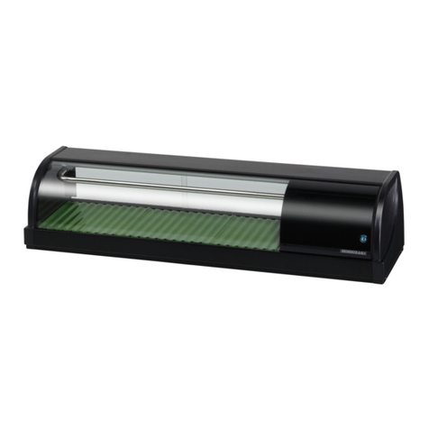
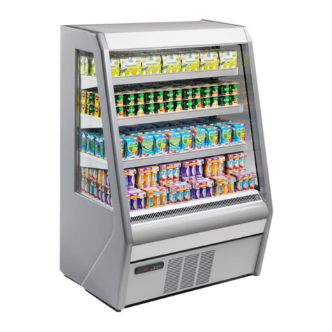
Kysor/Warren HQD6, HQD6L User manual

Part Number: 31E04045
Date: 06/09/2010
5201 Transport Boulevard
Columbus, GA. 31907
706-568-1514 INSTALLATION
&
OPERATION
MANUAL
HQD6, HQD6L, (Q)D6(1)(3), D6L(1)(3), (Q)D6H(1)(3), D6R(1)(3), D6RL(1)(3), D6RLG(1)(3),
D6N(1)(3)
IMPORTANT – KEEP IN STORE FOR FUTURE USE

Part # 31E11012
2/6/2006 1Addendum – Ballast Relocation
INSTALLATION & OPERATION MANUAL ADDENDUM
BALLAST RELOCATION
The ballast for this case has been relocated as of January 09, 2006. The advantage of the new location
allows for more shelf space and lowers the BTU. The information we have placed in this addendum is
for the shelf light ballast only. For any other information, refer to the manual or contact our office at 1-
800-866-5596.
Ballast Location/Connections
Ballasts are located in canopy or the raceway. See wiring diagram for layout.
Canopy Ballast Location
Raceway Ballast Location
1

2/6/2006 2Addendum – Ballast Relocation
2

2/6/2006 3Addendum – Ballast Relocation
WARNING! It is imperative that the pins of the bulbs and the shelf power cords be
completely seated in their respective lamp holder or receptacle (see pictures below). If they are
not completely seated, an electrical arc could occur which will cause the lamp holders to melt and
become an electrical hazard. Care must be taken during cleaning, product stocking and re-
lamping processes to insure that the bulbs and shelf cords are not dislodged.
Note: The fluorescent bulb is capable of lighting even if the bulb and shelf power cord are not
completely seated.
Note: The shelf light harness has power interruption circuit and ALL shelves must be plugged in
correctly before any shelf lights will work. The shelf plugs are now located on the right side of each
back panel. (See picture below).
WARNING! Always disconnect the electrical power at the main disconnect when servicing
or replacing any electrical component. This includes, but is not limited to, such items as fans,
heaters, thermostats and light bulbs. Failure to disconnect the electrical power may result in
personal injury or death.
Bulbs
3

2/6/2006 4Addendum – Ballast Relocation
Wiring Diagram
Both Canopy and Raceway
4

2/6/2006 5Addendum – Ballast Relocation
Wiring Diagram for Canopy Light
5

Introductions – General Information
This manual has been prepared for our customers and the personnel involved in setting up and
maintaining our cases.
The Kysor//Warren multi-shelf self service dairy cases are designed to merchandise packaged
dairy/deli products.
These cases should be installed and operated according to the instructions contained in this
manual to insure proper performance. They are designed for display of products in an air-
conditioned store where temperature and humidity are maintained at a maximum of 75º dry-bulb
temperatures and 55% relative humidity.
CAUTION: Failure to maintain maximum design
conditions may result in operational issues such as: increased
BTUH load, high product temperature, coil icing, product
frosting, and external sweating.
Case Description
Model Description
HQD6 High energy efficient front load dairy case.
HQD6L High energy efficient front load dairy case.
D6L(1)(3) Front load dairy case, Front height 19.5", Standard (4) adjustable shelves 20",
22"
*(Q)D6(1)(3) Front load dairy case, Front height 23.75", Standard (4) adjustable shelves 20",
22", 24"
*(Q)D6H(1)(3) Front load dairy case, Front height 28.25", Standard (4) adjustable shelves 20",
22", 24"
**D6R(1)(3) Rear load dairy case, Front height 23.75", Standard (4) adjustable shelves 20",
22"
**D6RL(1)(3) Rear load dairy case, Front height 19.5", Standard (4) adjustable shelves 20",
22"
**D6RLG(1)(3) Rear load dairy case with glass front, Front height 19.5" plus glass height,
Standard (4) adjustable shelves 20", 22"
**D6N(1)(3) Front load dairy case, Front height 38.25", Standard (5) adjustable shelves 10",
12", 14", 16", 18"
* These models may be used for deli (processed meats) with proper BTU capacity and
Kysor//Warren special hook-a-pack systems are used or 18" and 20" shelves are used above a hook-
a-pack system supplied by others.
** All rear load dairy cases must be installed in a wall of a walk-in cooler where the ambient
temperature is less than 40° F. These cases are not intended to operate as free standing models.
Icon Key
Caution
Special Note
Warning
6

Receiving/Shipping Damage/Lost Items
All equipment should be examined for shipping damage before and during unloading. If there is
any damage, the carrier should be notified immediately and an inspection requested. The
delivery receipt must be noted that the equipment was received damaged. If damage is of a
concealed nature, you must contact the carrier within three (3) days following delivery. The
consignee for all damages must file a claim with the carrier.
NOTE: All claims for shortages must be within 10 days after receipt of shipment.
Refrigerant
A variety of refrigerants can be used in the Kysor//Warren cases provided the correct expansion
valve is equipped with the case when ordered (i.e., R404A required for the end user requires
specifying the correct expansion valve for R404A refrigerant when the order is placed). Multiple
expansion valves are available, depending on end user refrigerant requirements. Expansion
valves are supplied for the refrigerant specified on the original sales order.
In addition, cases can be modified in the field to allow changing the type of refrigerant used.
This requires changing the expansion valve and distributor orifice that is currently equipped in
the case. Contact your Kysor//Warren Service Representative for additional information.
NOTE: Refer to Case Data Control Settings for refrigeration requirements.
Heat Exchangers
Heat exchangers are standard in some models, optional in other models, and are not needed if
mechanical sub-cooling is incorporated in the system design. They are an aid to increasing
operating efficiency and reducing frosting and flood-back to the compressor.
7

Plan Views and Cross Sections
D6L, D6, D6H
8

D6RL, D6R
9

QD6
10

HQD6
811/16
44 1/16
39 11/16
4
23 5/8
6
80 9/16
43 1/8
32 1/16
59 13/16 50 1/16
22
155/8
LOADLIMIT
11

HQD6L
NOTE: For sizing conventional/individual condensing units, add 8% to BTUH load.
Where termination temperatures are given, mechanical defrost termination is required.
8 11/16
44
395/8
4
193/8
80 9/16
43 1/8
5913/16 54 5/16
22
15 5/8
LOAD LIMIT
13/4
32
12

Maximum Shelving Size Recommended
Not to exceed 24”
Case Data
HQD6
CASE DATA AMPS 4’ 6’ 8’ 12’
PSC Fan / # Fans 0.37/1 0.52/ 2 0.74/2 1.11/3
ECM Fan / # Fans 0.30/1 0.60/2 0.60/2 0.90/3
T8 Lights
(per shells) 0.25 0.22 0.25 0.25
LED Lights
(per shelf) 0.11 0.09 0.11 0.11
T8 Lights
(Canopy, 1 row) 0.25 0.40 0.50 0.75
LED Lights
(Canopy, 1 row) 0.24 0.36 0.48 0.72
T8 Lights
(Noselight) 0.25 0.40 0.50 0.75
LED Lights
(Noselight) 0.11 0.18 0.22 0.33
All electrical data based on 115V and unlighted shelves.
DEFROST CONTROLS
Defrost Per Day Fail Safe Termination
Off Cycle 3 40 min 48°F
Hot gas 3 20 min 48°F
BTUH per FT of Case
PSC Fan 1260
ECM Fan 1230
Add BTUH per FT of Lighted Shelf
T8 19
LED 11
CAPACITIES
13

4’ 6’ 8’ 12’
Facing Area 16.8 ft225.1 ft233.5 ft250.2 ft2
Cubic Capacity 47.8 ft371.6 ft395.5 ft3143.2 ft3
Evap Temp Discharge Air
Velocity
(1 hr. after Defrost)
Discharge Air
Temp
30°F 250 FPM 34°F
Evaporator Temp = 27°F when lighted.
Discharge Air Temp = 32°F when lighted.
HQD6L
CASE DATA AMPS 4’ 6’ 8’ 12’
PSC Fan / # Fans 0.37/1 0.52/ 2 0.74/2 1.11/3
ECM Fan / # Fans 0.30/1 0.60/2 0.60/2 0.90/3
T8 Lights
(per shells) 0.25 0.22 0.25 0.25
LED Lights
(per shelf) 0.11 0.09 0.11 0.11
T8 Lights
(Canopy, 1 row) 0.25 0.40 0.50 0.75
LED Lights
(Canopy, 1 row) 0.24 0.36 0.48 0.72
T8 Lights
(Noselight) 0.25 0.40 0.50 0.75
LED Lights
(Noselight) 0.11 0.18 0.22 0.33
All electrical data based on 115V and unlighted shelves.
DEFROST CONTROLS
Defrost Per Day Fail Safe Termination
Off Cycle 3 40 min 48°F
Hot gas 3 20 min 48°F
BTUH per FT of Case
PSC Fan 1350
14

ECM Fan 1320
Add BTUH per FT of Lighted Shelf
T8 19
LED 11
Capacities
4’ 6’ 8’ 12’
Facing Area 16.8 ft225.1 ft233.5 ft250.2 ft2
Cubic Capacity 47.8 ft371.6 ft395.5 ft3143.2 ft3
Evap Temp Discharge Air
Velocity
(1 hr. after Defrost)
Discharge Air
Temp
30°F 250 FPM 34°F
Evaporator Temp = 27°F when lighted.
Discharge Air Temp = 32°F when lighted.
QD6
CASE DATA AMPS 4’ 6’ 8’ 12’
STD Fan / # of Motors 0.52/1 0.70/1 1.04/2 1.56/3
PSC Fan / # of Motors 0.26/1 0.44/1 0.52/2 0.78/3
ECM Fan / # of Motors 0.25/1 0.40/1 0.50/2 0.75/3
T8 Lights (Canopy,1 Row) 0.25 0.40 0.50 0.75
T8 Lights (per shelf) 0.25 0.22 0.25 0.25
Electric Defrost (Electric
- 230V) 3.30 5.61 7.93 11.54
All electrical data based on 115V and unlighted shelves.
DEFROST CONTROLS
Defrost Per Day Fail Safe Termination
Off Cycle 4 30 48°F
15

Hot gas 4 20 48°F
BTUH per Ft - Unlighted Shelves
STD Fan 1300
PSC Fan 1290
ECM Fan 1275
NOTE: For sizing conventional/individual
condensing units, add 8% to BTUH load.
*For lighted shelves, please add 19 BTUH.
Evap Temp Discharge Air
Velocity Discharge Air
Temp
+23°F 275 FPM +31.5°F
CAPACITIES
4’ 6’ 8’ 12’
Facing Area (ft
2
) 16.8 25.1 33.5 50.2
Cubic Capacity (ft
3
) 42.2 63.2 84.3 126.4
(Q)D6 (Q)D6L (Q)D6H
4 Foot 6 Foot 8 Foot 12 Foot
Cubic Capacity 40.1 cf 60.2 cf 80.2 cf 120.3 cf
#Defrosts/Failsafe (Off-Cycle) 4/40 4/40 4/40 4/40
#Defrosts/Failsafe (Electric) (not on Q) 4/30 4/30 4/30 4/30
#Defrosts/Failsafe (Hot Gas) 4/20 4/20 4/20 4/20
Temp. Termination Hot Gas (all except
Q))
+55 ºF +55 ºF +55 ºF +55 ºF
Temp. Termination Hot Gas (Q) +48 ºF +48 ºF +48 ºF +48 ºF
Superheat Setting 6-8 °F 6-8 °F 6-8 °F 6-8 °F
Dairy - Discharge Air Temp (all except
Q)
28-32
°F
28-32 °F 28-32
°F
28-32 °F
Deli - Discharge Air Temp (all except Q) 24-28
°F
24-28 °F 24-28
°F
24-28 °F
Dairy or Deli - Discharge Air Temp (Q)
30-32
°F 30-32 °F
30-32
°F 30-32 °F
D6N
8 foot 12 Foot
16

Cubic Capacity 75.10 cf 112.66 cf
#Defrosts/Failsafe (Off-Cycle) 4/40 4/40
#Defrosts/Failsafe (Electric) 4/30 4/30
#Defrosts/Failsafe (Hot Gas) 4/20 4/20
Temp. Termination Hot Gas (All modes) +55 ºF +55 ºF
Superheat Settings 6-8 ºF 6-8 ºF
Dairy - Discharge Air Temp 28-32 ºF 28-32 ºF
Deli - Discharge Air Temp 24-28 ºF 24-28 ºF
D6R, D6RL, D6RLG
4 Foot 6 Foot 8 Foot 12 Foot
Cubic Capacity 40.1 cf 60.2 cf 80.2 cf 120.3 cf
#Defrosts/Failsafe
(Off-Cycle)
4/40 4/40 4/40 4/40
#Defrosts/Failsafe
(Electric)
4/30 4/30 4/30 4/30
#Defrosts/Failsafe
(Hot Gas)
4/20 4/20 4/20 4/20
Temp.
Termination Hot
Gas
+55 ºF +55 ºF +55 ºF +55 ºF
Superheat Setting 6-8 °F 6-8 °F 6-8 °F 6-8 °F
Discharge Air
Temp 28-32 °F 28-32 °F 28-32 °F 28-32 °F
NOTE: The air current is very important to the performance of this case. The load
limit line (see load case sction) is the indicator of the inside edge of the air current and at no
time should shelving, product, signs, debris, etc., interfere with air current.
NOTE: Temperature is measured in discharge air. Defrost frequency is at design
conditions. Higher temperature or humidity may require more defrost and longer fail-safes.
These cases are not designed to operate in environments where the ambient temperature is
greater than 75ºF and the relative humidity is greater than 55%. Off-cycle defrost is the
recommended defrost for these cases. Hot gas defrost is available for installations requiring a
positive defrost. Refer to www.kysorwarren.com for other electrical data and information.
17

CAUTION: Failure to maintain maximum design conditions may result in operational
issues such as: increased BTUH load, high product temperature, coil icing, product frosting, and
external sweating.
CAUTION: Failure to properly install electrical wiring and control wiring as per wiring
diagram(s), defrost settings, and temperature set-points may result in operational issues such as:
increased BTUH load, high product temperature, coil icing, product frosting, and external
sweating.
Conversion from Wattage to Amps for Single phase cases:
Power = (Voltage)(Current)
Watts = (Volts)(Amps)
Watts/Volts = Amps
18

UNIT INSTALLATION
These display cases may be installed individually or in a continuous line up consisting of several
4’, 6’, 8’ and 12’ sections using a joint kit. A Plexiglas divider kit must be used between cases
operating on different refrigeration systems. The divider will be factory installed if specified on
order.
Shipping Damage
All equipment should be examined for shipping damage before and during unloading. If there is
any damage, the carrier should be notified immediately and an inspection requested. The
delivery receipt must be noted that the equipment was received damaged. If damage is of a
concealed nature, you must contact the carrier within three (3) days following delivery. A claim
must be filed with the carrier by the consignee for all damages.
Note: All claims for shortages must be within 10 days after receipt of shipment.
Installation Location and Preparation
Proper installation of the case ensures maximum case life and ensures all future warranty claims,
if required, will be honored. Review the following instructions and contact your Kysor//Warren
Service Representative if there are any questions or concerns.
Location and Special Precautions
Caution: Influences, such as heating and air conditioning outlets and outside
entrances, may adversely affect the operation of the case. Damage to case contents may
occur if case temperature is not properly maintained. Follow all recommendations for
case installation.
Caution: To prevent condensation on the end panels of cases, a minimum of 6.0
inches between walls or other units is required for air flow. If 6.0 inches is not
possible, then the space between the units must be completely filled and sealed or an
updraft fan kit must be installed to provide air circulation through the space.
Caution: The installation area must be clean of all debris that may restrict airflow or
otherwise inhibit proper installation. In addition, it is recommended that all
refrigeration units are located at least 15 feet away from outside entrance doorways or
heating and air conditioning outlets that may adversely affect case temperature.
19
This manual suits for next models
21
Table of contents
Other Kysor/Warren Display Case manuals