L.B. White AS040 User manual

August 1999
2.9-33
Model AAS040 ((Cont.)
7. Attach the ground lead terminal to the ground screw in
the enclosure.
8. Push the exposed conductors of the power supply and
return leads beneath the terminal strip screw plates
previously occupied by the jumper. Tighten the screw
plates and tug on the leads to make sure the leads are
securely attached.
9. Reconnect the heater to its electrical supply and open
the fuel supply valves to the heater.
10. Check the heater for proper operation. Light the pilot
and set the thermostat so the fan motor starts and the
main burner ignites.
11. Disconnect the heater from its electrical supply.
Reinstall the electrical enclosure cover and the fan
access panel. Reconnect the heater to its electrical
supply. Set the thermostat to desired temperature.
Model AAB200 aand AAB250
1. Disconnect the heater from its electrical supply and
close all fuel gas valves to the inlet of the heater.
2. Open the burner access door to locate the heater’s
electrical enclosure. Remove the cover from the
enclosure.
3. Remove the hole plug from the thermostat cord entry
hole near the power cord at the front of the case
assembly.
4. Run the thermostat cord through this hole and through
the bushing in the base of the enclosure.
Remote Thermostat
Installation
Instructions
Ground
Lead

2.9-44
August 1999
Model AAB200 aand AAB250
5. Secure the cord in place at the entry hole on the case
front with the strain relief provided in the thermostat kit.
6. Loosen the terminal strip screws that hold the jumper in
place. Remove the jumper.
7. Push the exposed conductors of the power supply and
power return leads beneath the terminal strip screw
plates previously occupied by the jumper. Tighten the
screw plates and tug on the leads to make sure the
leads are securely attached.
8. Attach the ground lead terminal to the ground screw in
the enclosure.
9. Reconnect the heater to its electrical supply and open
the fuel supply valves to the heater.
10. Light the pilot. Set the thermostat so the fan motor
starts and the burner lights. Check the heater for proper
operation.
11. Set the thermostat to the desired temperature.
Reinstall the electrical enclosure cover.
Remote Thermostat
Installation
Instructions

1. Assemble according to the illustration and tighten all
eyebolts securely.
2. Make sure the heater is properly positioned before
use and is hung level. Observe and obey all minimum
safe distances of the heater to the nearest
combustible materials. Minimum safe distances are
given on the heater dataplate.
3. See figure for typical indoor installation. In any animal
confinement building, consideration must be given to
making sure the heater is located away from the
livestock so that livestock cannot knock the heater,
tear it loose from its mounting, or damage the heater,
its power supply cord, or its gas supply line in any way.
Make sure you observe and obey minimum clearance
distances to combustible materials as stated in the
specification section of this owner’s manual and on
the heater itself.
Hanging Instructions
Installation
Instructions
2.10-11August 1999
Cage Nut
OPTIONAL INDOOR
REGULATOR
MOUNTING LOCATION
GAS HOSE
THERMOSTAT
CORD
YOKE
HEATER
THERMOSTAT 30.5CM 30.5CM
BLACK PIPE
THROUGH WALL
VENT LINE
WALL OUTLET
POWER CORD
SEDIMENT
TRAP
WALL
CHAIN OR CABLE
12 IN. See
Spec.
Tables

Air Diverters
Installation
Instructions
Depending on model number, two designs of air diverters
may be available for your heater. The air diverters allow the
hot discharge air to be blown out either in two 45 degree
paths or in one direction only (two-piece diverter kit only).
Either way promotes good air movement and circulation.
Two-PPiece AAir DDiverter
1. Install the air diverter as follows. This is a typical
procedure for all heaters. Appearance of the outlet on
heater may vary from model to model.
a. The air diverter’s notched tabs on each half will
pop into the blower outlet between the inside of
the case assembly and the blower housing outlet.
If the notched tabs do not pop into the blower
outlet, loosen (do not remove) the blower outlet
screws. Doing this provides a gap into which you
can insert the tabs.
b. The air diverter halves are installed so the notches
in the tabs are up against the formed guard of the
blower outlet.
c. Tighten blower outlet screws.
August 1999 2.11-11
Diverters PPointed iinOOne DDirection
Diverters PPointed BBoth LLeft aand RRight

Air Diverters
Installation
Instructions
August 1999
2.11-22
One-PPiece AAir DDiverter
1. Loosen the four blower outlet screws.
2. Align the keyhole slots in the mounting flanges with
each outlet screw.
3. Push down on the diverter to lock it into position.
Tighten the outlet screws.
ATTENTION
Larger design air diverters for Models 377/379, 408/410,
and AB200 heaters incorporate holes in the “Y” of the
assembly to allow ease of mounting to the heater outlet.
Keyhole Slots

Start-UUpIInstructions
Determine the pilot control valve type supplied on the heater.
For heater with gas control valves with an internal low
pressure regulator and gas shut off, refer to Section A.
For heaters with gas control valves without an internal low
pressure regulator and gas shut-off, refer to Section B.
Follow all procedures within the appropriate section on initial
start-up after heater installation by qualified gas heater
service person. For normal start-up simply turn the
thermostat above room temperature. The heater will start.
ATTENTION
■On new installations it may take about a minute for
the gas to purge out any air in the pilot line before the
pilot stays lit.
SECTION AAControl VValves wwith IInternal
Low PPressure RRegulator aand GGas
Shut-OOff
1. Open all manual fuel supply valves and check for gas
leaks using approved leak detectors.
2. Remove the metal cover from the control enclosure (if
applicable).
3. Position the indicator arrow on the control valve’s
shut-off knob to “pilot”.
4. Fully depress the pilot button while applying flame to
the pilot burner.
5. Keep the button depressed for about 30 seconds to
allow the thermocouple to warm up so the pilot stays
lit after the pilot button is released.
6. Position the knob to “on”.
7. Reinstall the metal cover (if applicable).
8. Connect the heater’s power cord to an approved
electrical supply.
9. Set the thermostat above room temperature. The
heater will light.
10. Reset the thermostat to desired room temperature.
SECTION BBControl VValves wwithout IInternal
Low PPressure RRegulator aand
Gas SShut-OOff ((Part 5500-002309)
1. Open all manual fuel supply valves to the heater and
check for gas leaks using approved leak detectors.
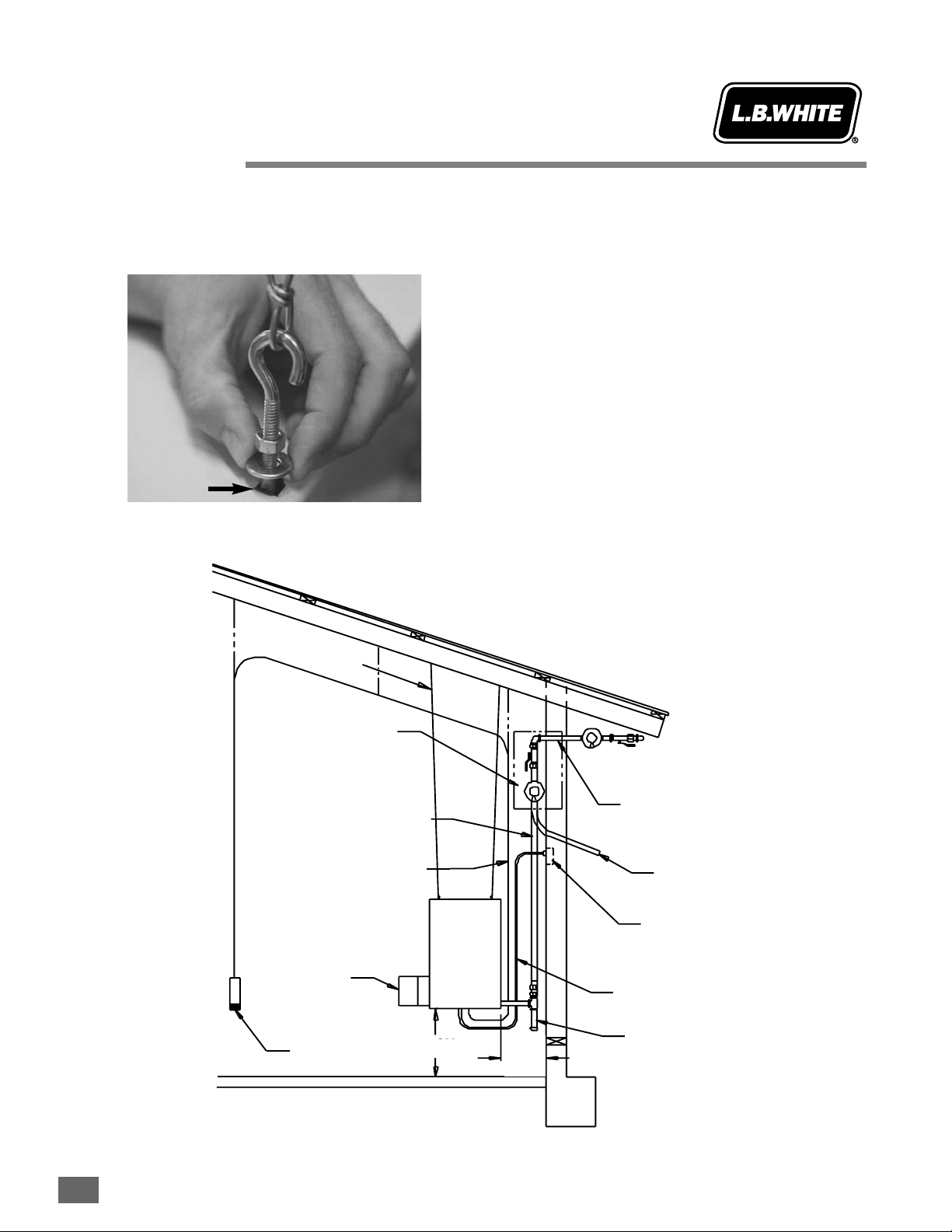
2. Fully depress the pilot button while applying flame to
the pilot burner.
3. Keep the button depressed for about 30 seconds to
allow the thermocouple to warm so the pilot stays lit
after the pilot button is released.
ATTENTION
■The red cap protecting the pilot control may become
stiff in colder temperatures.
■Remove the cap and fully depress the pilot button to
light the pilot. Reinstall the cap.
4. Connect the heater’s power cord to an approved
electrical supply.
5. Set the thermostat above room temperature. The
heater will light.
6. Reset the thermostat to desired room temperature.
August 1999 3.1-11
Pilot
Button
Knob
Pilot
Button
Start-Up and Shut-Down Instructions
Operation
Instructions

Start-Up and Shut-Down Instructions
Operation
Instructions
Shut-DDown IInstructions
If the heater is to be shut down for cleaning, maintenance, or
repair, follow steps 1 through 5. Otherwise, simply turn the
thermostat to “Off” or “No Heat” for standard shut down.
1. Close all manual fuel supply valves.
2. With heater lit, allow heater to burn off remaining fuel
in gas supply hose.
3. If applicable, turn the control valve knob to “Off”.
4. Turn thermostat to “Off” or “No Heat” position.
5. Disconnect the heater from its electrical supply.
August 1999
3.1-22

Variable Heat Output
Operation
Instructions
3.2-11
1. Some models of propane (LP) gas or natural gas
heaters have a throttle valve for varying heat output
located between the gas control valve and gas
manifold assemblies. THIS IS NOT A MANUAL GAS
SHUT OFF VALVE.
2. The throttle valve can be adjusted to deliver either
minimum heat or maximum heat. Become
familiarized with the design of the throttle valve in your
heater. Refer to the illustrations below to determine
valve location and how to adjust the heat output.
August 1999
Handle
Parallel
MAXIMUM HEAT
MINIMUM HEAT
75% OF MAXIMUM
90% OF MAXIMUM
Handle
Turned 990º
MANIFOLD
IN
CREASE
CRE
E
S
A
E
D


Periodic Inspection
Preventative
Maintenance
1. The aarea ssurrounding tthe hheater sshall bbekkept cclear
and ffree ffrom ccombustible mmaterials, ggasoline, aand
other fflammable vvapors aand lliquids.
2. Have your gas supplier check all gas piping annually
for leaks or restrictions in gas lines. Also, at this time
have your gas supplier clean out the sediment trap of
any debris that may have accumulated.
3. Regulators must be periodically inspected to make
sure the regulator vents are not blocked. Debris,
insects, insect nests, snow, or ice on a regulator can
block vents and cause excess pressure at the
appliance.
4. Regulators can wear out and function improperly.
Have your gas supplier check the date codes on all
regulators installed and check delivery pressures to
the appliance to make sure that the regulator is
reliable.
5. Check all wiring associated terminals and electrical
components within the heater for corrosion, frayed or
cut insulation, tight connections, etc. Repair or
replace as necessary.
6. Review all heater markings (i.e. wiring diagrams,
warnings, start-up, shut-down, troubleshooting, etc.)
at the time of maintenance for legibility. Make sure
none are cut, torn, or otherwise damaged. Any
damaged markings must be replaced immediately by
contacting the L.B. White Co., Inc. Dataplates, start-
up and shut-down instructions and warnings are
available at no cost. A nominal charge will be applied
for wiring diagrams, and troubleshooting markings.
August 1999 4.1-11

Cleaning Instructions
Preventative
Maintenance
4.2-11
1. Before cleaning, shut off all gas supply valves and
disconnect electrical supply.
2. The heater should have dirt or dust removed
periodically:
a. After each flock or between building re-population,
give the heater a general cleaning using
compressed air or a soft brush on its interior and
exterior. At this time, dust off the motor case to
prevent
the motor from over-heating and shutting
the heater down.
b. At least once a year, give the heater a thorough
cleaning. At this time, remove the fan and motor
assembly and brush or blow off the fan wheel,
giving attention to the individual fan blades.
Additionally, make sure the burner air inlet venturi
ports and the throat of the casting are free of dust
accumulation and the area between the heat
chamber top and inside case is also free of dust.
c. Observe and obey all instructional warnings
pertaining to cleaning procedures located on each
heater.
August 1999
WARNING
Fire, BBurn, aand EExplosion HHazard
■This heater contains electrical and mechanical components in the gas management, safety and airflow systems.
■Such components may become inoperative or fail due to dust, dirt, wear, aging, or the corrosive atmosphere of an
animal confinement building.
■Periodic cleaning and inspection as well as proper maintenance are essential to avoid serious injury or property
damage.

Troubleshooting Guide
Troubleshooting
Instructions
READ THIS ENTIRE SECTION BEFORE
BEGINNING TO TROUBLESHOOT PROBLEMS.
The troubleshooting flow charts in this section provide
systematic procedures for isolating heater problems. Refer
to the Component Testing section of this Service Guide for
general instructions on performing voltage and continuity
checks as well as evaluation of specific components as
indicated by these charts. Refer to the appropriate wiring
diagram for assistance in performing voltage and continuity
checks. Refer to the Service section for gas pressure checks
and adjustments as indicated by the flow charts.
TEST EQUIPMENT REQUIRED
The following pieces of test equipment will be required to
troubleshoot this system with minimal time and effort.
• Digital MMultimeter - for measuring voltage and resistance.
• Thermocouple TTest KKit - (L. B. White Part No. 500-08506)
When used with a standard digital multimeter, this kit
allows testing of the power unit of the pilot safety control
and thermocouple on pilot ignition systems.
• Low PPressure GGauge - (L.B. White Part No. 550-00764) for
checking inlet and manifold pressures of the gas control
valve against dataplate rating.
INITIAL PREPARATION
■Visually inspect heater for apparent damage.
■Check all hoses for abrasion and wear. Replace any
that are suspect.
■Make sure heater is properly installed and meets
minimum clearances to nearest combustible materials.
(Refer to dataplate on heater.)
■Check all wiring for loose connections and worn
insulation.
To effectively use these flow charts, you must first identify
the problem. The problems are numbered sequentially,
along with a brief explanation of each problem. Start at the
“diamond” closest to the identified problem and proceed
with each step, performing the suggested tests. After each
step or test, the guide will direct the service person to the
next logical step based on the outcome of the previous
check.
The problems are listed below along with the page number
on which you may find the flow chart for the specific
problem.
Problem Description Page
1 Pilot will not light 5.1-3
2 Pilot will not stay lit when pilot control
button is released 5.1-4
3 Motor runs. Burner does not light with
pilot light lit. 5.1-5
4 Motor does not run, heater does not light
with pilot light lit. 5.1-6
5 Main burner cycles on and off repetitively.
Pilot stays lit. 5.1-7
6 Pilot will not stay lit when main burner
and blower are operating. 5.1-7
7 High limit switch is open. 5.1-8
8 Burner does not shut off. 5.1-9
9 Flame “lifting” off of burner. 5.1-9
10 Burner flame drops out after 10 - 15
minutes of operation. 5.1-9
11 Gas control valve “chatters”. 5.1-10
12 Motor “hums”. 5.1-10
13 Heater is not delivering proper air flow 5.1-11
14 Heater is not delivering proper heat output 5.1-11
Components should be replaced only after each step has
been completed and replacement is suggested in the flow
chart. Refer to the Servicing sections as necessary to obtain
information on disassembly and replacement procedures of
the component once the problem is identified by the flow
chart.
Additionally, a series of illustrations has been provided on
the following page to identify typical problems based upon
pilot flame appearances.
August 1999 5.1-11
WARNING
Electrical SShock aand BBurn HHazard
■Do not attempt to service or repair this heater unless
you are a properly trained and qualified gas heater
service person.
■Troubleshooting this system may require operating the
unit with line voltage present and gas on. Use extreme
caution when working on the heater.
■Failure to follow this warning may result in property
damage, personal injury or death.

Troubleshooting Pilot Flame
Troubleshooting
Instructions
August 1999
5.1-22
ATTENTION
■These illustrations are intended to provide a means to
assist you in troubleshooting a pilot problem. They
must be used in conjunction with proper cleaning,
checking for proper gas pressures, etc.
■With any pilot light assembly, always make sure the
thermocouple is completely installed within the pilot
bracket by either its mounting clip or nut.
1. Correct Flame 4. Wavy Blue Flame
2. Noisy, Lifting Flame 5. Hard, Sharp Flame
3. Lazy, Yellow Flame 6. Small, Blue Flame
Pilot flame
spreader
head
Thermocouple
Check for:
* Excessive drafts
* Pilot shield
loose
Check for:
* High gas pressure
* Improper pilot
orifice
Check for:
* High gas pressure
* Improper orifice
* Partially plugged
pilot orifice or dirty
pilot assembly
Check for:
* Partially plugged
pilot orifice or pilot
tubing
* Low gas pressure
* Dirty pilot assembly
Check for:
* Improper pilot orifice
* Low gas pressure
* Partially plugged pilot
orifice or
pilot tubing
3/8 in. to 1/2 in.

August 1999 5.1-33
Problem 1
Pilot will
not light.
Is
LP gas cylinder
or tank full? Yes
No
Yes Yes
Yes Yes
Are all fuel
supply valves
open?
Remove these
components and
blow out with
compressed air.
Fill container if low. Open all supply valves. Is the
pilot control
button fully
depressed?
Replace pilot
Is there air in
the gas line?
No No
Fully depress the
pilot button.
No No No
Yes Depress pilot
button to bleed
off the air until
pilot lights.
(Normally 30 -
45 seconds.)
Check for proper fuel
pressure to inlet of
heater. Adjust as
Is the
correct pilot
orifice installed
for the fuel being
used?
Is
there a
restriction in gas
supply hose, pilot
tube or pilot
orifice?

Problem 2
Pilot will
not stay lit
when pilot
control
button is
released.
Is LP
gas supply
cylinder tank
full?
Yes
No
Yes Yes Yes Yes
Did
you allow
sufficient time to
allow thermocouple
warm up?
Is
thermocouple
contact nut
tight?
Is
thermocouple
properly positioned
in pilot
bracket?
Fill container if low. Allow 30 - 60 seconds
warm up before releasing
pilot button.
Snug nut in place. (Do
not overtighten.) Pilot flame should
impinge on 3/8 - 1/2 in.
of thermocouple tip.
Disassemble and
clean with
compressed air. Do
not use pointed
instruments. Replace
pilot orifice if
Is
pilot assembly,
including orifice,
clean?
Are
pilot line
or gas supply
hose partially
plugged?
Yes Remove and clean
with compressed air.
No No No
Check for proper
pressure to heater
inlet. Refer to
heater nameplate.
Replace with proper
pilot orifice.
No
No
Check millivolt output. 10
MV or greater is acceptable.
Replace thermocouple if
less than 10 MV (with
burner off).
No
Yes
Did you
check for dirt or
debris between
thermocouple contact
and electromagnet
of valve?
Check for debris
between contact of
thermocouple and
electromagnet of valve.
No
Yes Is proper pilot
orifice installed? Yes Has
thermocouple
strength been
checked with
tester?
Yes Has drop
out of safety magnet
on pilot control been
checked?
Is
proper gas
pressure supplied
to heater?
No
No
Check millivolt dropout. 4 MV or less
is proper. Over 4 MV is weak valve.
Replace entire valve.
No
August 1999
5.1-44

August 1999 5.1-55
Problem 3
Motor runs.
Burner
does not
light with
pilot light
lit.
For units with air proving
switch or centrifugal switch,
is proper voltage being
delivered to the
switch?
Yes
No
Yes Yes
Yes
Yes
Are air proving
switch or centrifugal
switch contacts opening
and closing properly?
(Perform a continuity
check.)
Is flapper
(if applicable)
binding? Repair or replace flapper.
Check voltage supply,
electrical connections to
switch and wires for
continuity. Repair as
necessary.
Replace air proving switch
or for units with centrifugal
switch, replace motor.
Is
flapper arm
(if applicable)
engaging switch
arm properly?
Adjust flapper arm to
engage switch arm or clean
out any debris from around
flapper or air flow switch.
Tighten set screws
to motor shaft.
Reset switch.
Determine cause of
high limit tripping.
(See Problem 7.)
Yes Clean out debris.
Check electrical connections
to high limit switch and to control valve
and check wires for continuity.
Check for proper pressure
using low pressure gas gauge.
Refer to heater nameplate.
Yes Yes
Have
you checked
for proper inlet and
burner manifold pressure
at gas control valve?
If proper gas pressure is supplied to the
inlet of the gas control valve, but burner
manifold pressure is not apparent, then
replace the control valve.
Is high limit
switch
tripped?
No
No
No
Are
burner
orifice, burner
casting or manifold
plugged?
No
No No
Yes
Is
fan tightened
properly to motor
shaft?
No
Is proper voltage
supplied to and
from high limit
switch to control
valve?
No

Problem 4
Motor does
not run,
heater
does not
light with
pilot light
lit.
Is
proper voltage
supplied to
heater power
cord?
No
Yes
Yes Yes Yes
Yes Yes
Is
thermostat set
above room
temperature?
Is
proper voltage
supplied to
thermostat?
Is
proper voltage
supplied to
motor?
Do
thermostat
contacts “open and
close”? (Perform
continuity
check.)
Provide proper voltage.
See heater nameplate.
Check circuit breaker
in electrical system.
Set thermostat above
room temperature. Check electrical
connections to thermostat
and power cord.
Are
electrical
connections to
motor installed
properly?
Defective motor.
Replace.
Is fan
wheel binding?
Repair,
condition or
replace fan
wheel.
No No No No No
Repair or replace
wires and
connections.
Defective thermostat.
Replace.
No
August 1999
5.1-66

Problem 5
Main burner
cycles on
and off
repetitively.
Pilot stays
lit.
Air proving
switch arm is
out of
adjustment.
Readjust flapper arm.
Bend arm up slightly with
needle nose pliers.
Is
outlet of heater
free from
blockages?
Problem 6
Pilot light
will not
stay lit
when main
burner and
blower are
operating.
Have you checked for
proper fuel use and inlet
gas pressure?
Yes
Yes
No
Check for proper
pressure. Make sure
proper fuel is being used
for appliance installed.
No
Remove blockages.
Is pilot shield (and
gasket, if applicable) in
proper position and tight
against burner?
No
Tighten pilot shield
screws to close gap
between shield and
orifice. Make sure gasket
(if applicable) is
positioned properly.
August 1999 5.1-77

Problem 7
High limit
switch is
open. Is fan loose
or dirty? Yes
No
Yes Yes
Yes Yes
Tighten fan wheel set
screw(s) to motor
shaft. Blow fan with
compressed air or
clean with soft brush.
Are
there restrictions
at air inlet or
outlets (such as
unapproved
ductwork)?
On heaters without
air proving switch, is
motor overheating
and shutting down?
Have you checked for
proper gas type being
used, pressure or for
liquid propane in line?
Check building electrical
system. Repair as
necessary. See heater
nameplate for correct
voltage.
Is
proper voltage
being supplied
to motor?
Is heater
reasonably
clean? Remove restriction.
No
No
No
No
Give heater a
thorough cleaning
with a soft brush or
compressed air.
DO NOT USE WATER
OR ANY LIQUID
CLEANING AGENTS.
No
Yes
Motor is defective.
Replace.
Clean motor housing.
Is motor dirty?
No
Check for proper fuel and pressure on
nameplate of heater. Correct as necessary.
August 1999
5.1-88

Problem 8
Burner does
not shut
off when
temperature
requirement
is satisfied.
Does
thermostat shut
off within ± 3° F.
of set point?
Yes
No
Debris is lodged
in seat of gas
control valve.
Replace entire
valve.
Replace thermostat.
Problem 9
Flame
“lifting”
off of
burner.
Has gas
pressure been
checked?
Yes
No
Yes
Are there blockages in
burner casting, burner orifice or
primary air inlets of casting? Clean with compressed air.
Check for proper pressure
to inlet of heater and also
for proper burner manifold
pressure.
Problem 10
Burner
flame drops
out after
10 - 15
minutes of
Is
gas supply
line and tank
properly
sized?
Yes
No
See problem 3 and 6.
Resize line and reselect
larger tank size if necessary.
August 1999 5.1-99
This manual suits for next models
2
Table of contents
Popular Thermostat manuals by other brands

First
First ELTHERM TT 6 user guide

Radimo
Radimo Radistat-Pro user guide

Aprilaire
Aprilaire 8910 Safety & installation instructions

Carrier
Carrier ComfortVu TB-24-HM Installation and operation guide

Lennox
Lennox ComfortSense 8500 Series Installation and setup guide

Honeywell
Honeywell PRO 2000 Series operating manual

Siemens
Siemens RDD310/EH user manual

Siemens
Siemens Powers ET 134 Technical instructions

Neptronic
Neptronic ARO24T installation instructions

Network Thermostat
Network Thermostat RP32-NX Installation and programming instructions

XCI Controls
XCI Controls TrueTouch TSZ-2 instruction manual

Heatmiser
Heatmiser PRT-ETS WiFi operating instructions