L-Tronics Little L-Per LL Series User manual

LL Series Little L-Per®
Portable Direction Finder
OPERATING MANUAL

2
Table of Contents
Introduction ....................................... 3
Details on the Operating
Screen (Display) ........................... 4
Assembly for Operation .................... 5
Summary of Operating Modes .......... 5
Details on Operation ......................... 6
Operation in the DF Mode.............. 7
Operation in the Receive Mode ..... 7
Calibration...................................... 7
Changing Frequency...................... 8
Storing a Frequency....................... 9
Using External Antennas .................. 9
Other Adjustable Values ................... 9
SET1 ................................................. 9
External Power and Audio ................10
Odds and Ends .................................10
More About Batteries ........................11
Direction Finding Techniques ...........13
Determining Bearing Reliability.........13
Reliability Circle .............................13
Walking a Baseline ........................13
Radio Signal Propagation .................13
Reflectors ......................................... 14
Reflectors Near the Transmitter .... 14
Reflections Near the Receiver....... 14
Blocked Signal, Single Reflector ...... 14
Blocked Signal, Multiple Reflectors 14
Resolving Multiple Reflections....... 14
Direction Finding Inside a Building ... 15
Using the L-Per®in the
Fore/Aft Mode............................... 15
Horizontal Polarization...................... 15
List of Figures
Figure 1. Display Screen
Condition Indicators...................... 4
Figure 2. Operating Position
for all Frequencies ........................ 5
Figure 3. L-Per®Operating
Screen in the DF Mode................. 6
Figure 4. L-Per®Operating
Screen in the Receive Mode ........ 6
Specifications
¾Battery operated double conversion superhetrodyne receiver with built-in tunable active an-
tennas.
¾Frequency range 108 - 173.9999 and 215 - 269.9999 MHz.
¾First IF 21.4 MHz. Second IF 455 kHz.
¾Acceptance bandwidth 7 kHz.
¾Image and spurious rejection >60 dB.
¾Operating temperature range -20 to +60 C.
¾Frequency stability @25 C <±5 ppm, full temp <±20 ppm.
¾Selectable FM or logarithmic AM detection.
¾Sensitivity at BNC jacks <-123 dBm for 12 dB SINAD FM, 6 dB s/n AM.
¾Minimum trackable CW signal, left/right display <-132 dBm; receive mode with BFO <-140
dBm.
¾Max signal for left/right DF >+5 dBm.
¾Power 6 AA batteries or external 6-28VDC.
¾Current 45 mA lights off, low volume, 85 mA lights on, 150 mA lights on and full volume.
¾Typical alkaline battery life 30 hours
¾Audio output 0.3W, 8 ohms. Weight with batteries 29 oz.
Indicates areas of latest revisions.
Copyright 2006 and 2008 by L-Tronics®, 5546 Cathedral Oaks Rd., Santa Barbara, CA 93111.
www.ltronics.com. All rights reserved.
March 2008

3
LL Series Little L-Per®Portable Direction Finder
OPERATING MANUAL
INTRODUCTION
The LL Series portable direction finder is
a compact, hand-held, synthesized receiver
with tunable, folding antennas capable of
receiving AM and FM signals. The sealed
case is high-impact plastic and all exposed
metal is stainless steel for corrosion resis-
tance. A finger-operated, gasketed plug al-
lows the AA batteries to be quickly replaced.
External antenna jacks allow for connection
of L-Tronics®magnetic, flexible, and aircraft
antennas, as well as other antennas such
as beams. A third connector on top of the
receiver can be used for external power and
earphones.
AN OPERATING INSTRUCTION SUM-
MARY IS PRINTED ON THE LEFT SIDE
OF THE FRONT PANEL. PLEASE REFER
TO IT FREQUENTLY UNTIL YOU BE-
COME FAMILIAR WITH THE EQUIPMENT
AND ITS OPERATION.
The DF display shows direction and sig-
nal strength simultaneously, along with
other information as shown in figure 1. Both
the display and the keyboard can be lit for
night use.
The receiver is pre-programmed with
121.5 MHz in Channel 1, 243.0 MHz in
Channel 2, 121.775 MHz in Channel 3, and
Marine calling frequency 156.8 MHz in
Channel 4. These frequencies cannot be
changed by the customer. Six additional
memories can be programmed by user from
the keyboard.
Direction finding techniques are the
same with this equipment as they are with
the older style LH Series Little L-Per®.
There are some important differences in the
operation of this equipment. With the LL Se-
ries:
1. It is not necessary to change anten-
nas when changing frequencies.
2. The display shows left-right homing
and signal strength (by number and
scale) simultaneously.
3. The receiver is programmable on
any frequency from 108 MHz to 174
MHz and 215 MHz to 270 MHz.
4. The antenna system needs to be
calibrated periodically with the CAL
key (see instructions).
5. The unit is not field repairable inter-
nally; breaking the security seals
between the case halves will void
the warranty.
Attention!!
For those of you who “Don’t do manuals,” please make
an exception and read this one at least once. It’s not
that long or hard. If you prefer to guess or believe fairy
tales from friends and then screw it up, you will get little
sympathy from us.

4
DETAILS ON THE OPERATING SCREEN (DISPLAY)
Figure 1. Display Screen Condition Indicators
Figure 1 shows the operating screen in
DF mode illustrating the various condition
indicators.
1. Lock symbol. Indicates most keys are
locked
2. External Power. Indicates that the DF is
running on external power.
3. Entry mode. Shows “FR” when waiting
for frequency entry or “ST” when waiting
for a memory number for storage.
4. Function indicator for selection of alter-
nate key definitions
5. Battery condition bar
6. Signal strength bar
7. Attenuation flags
8. Receiving frequency in MHz
9. Channel name or memory number
10. Secondary settings (am/fm, lights etc.)
11. Signal strength number, about 3 counts
per dB
12. Condition messages
13. Fore/Aft DF bar
14. Left/Right DF bar
15. External antenna indicator
1
2
3
4
5
6
12
10
11
13
14
15
8
7
9

5
ASSEMBLY FOR OPERATION
The receiver is shipped with a protective
film covering the display. Carefully peel this
film off before use.
The receiver is also shipped with six AA
alkaline batteries installed. Details on bat-
tery requirements and installation are de-
scribed in the section “More About Batter-
ies” on page 11.
Unfold the antenna blades and handle by
holding the receiver body with one hand
while unfolding the four antenna blades and
then the handle to their operating positions.
Return them to the stored position in re-
verse order (handle then blades).
For optimum DF accuracy set the an-
tenna blades in the 90º position, as shown
in Figure 2, for ALL frequencies. They
SHOULD NOT be fanned or set to the 120º.
Previous instructions had users fan the
antenna to this 120º position when operat-
ing in the VHF band; however it has been
determined that DF errors can occur in this
configuration.
ALWAYS set the antenna blades as
shown in Figure 2.
Figure 2. Operating Position for all
Frequencies.
To turn the receiver on, hold the PWR
key down for 2-3 seconds. It will beep and
the display will come on. To turn the DF off,
hold the PWR key down for one second. It
will store the frequency and display settings
currently being used, “beep,” print “OFF” on
the screen, and shut down when the key is
released. Occasionally, the display does not
fully erase; to clear, press the REC/DF but-
ton twice.
The panel light key cycles between three
stages: 1) display and keyboard lit; 2) dis-
play only lit (brighter), and 3) Off. Using the
lights add about 50% to average battery
drain. The letter “L” appears in the secon-
dary settings area of the display to indicate
the lights are on in daylight (see Figure 1).
Whenever the receiver is operating, the
up and down arrow keys raise or lower the
speaker volume. While programming, they
adjust frequency, contrast, and other func-
tions. Continuous running at maximum vol-
ume can cut battery life in half.
To use the DF, antennas are extended
and positioned as described above and the
receiver is held with the arm extended and
the display screen at or above eye level.
This is VERY important for best DF accu-
racy, as described later. This position is
called the “operating position” and shown in
Figure 2.
SUMMARY OF OPERATING MODES
There are three operating modes:
1. Left-right direction finding or homing;
2. Receive or signal strength; and
3. Fore-Aft/Left-Right (FALR) when
used with external antennas.
The DF and Receive modes are selected
by toggling the REC/DF pad on the key-
board. In the Receive mode, the cross dis-
appears and the word RECEIVE replaces it
on the screen. The FALR mode is automati-
cally selected when antennas are con-
nected to both jacks on top of the receiver.

6
In the DF mode, the antenna is rapidly
switched, first to the left and then the right.
The strength of the signal while pointing left
is subtracted from the strength while point-
ing right and the result is shown by a dark-
ening on the horizontal bar on the display to
show the direction of strongest signal. Thus,
if the signal source is to the right of the DF,
the bar will darken the pointer to the right.
Turn in the direction the bar indicates until it
nearly disappears or points equally left and
right. The operator is now facing the signal
source. Any further turn in the same direc-
tion (right) and the bar will darken to the op-
posite side (left). Return to the centered in-
dication to face the signal source. A “buzz”
heard in the DF mode is normal.
In DF mode, the larger of left and right
signals is selected for signal strength indi-
cation. This makes the strength reading
nearly independent of antenna angle (omni-
directional). DF mode should be used for
the signal strength or build and fade method
of transmitter location,
Figure 3 shows the operating screen in
DF mode with the various condition indica-
tors.
Figure 3. L-Per®Operating Screen in the
DF Mode.
In the Receive mode, the antennas act
as a directional beam that is most sensitive
off the left end of the receiver. In this mode,
selected by the REC/DF key, the received
signal will have the greatest strength when
the left end of the receiver front panel is
pointed at the source. This maximum signal
is rather broad but may be useful when only
a general direction is needed.
The DF will show one or more minimum
amplitude points, often called nulls, but
these change depending on tuning and
should not be used for determining direc-
tion. This mode also eliminates the “buzz”
present in the DF mode and makes speech
easier to understand. A numerical indication
supplements the vertical bar to indicate sig-
nal strength, with about 400 being the
weakest signal and about 850 the strongest.
Figure 4. L-Per®Operating Screen in the
Receive Mode.
Details on operating in both the DF and
Receive modes are covered in the Direction
Finding Techniques section (page 13).
When a vehicle is equipped with two sets
of L-Tronics®DF antennas, one mounted
fore-aft and the second left-right, the coax
leads are connected to the appropriate BNC
jacks on top of the receiver. The display on
the DF then allows the fore/aft and left/right
bars to be displayed simultaneously to give
a continuous “all around” indication in the
DF mode.
DETAILS ON OPERATION
DF receivers intended for operation in
the United States have three standard
emergency frequencies and one practice
frequency pre-programmed in the memory:
1. 121.500 ELT-1 AM
2. 243.000 ELT-2 AM
3. 121.775 TRAINING AM
4 156.800 MARINE FM
Some receivers built for export and spe-
cial operations may be programmed differ-
ently.

7
These settings are not changeable from
the keyboard. If the DF ever gets into an
unknown or unusable state, pressing one of
these keys will reset to factory program-
ming. These stored setups are often all
that’s needed for successful ELT and
EPIRB location.
When the DF is turned on, it always
starts with the setup it had when it was last
shut off. If this is not what is wanted, press
any key 0 - 9 to bring up either one of the
permanent setups or one that has been
stored earlier. If a blank memory is selected,
an “EMPTY” message will appear briefly
and the setup will not change.
Operation in the DF Mode
To determine direction with best accu-
racy, select the DF mode with the “REC/DF”
key (the cross on the right half of the display
screen will appear). Hold the unit by the
handle in the operating position: the screen
(display) facing the operator and at eye
level or higher with the antennas vertical as
shown in Figure 2. Turn in the direction of
the longer horizontal bar until the bar is
short and any remaining length is centered
in the cross display (display centered). The
operator is now facing the signal source.
Any further turn in the same direction will
cause the bar to reverse. Always turn in the
direction indicated by the horizontal bar until
it is centered and any further turn will cause
it to go to the opposite side.
Summary:
1. Select DF mode
2. Hold unit with display facing you
and at eye level (operating position)
3. Turn in the direction of the longer
horizontal bar until the bar is short and
centered
Please read the above paragraph and
summary again. It is the most important
information in this instruction manual.
With a small antenna and short handle, the
operator’s body is part of the antenna. Poor
quality DF readings are guaranteed if the
DF is held down by the operator’s belt
buckle, the antenna blades nearly touch the
operator’s arm, or curious onlookers gather
close by.
Operation in the Receive Mode
Direction can also be found using Re-
ceive mode. Press the “REC/DF” key. The
direction cross on the display will be re-
placed with the word “RECEIVE.” Hold the
DF unit in the operating position as de-
scribed above and turn to where the
strength bar is tallest or the strength number
is largest. The signal source is now off the
left end of the display as noted by the ar-
rows on the panel. This mode is less pre-
cise than DF mode but may be less affected
by severe reflections. The operator should
know how to use both modes.
The logarithmic strength display accu-
rately shows changes of signal strength, but
it was not calibrated for absolute level for
software below version 1.68. The same sig-
nal may produce readings on different LL
Series DF receivers that vary by 10 dB or
30 counts. If, in special circumstances, mul-
tiple teams need to compare strength to
better accuracy than this, a correction num-
ber will need to be determined for each re-
ceiver. The variance should be less than 10
counts for later units.
Calibration.
The DF receiver employs both a tracking
pre-selector and tuned active antennas to
give good wide-range performance in a
small package. These circuits can change
with temperature and time and the antennas
are sensitive to nearby objects like hands
and arms or onlookers crowding about, par-
ticularly when operating around 120 MHz.
To correct potential errors, the calibration
circuitry injects a known signal into the built-
in antennas and “peaks up” the various cir-
cuits.
Because the antennas are being adjusted
for hand held use, they MUST be unfolded
and the unit MUST be held in its operating
position during calibration.
To calibrate, first select the desired oper-
ating frequency and then press the “CAL”
key. The display will show “HOLD” for three
seconds while the DF is moved to the oper-
ating position. It will show "CAL” while the

8
actual tuning takes place, and then “GOOD”
if all is well. It is normal for the speaker to
make a noise and for the display to “jump
around” during calibration. If “FAIL” ap-
pears, see below.
It is NOT necessary to calibrate the DF
each time it is used. It should NOT be cali-
brated within 100 ft of an ELT or at a busy
communications site because this could
cause errors or false "FAIL" indication. The
most recent calibration values are stored in
the corresponding memory.
Calibration with an external antenna con-
nected tunes up only the receiver. Settings
for the built-in antennas are retained. If the
DF has been calibrated for hand-held use,
re-calibration for external antennas is un-
necessary.
Calibration should be done any time a new
frequency is programmed, if the DF is held
in a different way, if the temperature
changes by more than 40°F (20°C) or if it
has been more than six months since the
equipment has been used. Calibration in a
quiet radio RF environment will give the
best accuracy. Excessive calibration isn’t
damaging, just unnecessary.
If the DF is being used with external an-
tennas, such as the L-Tronics®LVA series
magnetic antennas, only the receiver will be
calibrated so the built-in antennas may be
left folded. Calibrating while hand-held also
calibrates for vehicle use.
If calibration shows “FAIL”:
1. Try again. There may have been
momentary outside interference.
2. Make sure the antennas are set to
“AUTO” (SET1, item 2).
3. Continue use. The old values are put
back after a CAL failure.
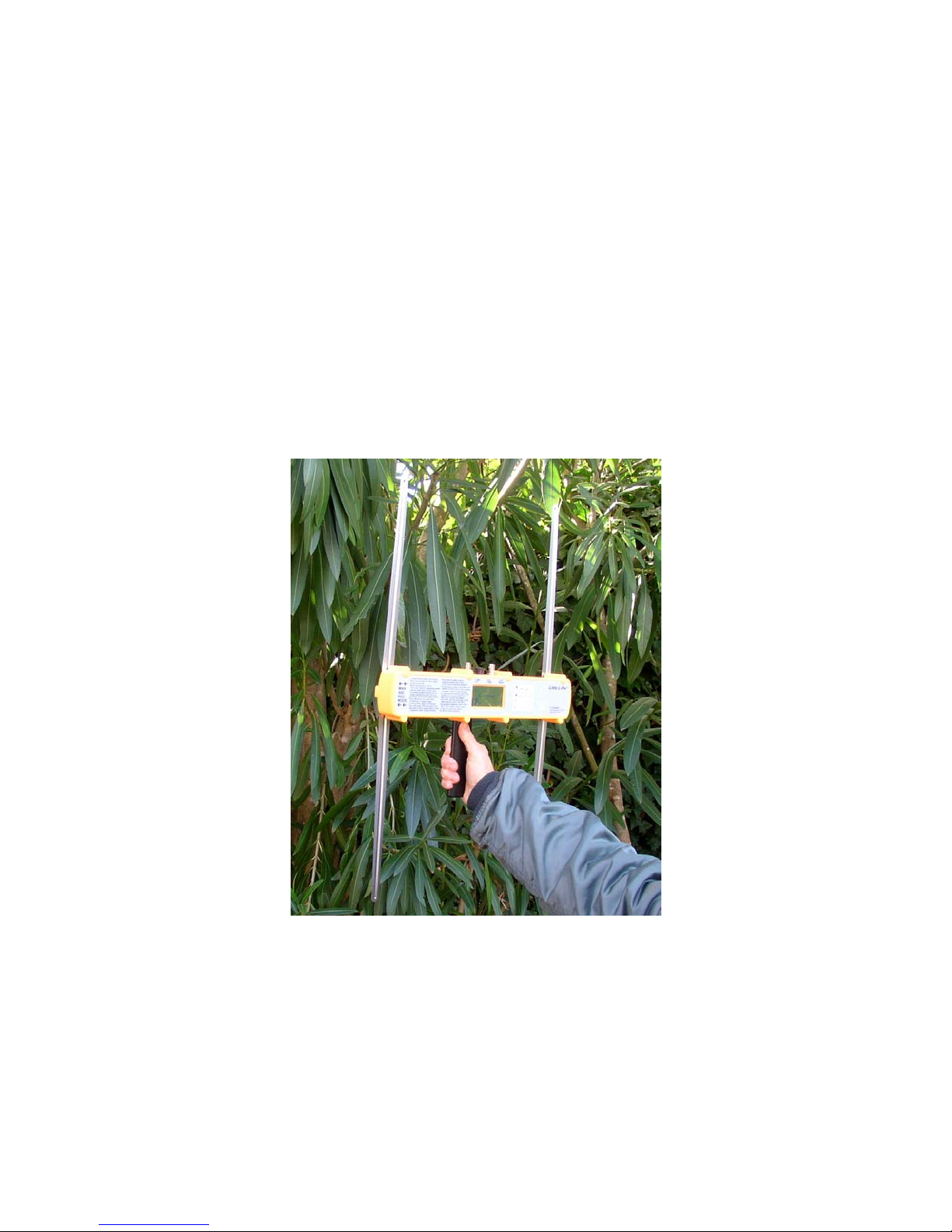
4. Hold the DF with the body clear of the
antennas in the operating position as
shown in Figure 2 and try again.
5. Fold and unfold antennas to clean the
joints.
6. Check the battery indicator. Replace
batteries if no bar is showing.
7. The receiver may not calibrate prop-
erly above 162 MHz on units with
software revisions below 1.71 unless
they have been upgraded
8. It may be too hot or cold. Tempera-
ture limits are -10 to +140°F (-24 to
60°C).
9. The DF may have failed. Contact the
factory for repair.
Changing Frequency
The receiving frequency may be
changed either by direct entry of the desired
frequency or up or down in 100 Hz steps.
To change frequency, first, press the “F”
key and the press “FREQ.” If the “FREQ”
key is not pressed within five seconds, the
“F” or alternate function condition resets. If
this happens, push “F” and then “FREQ”
again. While in the frequency setting mode,
the letters “FR” appear along the left edge
of the display. Press “F” to end frequency
entry.
To tune in a signal better, to discriminate
against interference, or otherwise change
the frequency in small steps, press the up or
down arrow key. A short press will move by
one step; holding the key down will cause
the frequency to move up or down continu-
ously. Any frequency, whether from opera-
tor entry or from permanent memory, can be
changed this way. The changes will be kept
when the DF is turned off and back on again
but they will not affect the values stored in
memory. Changing frequency in this way
does NOT require a new calibration. For
example, 121.5000 MHz loaded from mem-
ory 1 could be changed with the arrows to
121.5053 and stay there even if the DF was
turned off and on. Pressing 1 again would
return to 121.5000.
A new frequency can be entered directly
by pressing “F” then “FREQ” and the de-
sired frequency on the number keys. Only
the significant digits need be entered and
the decimal point is automatic. Any missing
digits will be set to 0. Press “F” again to
complete the entry. If the new frequency is
out of range, “RANGE” will be displayed
briefly and the old frequency will remain un-
changed. For example: the sequence “F, 1,
3, 6, 2, F” would result in a frequency of
136.2000 MHz. “F, 2, 6, F” would cause a
“RANGE” error and retain the old frequency.
CAL is required when a new frequency is
entered this way.
Note that once an arrow key is pressed,
direct entry is disabled and once entry is
started, the arrows are disabled. If a mis

9
take is made, just press “F” to quit and then
“F” and “FREQ” again to start over.
Storing a frequency
After a new frequency is entered, it will
be labeled as “NEW” on the display. There
is no provision for custom labels. This new
frequency will be retained if the power is
turned off and back on but will be lost if any
other memory is loaded. To store this fre-
quency for later use, press “F” then
“STORE”. The letters “ST” will appear on
the left edge of the display. Select a mem-
ory number for storage of this new fre-
quency and press a number from 5 to 0.
The old data, if any, in that memory location
will be erased. The “NEW” label will be re-
placed by the memory number when this
entry is later recalled. An attempt to store to
a permanent memory location (positions 1
through 4) will be rejected.
USING EXTERNAL ANTENNAS
Two BNC jacks are located on the top of
the DF for connecting external antennas.
When set for AUTOmatic operation, any
antenna with a DC resistance of 500 ohms
or less at its connector will be detected by
the DF when it is plugged in. The DF will
shut off its internal antennas and work from
the external one(s). It will return to using its
internal antennas when the external anten-
nas are disconnected. See also section on
Calibration.
The L-Tronics®magnetic, flexible, air-
craft, and LH Series L-Per®handheld an-
tennas will all be detected. Adding a 470
ohm resistor to the L-Tronics®LHBM-1
beam and LVA-1 monitor antennas will al-
low automatic detection of them, plugged
into either jack.
NEVER apply power or more than 10
mW RF or any DC voltage to these jacks.
External antennas can also be selected
manually (see “Other Adjustable Values”
below). The jack that the external antenna is
plugged in to sets whether the DF displays
the data left and right (left/right jack) or up
and down (fore/aft jack). Plugging two an-
tennas at once will switch to the FALR
(Fore/Aft-Left/Right) display.
There are two potential hazards associ-
ated with external antennas:
1. External antennas usually cover only
a narrow frequency range. Beyond
their designed frequency, they can be
wildly erroneous.
2. The DF will not use its internal anten-
nas unless it is set to AUTO (SET1).
Be careful with external antennas to be
sure they are used within their limits. For
example, our magnetic and aircraft anten-
nas have a range of only 118 to 126 MHz
and 235 to 260 MHz.
OTHER ADJUSTABLE VALUES
Several other settings are selectable be-
side frequency, DF mode and volume.
These are controlled through setup screens
“SET1,” ”SET2,” and “SET3.” “SET3” con-
tains only the model number, frequencies,
and revision numbers.
To work with the SET menus, press “F”
and then “SET1,” “SET2” or “SET3.” One or
more items on a menu can be changed in a
single session by selecting its item number.
Except for contrast, these selections are
retained in the individual frequency memo-
ries. To end the session, press “F” again.
SET1 + KEY PAD ENTRY NUMBERS
1. Pressing this number alternately se-
lects FM or AM audio detection. This selec-
tion affects only what is heard on the
speaker. It does not affect DF operation.
The default is AM below 137 MHz and
above 235 MHz and FM elsewhere.
2. Pressing this number selects “AUTO,”
“F/A,” “L/R,” and “FALR” antenna switching.
The default for permanent memories is
“AUTO.” The other choices allow for manual
selection when using external antennas that
do not give sensing for automatic selection.
This MUST BE SET to AUTO for the built-in
antennas to work.
3. Press 3 and then use the up and
down arrows to adjust the display contrast.
If the display is too light to read, hold the UP
arrow and, if it is all black, hold the DOWN
arrow until the display appears. Contrast is
stored in a common memory so the last

10
adjustment made applies to all frequency
memories.
4. Pressing this number selects “FAST,”
“MEDIUM,” and “SLOW” display filters.
“MEDIUM” is the default and is usually best
for hand-held operation. “FAST” is best for
catching short, pulsed signals. "MEDIUM"
and “SLOW” can reduce the flutter caused
by nearby objects while driving or for de-
tecting very weak signals.
5. ELT signals are usually strings of
pulses sent at a varying rate to give the
warble sound. The transmitter is usually on
only 1/3 of the time to give better battery
life. Peak detection gives better perform-
ance on these signals and is the default for
the programmed ELT frequencies. It may
give an erroneous left or right indication with
no signal on some frequencies. For com-
munication signals, turn peak detection off.
6. Display gain allows reducing the sen-
sitivity of the DF indications when larger
external antennas are used. The default is
“high.” It may be set to the operator's taste.
7. Turns the BFO ON or OFF if this op-
tion is available. The change occurs when
leaving the menu.
It is common to use different default set-
tings for mobile and walking. Preferred set-
ups can be stored in some of the user
memories to be recalled when needed with-
out having to reprogram each time. It is
better to store a setting with the dial lights
off so they aren’t part of the memory and
don’t run the batteries down unnoticed dur-
ing the day.
EXTERNAL POWER AND AUDIO
The 6-pin jack on top of the DF between
the BNC jacks provides for external power
input and audio output. An optional mating
connector with a 4 wire, 6 foot cable is
available from L-Tronics®as part number
120014. The mating connector only is
available from Digi-Key (www.digikey.com)
as p/n HR8560ND (Hirose HR30-6P-6S);
soldering small pins is required. Connec-
tions are:
Pin Color Function
1 Black Ground
2 Red + input power
3 White Audio out
4 Green Reserved
5 Reserved
6 Reserved
To connect the cable, align the white ar-
rows on the connector halves and push on
the back of the plug. To remove, pull on the
ring on the front of the plug, NOT the body.
If it comes apart hard, it is being done im-
properly and it may break.
The input voltage should be between 6
and 28V. Maximum current with lights on
and loud audio is about 250mA. The unit will
withstand up to +80V and –40V without
damage, but will not operate until the volt-
age returns to the working range. The ex-
ternal power input draws about 10mA with
the DF shut off.
The audio output will drive headphones
or a small speaker connected between pins
3 and 1 (white and black). Do not apply
external power to this line. The output level
varies with the DF volume control.
ODDS AND ENDS
Pressing “F” and “LOCK” will partly lock
the keys. When locked, only the “POWER,”
“LIGHT,” “REC/DF” and “LOCK” keys work.
To unlock, press “F” and “LOCK” again.
Starting with software revision 1.71
(shown on the bottom line of SET3) dated
12 October 2006, an Automatic Power Off
(APO) function has been added. The APO
will turn the DF off if no keys are pressed for
either 15 or 60 minutes. This will prevent
discharge of the batteries if an operator for-
gets to turn the DF off or if it is accidentally
turned on. The APO does not shut the DF
off when the external power is plugged in.
The APO may be set to 15 minutes, 60
minutes, or off by using SET2 (F, SET2, 1,
F.) This upgrade can be added at the fac-
tory to earlier units.
The receiver has a few low-level spuri-
ous responses, particularly at multiples of 4
MHz (116, 120, 124 MHz, etc.) that will
cause the DF display to go off center. These
will be over-ridden by all but threshold-level
actual signals.
This DF has a narrow bandwidth loga-
rithmic receiver. This means that older,
wide-band FM communications signals and
AM signals with full modulation will sound

11
distorted. This is not a receiver fault. It also
means that reception of older ELTs, which
have wider frequency tolerances, may be
improved by tuning the DF receiver fre-
quency by a small amount using the UP and
DOWN arrow keys. Careful tuning may also
allow separation of two simultaneous ELTs.
One or two attenuators are switched in to
extend the strength measurement range for
strong signals. They make an audible “ping”
when they change and may cause a jump in
strength numbers. The attenuator dots show
when they are in use (Figure 1).
Occasionally, the LCD display can be-
come confused. If this happens, pressing
the DF/REC key twice or the sequence F,
SET1, F should clear it. Also, the key pad
may not respond properly to rapid key
pushing. Slow and deliberate works best.
The low temperature operating limit is set
by the LCD display, which responds very
slowly when cold. Contrast adjustment
helps somewhat. Slow and deliberate works
best.
The case of the DF is sealed with the
battery plug in place. It is designed to with-
stand water immersion to 10 ft and altitude
to 15,000 ft. With batteries installed, it does
float. If it is moved to a different altitude for
an extended period and the weather is dry,
we suggest opening the battery plug briefly
to equalize pressure. The case seal is not
hermetic; moisture can accumulate inside
as a fog on the display due to “pumping” by
daily temperature changes. If this happens,
or if water gets inside for any other reason,
remove the battery plug and let the case dry
out. The process can be speeded by putting
it in a warm place, but not over 120°F.
The case should have a gap of .010 -
.015 at the seal. DO NOT tighten the case
screws further.
BREAKING THE SECURITY SEALS
AND OPENING THE CASE WILL VOID
THE WARRANTY.
The folding handle is removable to allow
the DF to be mounted another way. The
screw has ¼-20 threads, the same as used
on most camera equipment and tripods.
Take care not to loose the “wavy plates”
that are a part of the index mechanism. L-
Tronics®also has a simple drop-in bracket,
p/n 120013, available to keep the unit in
place in a car or airplane.
The screws holding the built-in antennas
are sealed with Locktite®. Should one ever
work loose, a drop of Locktite®7, preferably
290 grade (green) should be applied to hold
it and to maintain the case seal.
If the battery plug is lost, stuffing crum-
pled aluminum foil into the open hole may
keep the DF running until a new plug is ac-
quired.
Starting with software revision 1.71
(shown on the bottom line of SET3) dated
12 October 2006, a Beat Frequency Oscil-
lator (BFO) function has been added. The
BFO allows unmodulated (carrier only) sig-
nals to be heard and can give a small im-
provement in the ability to hear very weak
ELT signals. Direction can be determined by
turning the DF for the loudest signal in RE-
CEIVE mode, using either the built-in an-
tennas or an external beam antenna. IM-
PORTANT: Listening for changes in audio
volume works only for weak and noisy sig-
nals. For stronger signals, the sound be-
comes constant and strength changes are
indicated by the strength bar and numbers.
The pitch of the BFO sound may be ad-
justed by changing the receive frequency.
Press f, then FR. Use the arrows to tune up
or down and F again to stop tuning. The
frequency will return to its saved value the
next time that memory channel is selected.
This is an advanced technique and should
be practiced and well understood before
being used on an actual search. This up-
grade can be added at the factory to earlier
units with serial numbers above 30197.
MORE ABOUT BATTERIES
First, no matter the type, use fresh, good
quality batteries. Customer reports and our
own experience over many years suggest
far fewer problems with Eveready®and
Duracell®than any other manufacturers.
Saving a dollar only to have a battery jam in
the tube, go dead when needed, or dribble
caustic goo in the works is really foolish. If
possible, buy from a store that sells a lot of
batteries and check the date codes so you
get fresh ones.
The LL Series Direction Finder uses six
1.5V AA size batteries. For normal service,
we recommend alkaline batteries, as these
give the best combination of service life,

12
cost, and resistance to corrosion. New alka-
line batteries will run the DF for about 30
hours. When the bar on the battery indicator
symbol on the front panel display disap-
pears, about one hour of operating time re-
mains.
If long storage life or extended operation
below –10º is needed, use 1.5V Lithium-iron
sulfide batteries (Eveready L91).
NEVER USE 3V LITHIUM BATTERIES.
They will damage the receiver.
Use NiCd or NiMh rechargeable cells
only if your DF is being used an hour or
more per day.
To change batteries, unscrew the battery
plug on the right side of the DF until it is
loose, then gently pull it out. Insert the bat-
teries with the positive (+) end first into the
battery tube. Reseat the plug and push in
gently to engage the threads, then screw
the cap in until the “O” ring is in contact with
the case all the way around.
Alkaline cells have a capacity of about
2600 mAH at 68°F and should give about
30 hours of operation with average volume
settings and panel light use. The DF will op-
erate at full accuracy down to 5.4V from the
battery or 0.9 volts per cell to extract the full
battery energy. Cells lose about 5% of their
energy per year at 68°F, more if hotter and
about 1% if kept in a refrigerator. Only about
45% of the battery energy is available at -
10°F. Battery seals usually last more than 5
years if the cell is not discharged but bat-
teries still should be taken out if the DF will
be stored for a long time. If the batteries do
corrode, get them out if you can and clean
out the mess with a DRY bottle brush.
NEVER use any liquid cleaner as it can leak
into the circuit boards. Battery tubes are
factory replaceable.
Carbon-zinc batteries, strangely often
called “heavy duty,” have a capacity of
about 1500 mAH, have only about 30% of
that at -10°F and have a higher self-
discharge rate than alkaline. These should
be considered only if alkaline batteries are
not available.
Oxyride batteries from Panasonic®are
relatively new at a small price premium, but
are not a good choice for the DF. Their ini-
tial voltage of 1.7V per cell is just safe for
the DF and they have more available en-
ergy than standard alkaline cells for cam-
eras and toys but less at the current drain of
typical of DF operation. Further, the low
temperature performance is poor.
Nickel-Cadmium and Nickel-Metal hy-
dride batteries are a good choice if the DF is
being used often such as for training. NiCd
cells up to 1000mAH and NiMh cells to
about 2000mAH are available. This is fine
as long as they can be readily recharged.
The big problem with these batteries is that
they self-discharge rapidly, particularly at
high temperature, and this leakage usually
gets higher with use, particularly if simple
chargers are used.
The leakage in NiMh batteries can go so
high that your DF can be dead after a few
hours in a closed car in summer. If you do
use these batteries, note that the battery bar
on the screen is set for alkaline batteries
and will not indicate full scale even with a
fully charged battery.
A new type of lithium battery using iron
sulfide came to our attention after the DF
panels were printed. This one is an excep-
tion to the “no lithium” restriction. Currently,
the Eveready®L91 is the only one we know
to be available and costs $2.50 or more
each. These batteries have three advan-
tages: self discharge of 1% per year at 68°F
or 15 year shelf life; better than 80% capac-
ity at -10°F; and about 20% greater energy
than alkaline batteries when used in the DF.
A set of batteries is also about 2 ounces
lighter.

13
DIRECTION FINDING TECHNIQUES
Following is a summary of Direction Finding
Techniques. More information can be obtained
from our publications LHTM-1, “Air and Ground
Direction Finding,” LHTM-2, “Locating Non-
distress ELTs and EPIRBs,” and LHTM-3, “Basic
ELT Location Course.” All techniques used by
the LH Series Little L-Per®Direction Finders is
applicable to the LL Series.
A key to the efficiency of the L-Per® is its
ability to evaluate the quality of the bearings
obtained. Beware of reflections; it is impossible
in a practical sense to obtain bearings from
some locations. The L-Per®will tell you quickly
when this situation exists so a new site can be
selected. Further, bearings of low quality can be
identified and taken into account when conflicts
occur in a triangulation problem.
We strongly recommend that you do initial
practice with the DF in an open, clear area and
then around buildings or other obstructions to
become familiar with its operation with a known
target before trying an unknown. A practice ELT
fitted with a dummy load in place of its regular
antenna will provide weak signal simulation
practice in walking range.
DETERMINING BEARING RELIABILITY
Reliability Circle
In the DF mode, turn in the direction the bar in-
dicates until it nearly disappears or points
equally left and right. You are facing the signal
source. Now slowly turn in a full circle to the
right while holding the DF in the operating posi-
tion and watching the display. The bar should
darken to the left, center at approximately oppo-
site the ELT, darken on the right side, then cen-
ter when you are again facing the signal source.
If the bar centers twice, about 180 degrees
apart, the location is good and the bearing will
be accurate. If it centers more than twice, or
twice but less than 120 degrees apart, it is not a
good location and bearings won’t be accurate.
Choose a better location for DF.
Walking a Baseline
After performing the reliability check as de-
scribed above and finding a good location,
check for the existence and severity of reflec-
tions. You might, by good luck, have chosen a
spot that may initially shows good bearing reli-
ability but is really not.
In the DF mode, center the bar and walk a
straight line for 10 to 20 feet WHILE CON-
TINUOUSLY OBSERVING THE INDICATED
DIRECTION. If no significant reflections are pre-
sent, the indicated direction will remain steady to
within five degrees.
As reflected signals become prominent, the
indicated direction will oscillate back and forth
every four or five feet. A good estimate of the
true direction of the signal can be made by tak-
ing an “eyeball average” of these variations
while walking a baseline of up to 50 feet. Fluc-
tuations of more than 60 degrees each direction
indicates a very poor DF site.
RADIO SIGNAL PROPAGATION
There are three characteristics of any radio
signal that MUST be understood to locate the
transmitter. They are:
1. Unimpeded, radio signals travel in a straight
line. This principle is responsible for satel-
lites being able to hear an ELT even though
objects on the ground prevent it from being
heard there.
2. Signals get stronger near the source. The
further away from the signal source, the
weaker the signal is if it isn’t blocked. In ad-
dition, the RATE OF CHANGE in signal
strength is faster as you get closer. Different
conditions can influence absolute signal
strength but usually don’t affect the rate of
change. This makes rate of change a more
reliable indication of how close you are to
the transmitter than any given strength
reading.
3. Conductive objects reflect and/or block the
signal. These include metal structures,
stucco buildings (chicken-wire mesh), con-
crete buildings (steel reinforcing bars), chain
link fences, buildings with metalized glass
sunscreens, mountains, smooth snowfields,
and grasslands. These objects are called
“reflectors” because they cause the trans-
mitter’s signal to bounce off, much the same
way a mirror reflects images.
All DF techniques will come back to one or
more of these principles.

14
REFLECTORS
Reflections cause almost off of the problems
in transmitter (ELT and EPIRB) location.
Solid conductive objects, like metal buildings
and mountains, both reflect and block the signal.
Non-solid objects like fences will reflect some of
the signal and allow most of it to pass through.
Non-conductive objects act much the same way
as the metal fence. The L-Per®’s response de-
pends on the reflector’s location. You’ll have
different results with a reflector near the trans-
mitter, one near the receiver, and one between
the ELT and the L-Per®.
Reflectors Near The Transmitter
A reflector near the transmitter can affect
your ability to hear the signal, but usually causes
no problem in tracking once the signal direct
from the transmitter can be heard.
If the ELT is next to a metal building, most of
the signal will reflect or “bounce off” the building
rather than go through it. The signal will be diffi-
cult to hear and track when you are in a location
that places the building between you and the
ELT. If you can hear the ELT, the L-Per®will
give good directional information because both
the direct and reflected signal are coming from
the same direction.
Reflectors Near The Receiver
A reflector near the receiver can cause se-
vere problems for the L-Per®, but once recog-
nized, can usually be avoided.
A reflector within about 200 feet of the L-Per®
will cause it to see both the direct and reflected
signal, but each will be from a different direction.
However, the signal direct from the ELT will be
stronger than a reflected signal and the L-Per®
will prefer the stronger, direct one.
Reflected signals always lose power. They
will be weaker than the direct signal from the
ELT if – and this is the biggest if – nothing is
blocking the direct signal.
Blocked Signal, Single Reflector
Reflections are not much of a problem in ELT
location UNLESS the direct signal from the ELT
is blocked. When blockage occurs, the direction
finder will “see” all of the reflections, which will
vary in strength and direction.
In some cases where the signal is blocked,
the solution to the problem is rather straightfor-
ward. If the L-Per®hears a reflected signal from
only one direction, it will track the reflection until
it can hear the direct signal. Once it does, direc-
tion to the ELT will be obvious and it will give
you a heading to the stronger, direct signal.
Blocked Signal, Multiple Reflectors
Multiple reflections coming from the same
general direction when the direct signal is
blocked will cause much the same results as a
single reflector. The L-Per®will follow the reflec-
tions until it hears the stronger, direct signal then
will track the ELT.
As you walk while tracking the reflections,
you may notice the apparent direction swings
back and forth, but you’ll be walking a line that
represents an average of the directions to the
reflections.
Resolving Multiple Reflections
If your initial bearings on an airport ramp look
like you will be working among multiple reflec-
tions, such as a group of hangars, you should
expect the L-Per®to have difficulty averaging
directional information when among the build-
ings. There are a couple of ways to recognize
and deal with this problem.
To evaluate the severity of reflections, make
a 360-degree reliability turn while observing the
DF display. If you get multiple centerings as you
turn, you are in an area of reflectors. Next, walk
15 or 20 feet and keep the bar centered by
moving the receiver back and forth. Take a step,
swing the receiver to center the display, take
another step, center the bar, take another step,
center, etc. If you have to swing the receiver in
an arc of more than 120 degrees, you have re-
flections coming from all directions and the DF
will not be usable.
If your swings are less than 120 degrees, you
can continue walking in a direction that is an
average of the headings of the swings. This is
not a precise method of DFing, but it will keep
you moving in the right direction.
When reflections are coming from many di-
rections or all sides of the L-Per®, the combined
directional information will be very confusing to
it. The best procedure is to get out of the area.
Move 200 feet or more away from the reflectors
and walk completely around them if possible.
The L-Per®will give good directional information
from all sides, even though the direct signal may
be blocked from certain angles. This will give
you a clearer picture of the area of highest prob-
ability before you have to search among the
buildings. You can often isolate a single suspect
building from this “standoff” position.
Now you will have a better idea of where to
start your close-in search. DF mode may not
work in this area; if it doesn’t, use the “build and
fade” method using the strength indications.
Direction Finding Inside a Building

15
Direction indications is often not useful inside
a building because of so many reflections near
the receiver. If there are a number of aircraft
inside, it is often faster to rely only on strength
readings. Strength response is not directional in
DF mode. Use DF mode while walking about a
hanger or rooms in a building, looking for
changes in strength reading. The Model LL L-
Per®has enough strength range that offset tun-
ing or external small antennas are unnecessary.
As you walk around the building, watch the
strength reading. Continue walking in the direc-
tion that causes the strength to increase. Ignore
small variations of strength five to 10 feet apart.
While you walk, look around for the ELT or a
location where it might be, such as a table,
locker, flight bag, etc.
Using the L-Per®in the Fore/Aft Mode
When reflections are a real problem, such as
among metal buildings or in harbors, you can
use the L-Per®in the Fore/Aft mode, just as you
would on a vehicle.
Select the DF mode and then, instead of ho
Holding the unit in front of you at eye level,
hold it off your right shoulder so you have to turn
your head to the right to see the display. The left
end of the DF (with the arrows) is facing forward.
As you walk holding the receiver in this position,
watch the left-right bar and keep the bar pointing
to the left side. As long as the bar is on the left
side of center, you are walking toward the signal
source. If the bar is on the right side of center,
you are walking away from the ELT.
Horizontal Polarization
The LL Series Direction Finder works best
with transmitters that have vertically polarized
antennas. The most accurate bearings are ob-
tained when the antennas on the transmitter and
receiver are the same polarization. If the ELT is
lying on its side and transmitting a signal that is
horizontally polarized, the result can act as a
barrier in the direct path and emphasize the re-
flections.
If holding the L-Per®horizontally overhead
shows a strength increase of 20 counts or more,
the signal is horizontally polarized. While not
convenient, the L-Per®can be held overhead in
a horizontal position and worked in the “fore/aft”
mode as just described.
Table of contents
Popular Measuring Instrument manuals by other brands

Coaxial Dynamics
Coaxial Dynamics Web Wattchman instruction manual

Sonotec
Sonotec SONAPHONE RD operating manual

XS Instruments
XS Instruments Temp70 PT100 vio instruction manual

Honeywell
Honeywell DR Graphic Installation instruction

Rotem
Rotem RAM GENE-1 operating manual

Stoneridge
Stoneridge SE5000 quick guide