Lütze LOCC-Box-GWPN 0-6457 User manual

Automation solutions
Operating Instructions
EtherCAT-Gateway 716456
Description of EtherCAT-Gateway in combination with
LOCC-Box-Net 716410 and 716411.
Version 1.1

Operating Instructions EtherCAT-Gateway
2 Ethercat-Gateway 716456_110_HB_EN.Docx
This Operating Instruction is an integral part of the device and contains important information about
safety and how to operate the unit. Before using the unit, carefully read this Operating Instruction in
order to rule out possible dangers and damage, and to guarantee correct use.
This document and the information contained herein were prepared with reasonable diligence. even
so, Lütze does not assume any responsibility for printing errors or other, or
damages originated by them.
The trademarks and product names mentioned in this book are subject to absolute
provisions of the effective label right and property rights of the respective registered owners.
Copyright 2013 by Friedrich Lütze GmbH. All rights reserved.
How to reach us
Friedrich Lütze GmbH
P.O. Box 1224
D-71366 Weinstadt - Großheppach
Germany
Phone - reception: +49/ (0)7151/ 6053-0
Fax: +49/ (0)7151/ 6053-277
Internet: http://www.luetze.com

Operating Instructions EtherCAT-Gateway
Ethercat-Gateway 716456_110_HB_EN.Docx 3
Table of contents
1General information.....................................................................5
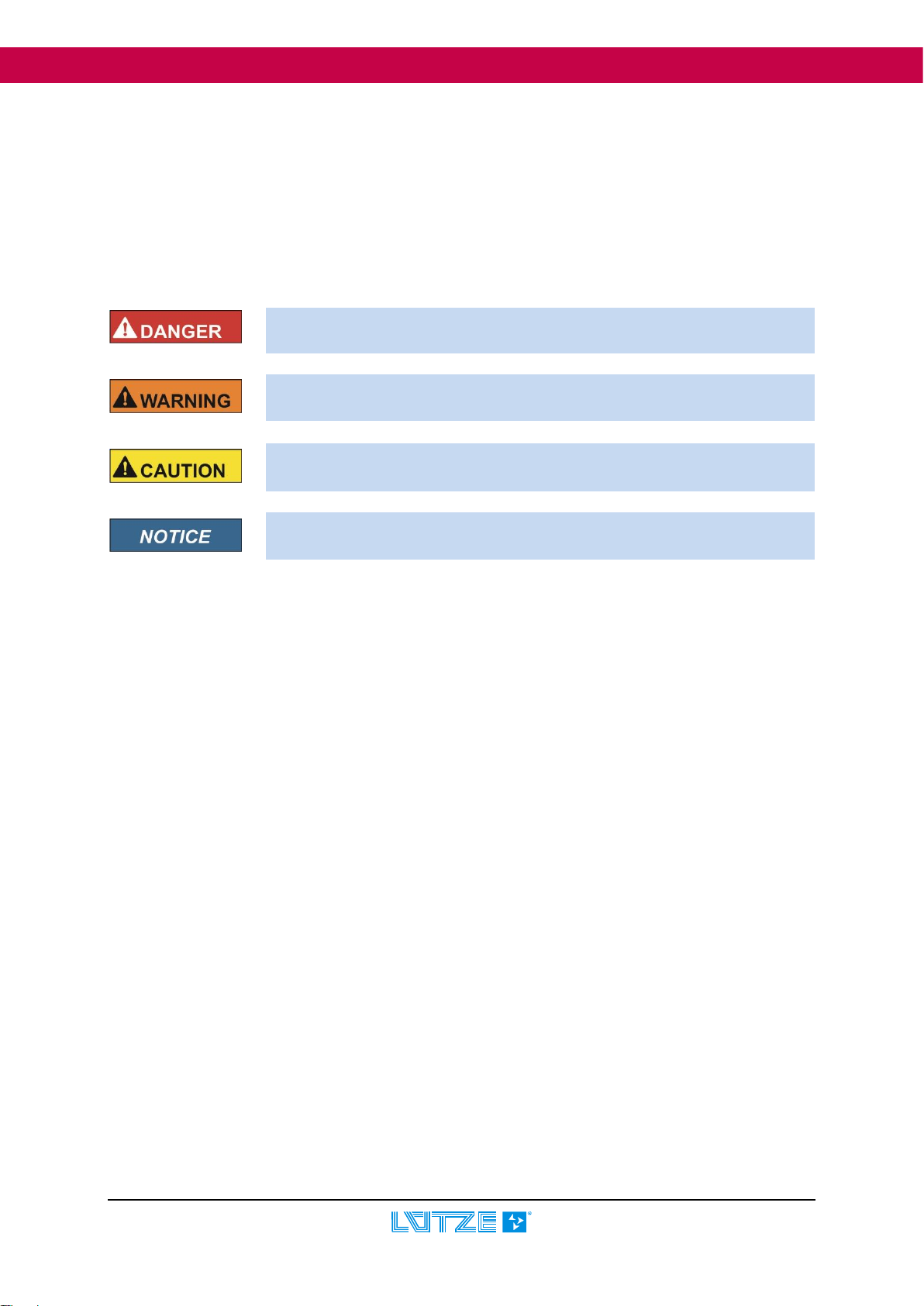
1.1 Explanation of symbols.....................................................................................5
1.2 Copyright...........................................................................................................5
1.3 DISCLAIMER....................................................................................................5
1.4 Safety Instructions ............................................................................................6
1.4.1 Content of the Operating Instruction...................................................................................6
1.4.2 Appropriate Use..................................................................................................................6
1.4.3 Operating staff ....................................................................................................................6
1.4.4 Maintenance .......................................................................................................................6
1.4.5 Shutdown and disposal.......................................................................................................6
2Gateway –EtherCAT, 716456......................................................7
2.1 General.............................................................................................................7
2.1.1 Explanation.........................................................................................................................7
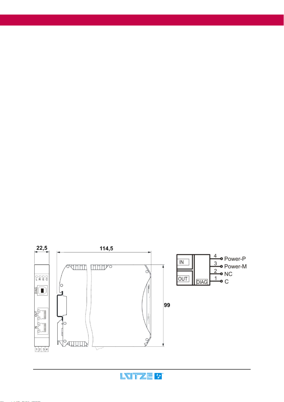
2.1.2 Dimensions and connections..............................................................................................7
2.1.3 Function and displays.........................................................................................................8
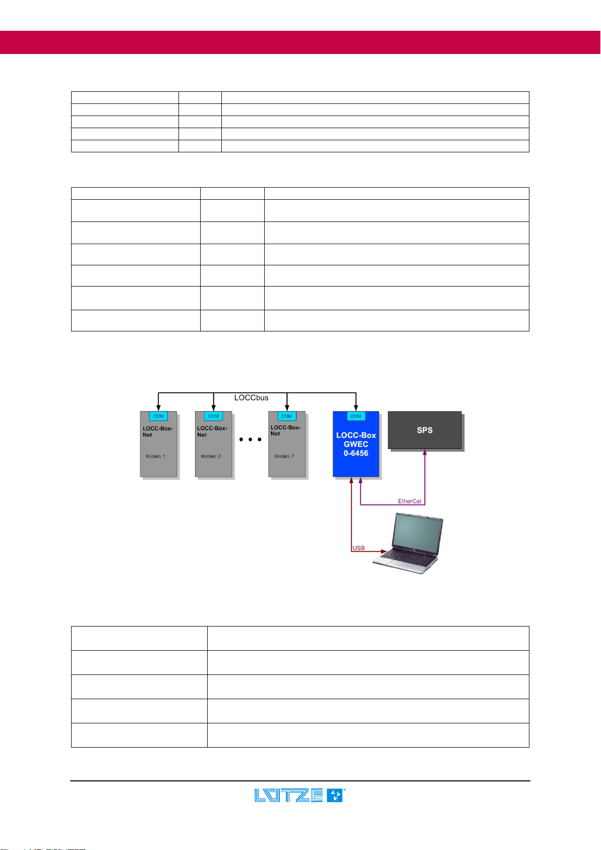
2.1.4 Topology and design ..........................................................................................................8
2.1.5 LOCCbus - interface...........................................................................................................8
2.1.6 Operating system, interface................................................................................................9
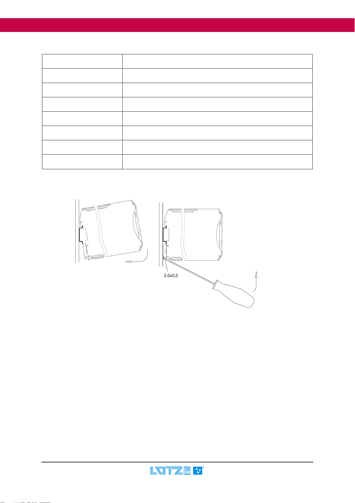
2.1.7 Mounting.............................................................................................................................9
2.2 Installation.......................................................................................................10
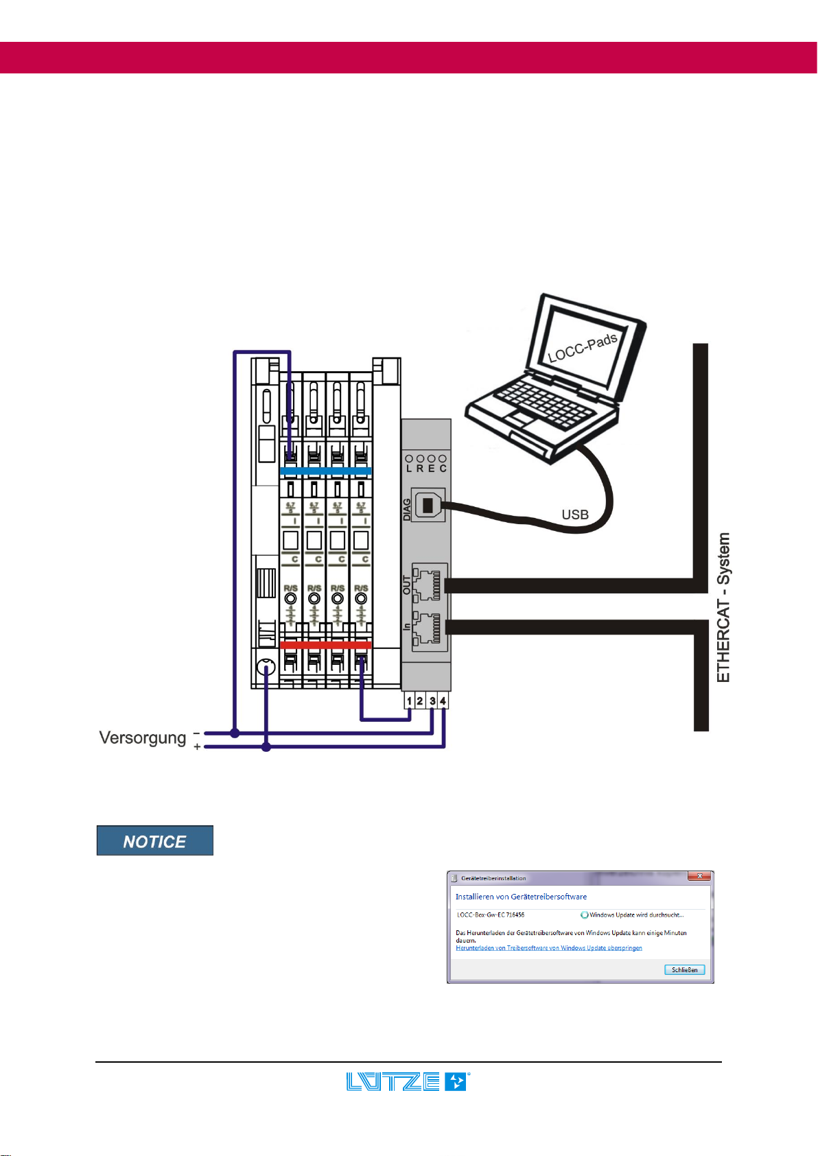
2.2.1 Principle design.................................................................................................................10
2.2.2 Connection to USB ...........................................................................................................10
2.3 Communication with LOCC-Pads ...................................................................10
2.4 Communication with EtherCAT.......................................................................11
2.4.1 Terms................................................................................................................................11
2.4.2 Description file ..................................................................................................................12
2.4.3 EtherCAT interface ...........................................................................................................12
2.4.4 Overview LOCC-Box-Net module.....................................................................................12
2.4.5 Communication Profile Area.............................................................................................12
2.4.6 Manufacturer Specific Area ..............................................................................................13
2.4.7 Standardized Profile Area.................................................................................................14
2.4.8 Alarm, emergency.............................................................................................................14
2.4.9 Process image..................................................................................................................15
2.4.10 Examples of the indexes used......................................................................................15
2.4.10.1 Device type (1000h)................................................................................................15
2.4.10.2 Device name (1008h) .............................................................................................15
2.4.10.3 Hardware version (1009h)......................................................................................16
2.4.10.4 Software version (100Ah).......................................................................................16
2.4.10.5 Identity (1018h).......................................................................................................16
2.4.10.6 Module type (2000h)...............................................................................................16
2.4.10.7 Module state (2010h)..............................................................................................17
2.4.10.8 Module configuration (2011h).................................................................................17
2.4.10.9 Output voltage (2100h)...........................................................................................18
2.4.10.10 Input voltage (2101h)............................................................................................18
2.4.10.11 Current measurement (2104h) .............................................................................18
2.4.10.12 Characteristic curve setting (210Ah) ....................................................................19

Operating Instructions EtherCAT-Gateway
4 Ethercat-Gateway 716456_110_HB_EN.Docx
2.4.10.13 Software version (2200h)......................................................................................19
2.4.10.14 Serial number (2201h):.........................................................................................20
2.4.10.15 LOCC-Box counter 'Operating voltage ON' (2202h) ............................................20
2.4.10.16 LOCC-Box counter 'Operating hours (h)' (2203h)................................................20
2.4.10.17 LOCC-Box counter 'Operating hours ON (h)' (2204h)..........................................20
2.4.10.18 LOCC-Box counter 'Triggered' (2205h)................................................................21
2.4.10.19 LOCC-Box counter 'Activation' (2206h)................................................................21
2.4.10.20 LOCC-Box settings (2208h)..................................................................................22
2.4.10.21 Setting current range, (I) (2209h) .......................................................................................23
2.4.10.22 Setting characteristics, (C) (220Ah)......................................................................23
2.4.10.23 Cycle time of the query in ms (2400h)..................................................................23
2.4.10.24 Reset and automatic issue of the node number (2800h) .....................................23
2.4.10.25 Query 'Status node number' (2801h)....................................................................23
2.4.10.26 Reset and Operating Instruction issue of the node number (2802h) ...................24
2.4.10.27 Identification - 'Hallo function' (2808h)..................................................................25
2.4.10.28 Module status ON / OFF (6000h) .......................................................................................26
2.5 Technical specifications..................................................................................27
3Replacement LOCC-Box-Net without LOCC-Pads...................28
4Firmware update ........................................................................29
4.1 Introduction.....................................................................................................29
4.2 Download........................................................................................................29
4.3 Installation.......................................................................................................29
4.4 Update ............................................................................................................29
4.5 Install new hardware.......................................................................................31
5Accessories for the LOCC-Box system....................................32

Operating Instructions EtherCAT-Gateway
Ethercat-Gateway 716456_110_HB_EN.Docx 5
1 General information
1.1 Explanation of symbols
The operating instructions contain safety information, which is characterized by a signal word in
combination with a certain colour. The combination stands for the respective warning level. The
information highlights possible dangers and gives instructions on how to avoid them.
1.2 Copyright
The Operating Instruction is intended for the operator and its staff only. The content may not be
passed on in full or in part to third parties, reproduced, recycled or otherwise to the extent that this has
not been writing permitted by Lütze Transportation GmbH. It is forbidden to give the contents to a third
party, to duplicate, exploit or otherwise disclose these in part of in full unless authorized expressly and
in writing by Friedrich Lütze GmbH. Details, texts, images and drawings in the contents are copyright
protected and are subject to commercial property rights. Contravention can be prosecuting criminally.
The trademarks and product names mentioned in this document are subject to absolute provisions of
the effective label right and property rights of the respective registered owners.
1.3 DISCLAIMER
The content of the Operating Instruction was checked in accordance to the described hard- and
software. The content is verified of accuracy. Discrepancies are not excluded. For those
discrepancies we disclaim liability. The content of the Operating Instruction is checked frequently.
Applicable changes and additional information
will be in the next version of the Operating Instruction.We highly appreciate improvement suggestions.
The company Friedrich Lütze GmbH does not accept any responsibility for damages caused by the
ignorance or deficient knowledge of the Operating Instruction. For this reason it is advisable that
the operator asks the staff to confirm with their signature that they have received the instructions.
For reasons of safety no changes or modifications may be made to the modules. Therefore, any
modification of the modules which is not specifically allowed by the manufacturer will cause the loss of
all claims for damages against
Friedrich Lütze GmbH. The same applies to the use of non-original or not authorized parts or
equipment.
Indicates a dangerous situation, which can lead to death or serious injuries
if not observed.
Indicates a dangerous situation, which can lead to slight or moderate injuries if
not observed.
Indicates a situation, which could damage the product or the environment
. This information foresees injuries.
Indicates a dangerous situation, which can lead to death or serious injuries
if not observed.

Operating Instructions EtherCAT-Gateway
6 Ethercat-Gateway 716456_110_HB_EN.Docx
1.4 Safety Instructions
1.4.1 Content of the Operating Instruction
The Operating Instruction must be read before starting to work on or with the device and observed
accordingly. This applies to all persons who come into contact with the device. Trained personnel and
specialists, in particular electricians, who have already worked with similar devices must also read and
understand these instructions.
1.4.2 Appropriate Use
The devices are only designed for industrial use. Appropriate use includes following the instructions in
the operation Operating Instruction. The units may only be used for the cases described in the
technical documentation and
together with units and components from the producers recommended and authorized by us. A correct
and safe operation of the product requires an appropriate transport, proper storage,
installation and mounting as well as a careful handling and maintenance.
1.4.3 Operating staff
The following work on the modules may only be carried out by qualified staff:
•Installation
•Initial operation
•Operation
•Maintenance.
Within the meaning of the safety notes, qualified staff refers to people that are authorized to put into
service, connect to earth and label units, systems and electric circuits according to the generally
recognized codes of safety engineering. Operators have to be instructed and trained properly.
1.4.4 Maintenance
The modules themselves are maintenance-free. Therefore, no inspection and maintenance intervals
are required for ongoing operation.
1.4.5 Shutdown and disposal
For the decommissioning and disposal of the modules, the operating company must observe the
environmental guidelines applicable to location of respective country.

Operating Instructions EtherCAT-Gateway
Ethercat-Gateway 716456_110_HB_EN.Docx 7
2 Gateway –EtherCAT, 716456
The LOCC-Box-Net Interface (Gateway) is an electronic component used to distribute and implement
the data and messages of the serial LOCC-Box-Net interface (LOCCbus) to 2 further communication
interfaces such as USB and EtherCat.
2.1 General
2.1.1 Explanation
The serial LOCC-Box-Net interface is a 1-wire communication interface. The physical-electrical
interface of the LOCC-Box is designed in compliance with the LIN specification. The protocol on this
interface is based on the multidrop protocol.
The gateway supports the following interfaces:
➢Full-Speed USB interface with a maximum bitrate of 12 MBit/s acc. to USB 2.0
➢EtherCAT interface IN and OUT. Ethernet 100Base/T is used as a physical transfer layer.
The USB interface (DIAG) is suitable for connection to a standard PC or a notebook. The USB
interface is detected by the operating system as a serial COM interface. Together with the software
LOCC-Pads it serves as an interface for commissioning, configuration and troubleshooting of the
LOCC-Box-Net components and/or for updating the gateway.
The EtherCAT interface with IN and OUT is suitable for connection to e.g. programmable logic
controllers (PLCs) by various manufacturers. The communication relationship of the 2 gateway
interfaces, USB and EtherCAT, are each exclusively designed for the LIN interface of the LOCC-Box-
Net interface. No cross communication (USB <-> EtherCAT) among each other is planned.
Simultaneous communication of the USB and EtherCat is possible.
The LIN interface and the power supply of the LIN interface and the gateway (P and M) themselves
are attached via the 4 terminals of the casing. The USB interface is a USB-B slot on the front side of
the casing like the two EtherCAT-RJ45 slots.
2.1.2 Dimensions and connections
1 C: 1 Wire bus, LOCC-Box-Net
2: NC: not contacted
3: Power-M: Supply 0V
4: Power-P: Supply DC12/24V
DIAG:USB slot
IN: Connection “IN“
OUT: Connection “OUT“

Operating Instructions EtherCAT-Gateway
8 Ethercat-Gateway 716456_110_HB_EN.Docx
2.1.3 Function and displays
Function
PIN
Description
C
1
Communication connection, 1 wire bus, LOCCbus
NC
2
not contacted
Power-M
3
0V - Connection for the internal supply of the gateway
Power-P
4
DC 12/24V - Connection for the internal supply of the gateway
Connection: Cage clamps, plugs
Displays
Function
Description
LED L, red - shining
Error
EEPROM error, EEPROM not charged
LED R, green - shining
EtherCAT
ECT Run
LED E, green - shining
EtherCAT
ECT Error
LED C green - flashing
LOCCbus
Data traffic with LOCC-Box-Net modules
RJ-45 LED green
Link/Activity
100Base/T-connection, flashes when there is EtherCAT-
traffic
RJ-45 LED green
Connect
Speed-LED, 100Base/T-connection
2.1.4 Topology and design
2.1.5 LOCCbus - interface
Number
1
Control, controller
UART integrated in the CPU
Bit rate
9600 Baud, 9 Bit, No Parity, 1 Stop-Bit
Physical interface
LIN
Software
In firmware

Operating Instructions EtherCAT-Gateway
Ethercat-Gateway 716456_110_HB_EN.Docx 9
2.1.6 Operating system, interface
CPU
STM32F103C8T6
Operating System
Free-RTOS
Driver
ESD EtherCAT Slave Stack
Firmware update
via USB with configuration program LOCC-PADS
Type
EtherCAT Slave
Controller
Beckhoff ET1100
Galvanic isolation
Transmitter
Description
IN and OUT, RJ45 female connector with LED status display
2.1.7 Mounting

Operating Instructions EtherCAT-Gateway
10 Ethercat-Gateway 716456_110_HB_EN.Docx
2.2 Installation
2.2.1 Principle design
1. Supply the gateway and all LOCC-Box-Net modules with DC 12/24V operating voltage.
2. Connect all “COM“ connections of the modules with the “C“ connection (Pin1) of the gateway. The
jumper combs stated in the accessories are suitable for this. See section 5 Accessories.
3. Connect the gateway using the USB slot of your PC to connect to the Windows software LOCC-
Pads or connect the field bus cable to the connection IN.
2.2.2 Connection to USB
Install the latest version of LOCC-Pads! Here the device driver is copied into
the Windows system directory.
Connect the gateway to the PC / laptop using the
supplied USB cable.
When connected for the first time, the gateway is
recognized as new hardware “LOCC-Box-GW-EC
716456“ and installed automatically.
Please read chapter 4.5 for Operating Instruction
installation.
2.3 Communication with LOCC-

Operating Instructions EtherCAT-Gateway
Ethercat-Gateway 716456_110_HB_EN.Docx 11
Pads
See Operating Instruction 'LOCC-Box-Net_x.xx_HB_DE'
2.4 Communication with EtherCAT
EtherCAT follows the Ethernet standard (acc. to IEEE 802.3) to 100%, works in full duplex and
supports the industrial Ethernet with a transfer rate of 100 Mbit/s (Fast Ethernet).
The device satisfies the EtherCAT standards ETG.1000x S ( R ) V1.0.2 with x = 2..6, ETG.1300 S ( R
) V1.0.3 and ETG.2000 S ( R ) V1.0.2
EtherCAT is IEC, ISO and SEMI standard: (IEC 61158, IEC 61784, ISO 15745, SEMI E54.20)
2.4.1 Terms
CoE CAN application protocol over EtherCAT (Former: “CANopen over EtherCAT”)
DC Distributed Clock
EEPROM Electrically Erasable Programmable Read Only Memory
ENI EtherCAT Network Information Contains configuration information for
on EtherCAT master
EoE Ethernet over EtherCAT
ESC EtherCAT Slave Controller
ESI EtherCAT Slave Information Contains information about EtherCAT
slave devices
ETG EtherCAT Technology Group Homepage: www.ethercat.org
FMMU Field bus Memory Management Unit
HexBin Hexadecimal Binary Used to display data in hexadecimal
notation, e.g. decimal 43707 = 0xAABB
= HexBin: “BB AA” (littleendian)
Init EtherCAT device state “Init”
IP “Init” → “PreOp” State transition from “Init” to “PreOp”
LCID Locale Identifier A number that describes a
language/culture setting
MAC Media Access Control
MBox Mailbox EtherCAT slave device Mailbox
NIC Network Interface Card Also used synonymic to “Network
Interface”
NOP No Operation keine Ausführung
Op EtherCAT device state “Operational”
PDI Process Data Interface
PDO Process Data Object

Operating Instructions EtherCAT-Gateway
12 Ethercat-Gateway 716456_110_HB_EN.Docx
PDU Protocol Data Unit
PreOp EtherCAT device state “Pre-Operational”
SafeOp EtherCAT device state “Safe-Operational”
SM SyncMan, Synchronization Manager
UDINT unsigned double word integer (4 Byte)
UINT unsigned integer (2 Byte)
USINT unsigned short integer (1 Byte)
USB Universal Serial Bus
WKC Working Counter Data field within an EtherCAT PDU
used for error detection, see
ETG.1000 documents for details
2.4.2 Description file
The ESI file that is to be used (EtherCAT Slave Information) is in the LOCC-Pads_x.x.x.x.zip file,
which is available as a free download on the Lütze website.
2.4.3 EtherCAT interface
The gateway acts as a slave with max. 64 possible modules in the EtherCAT system .
Module = LOCC-Box-Net.
2.4.4 Overview LOCC-Box-Net module
Part-No.
Name
Type
Setting:
Current range/characteristics
Parameterisation
Characteristics
716410
LOCC-Box-Net
1
Rotary switch
LOCC-Pads
716410.0050
LOCC-Box-Net
1
Rotary switch
LOCC-Pads
716411
LOCC-Box-Net
3
Software
LOCC-pads, EtherCAT
2.4.5 Communication Profile Area
index
Sub-
Index
Name
Data
type
R/W
Type 1
Type 3
Default
Example
chapter
1000h
-
Device type
UDINT
r
00000191h
2.4.10.1
1008h
-
Device name
String
r
LOCC-Box-GWEC
2.4.10.2
1009h
-
Hardware version
String
r
X.Y
2.4.10.3
100Ah
-
Software version
String
r
X.Y
2.4.10.4
1018h
4
Identity
Record
r
-
2.4.10.5
1
Vendor-ID
63Ch
2
Product code, hexadecimal
716456

Operating Instructions EtherCAT-Gateway
Ethercat-Gateway 716456_110_HB_EN.Docx 13
3
Revision number
X.Y
4
Serial number
XYh
1600h
64
RxPDO1
Record
r
-
1A00h
64
TxPDO1
Record
r
-
1C00h
4
SM Type
Array
-
1C12h
1
PDO assignment
Array
r
-
1C13h
1
PDO assignment
Array
r
-
r = just read
2.4.6 Manufacturer Specific Area
index
Sub-
Index
Name
Data
type
R/W
Type 1
Type 3
Example
chapter
2000h
64
Module type of nodes 1 - 64
USINT
r
2.4.10.6
2010h
64
Module state of nodes 1 - 64
USINT
r
2.4.10.7
2011h
64
Module configuration of the rotary switch
UINT
r
2.4.10.8
2100h
64
Output voltage
UINT
r
2.4.10.9
2101h
64
Input voltage
UINT
r
2.4.10.10
2104h
64
Current measurement
UINT
r
2.4.10.11
210Ah
64
Characteristic curve setting
UINT
r
2.4.10.12
2200h
64
Software version
UDINT
r
2.4.10.13
2201h
64
Serial number:
UDINT
r
2.4.10.14
2202h
64
LOCC-Box counter 'Operating voltage ON'
UDINT
r
2.4.10.15
2203h
64
LOCC-Box counter 'Operating hours (h)'
UDINT
r
2.4.10.16
2204h
64
LOCC-Box counter 'Operating hours ON
(h)'
UDINT
r
2.4.10.17
2205h
64
LOCC-Box counter 'Triggered'
UDINT
r
2.4.10.18
2206h
64
LOCC-Box counter 'Activation'
UDINT
r
2.4.10.19
2208h
64
LOCC-Box settings
USINT
r/w
2.4.10.20
2209h
64
Setting
Current range/characteristics
USINT
r
r/w
2.4.10.21
220Ah
64
Setting characteristics, (C)
USINT
r
r/w
2.4.10.22
2400h
64
Cycle time of the query in ms
UINT
r/w
2.4.10.23
2800h
64
Reset and issue of the node number
USINT
w
2.4.10.24
2801h
64
Query 'Status node number'
UINT
r
2.4.10.25
2802h
64
Reset and automatic issue of the node
number
USINT
w
2.4.10.26
2808h
64
Identification - 'Hallo function'
USINT
w
2.4.10.27

Operating Instructions EtherCAT-Gateway
14 Ethercat-Gateway 716456_110_HB_EN.Docx
r = ready only, r/w = read and write, w = write
Sub-Index = Node number of the connected LOCC-Box
2.4.7 Standardized Profile Area
index
Name
Data
type
R/W
Example
chapter
6000h
Module status ON / OFF - Byte-wise
uint 8
r
2.4.10.28
2.4.8 Alarm, emergency
Error message
If a connected LOCC-Box fails during ongoing operations, the LOCC-Box-GWEC sends an
emergency request acc. to ETG.1000.6.S ® V1.0.2, chapter 5.6.4.
In this case the Error Code is = 0xFF00, Error Register = 0x80, Data[0] = Node number of the failed
LOCC-Box, Data[1] = Data[2] = Data[3] = Data[4] = 0.
Example: Failure of LOCC-Box-Net with node number 6
Master: CoE emergency from slave "Slave 1 (LOCC-Box-Gateway)"
received: [Device specific / 0xff00], Error reg. = 0x80, data[] = 06 00 00 00 00
Info (positive acknowledgement by an LOCC-Box-Net)
If this LOCC-Box restarts operation, an emergency request is also sent.
Here is Error Code = 0x0000, Error Register = 0x00, Data[0] = node number of the returned
LOCC-Box, Data[1] = Data[2] = Data[3] = Data[4] = 0.
Example: Positive acknowledgement LOCC-Box-Net with node number 6
Master: CoE emergency (Error reset) from slave "Slave 1 (LOCC-Box-Gateway)"
received: [No error / 0x0000], Error reg. = 0x00, data[] = 06 00 00 00 00
Info (positive acknowledgement of all LOCC-Box-Net modules)
If after a failure of one or several LOCC-Boxes, all LOCC-Boxes are functional again, a
further emergency request is sent. Here is Error Code = 0x0000, Error Register = 0x00,
Data[0] = Data[1] = Data[2] = Data[3] = Data[4] = 0.
Example: Positive acknowledgement of all LOCC-Box-Net modules
Master: CoE emergency (Error reset) from slave "Slave 1 (LOCC-Box-Gateway)"
received: [No error / 0x0000], Error reg. = 0x00, data[] = 00 00 00 00 00

Operating Instructions EtherCAT-Gateway
Ethercat-Gateway 716456_110_HB_EN.Docx 15
2.4.9 Process image
One I/O module is used for each connected LOCC-Box-Net. There are two types:
- LOCC-Box-State with 1 byte input
- LOCC-Box-Mode with 1 byte output
Input byte
The module state of the connected LOCC-Box-Net is shown in the input byte (state). The module state
corresponds to the index 0x2010 (chapter 2.4.10.1) and is updated in cycles by the control system.
7
6
5
4
3
2
1
0
System
error
Short
Circuit
Under-voltage
U<10V
I-warning
(I>0.9 * Inom)
New module
on the bus
Reserv
ed
Status
Output byte
The output byte (mode) serves to switch the modules on and off. Both lower value bits 0 and 1 are
used.
Bit 0: = 0: switch off connected LOCC-Box
= 1: switch on connected LOCC-Box
Bit 1: Edge change from 0 to 1: Accept state of Bit 0 in the connected LOCC-Box
7
6
5
4
3
2
1
0
-
-
-
-
-
-
Rising edge
= Accept
New
state
The data is transferred in the Hex format.
It is activated by sending '00' and then '03'.
It is deactivated by sending '00' and then '02'.
2.4.10 Examples of the indexes used
2.4.10.1 Device type (1000h)
index
Name
Data type
R/W
Default value
1000h
Device type
UDINT 32
r
0003 0191h
The value of the Device type is: 0000.0191hDigital Input/output: 0000h
Digital profile number: 0191h
2.4.10.2 Device name (1008h)
index
Name
Data type
R/W
Default value
LSB
…
…
MSB
91h
01h
03h
00h
read value: 00 03 01 91h

Operating Instructions EtherCAT-Gateway
16 Ethercat-Gateway 716456_110_HB_EN.Docx
Type 1
Type 3
1008h
Device name
String
r
LOCC-Box-GWEC
2.4.10.3 Hardware version (1009h)
index
Name
Data type
R/W
Type 1
Type 3
Default value
1009h
Hardware version
String
r
x.y e.g. 1.0
2.4.10.4 Software version (100Ah)
index
Name
Data type
R/W
Type 1
Type 3
Default value
100Ah
Software version
String
r
x.y e.g. 2.20
2.4.10.5 Identity (1018h)
index
Name
Data type
R/W
Type 1
Type 3
Default value
1018h
Identity
Record
r
-
This object contains general information about the gateway.
index
Sub-Index
[Dec]
Description
Value range
[Hex]
Default value
Data type
R/W
1018h
0
no_of_entries
4
4
USINT
r
1
Vendor_ID
0…FFFFFFFF
0000 063Ch
UDINT
const
2
product_code
0…FFFFFFFF
716456d
UDINT
const
3
revision_number
0…FFFFFFFF
x.y
UDINT
r
4
serial_number
0…FFFFFFFF
0
UDINT
r
Meaning of the variables
Vendor_ID Contains the Vendor-ID. The value 0000 063Chmust always be entered here.
product_code The article number of the product is always filed here.
revision_number The revision numbers of the important changes are listed in the upper two bytes
and the revision numbers are listed in the lower two bytes for simple corrections
or changes.
serial_number The serial number of the product is always filed here.
2.4.10.6 Module type (2000h)
index
Name
Data type
R/W
Type 1
Type 3
Default value
2000h
Module type
USINT
r
-
The value of the Module type interprets the module version: Type 1 = 716410
Type 3 = 716411

Operating Instructions EtherCAT-Gateway
Ethercat-Gateway 716456_110_HB_EN.Docx 17
Example:
The read value is converted into a decimal value. 00 00 00 01h= 1dType 1
2.4.10.7 Module state (2010h)
index
Name
Data type
R/W
Type 1
Type 3
Default
2010h
Module state
USINT
r
00 - Delivery state
The read value states the module state and must be converted into a binary value.
Example:
X2X1 8 0
(binary) 0 0 0 0 0 0 0 0
00: OFF (unit button/ LOCC-Pads/ field bus) OFF
01: AN 1 0 0 0
10: Triggered
11: EXT. OFF (via device button) System-
reserved error
reserved
(binary) 0 0 0 0
1: Iwarning (I > 0.9 * Inom)
1: Under-voltage (U < 10.0V)
1: Short-circuit
1: System error
The result: Module is OFF using the device button / LOCC-Pads or field bus and signalises
a system error.
2.4.10.8 Module configuration (2011h)
index
Name
Data type
R/W
Type 1
Type 3
Default
2011h
Module configuration
USINT
r
1.1 - Delivery state
The value of the Module configuration returns the setting of the current range and/or characteristic.
The read value is converted into a decimal value.
Y2Y1
= Decimal value 1-10 = Current range 1-10A
= Decimal value 1-10 = Characteristics 1-10
Example:
15
= decimal = 5 = Currnet range 5A
= decimal = 1 = Characteristic 1 (fast)

Operating Instructions EtherCAT-Gateway
18 Ethercat-Gateway 716456_110_HB_EN.Docx
2.4.10.9 Output voltage (2100h)
index
name
Data type
R/W
Type 1
Type 3
Default
2100h
Output voltage
UINT
r
-
The value contains the sum of all available output voltage.
The read value is converted into a decimal value. The maximum measured value is 1024 and
corresponds to 39V. This results in the following ratio formula.
Output voltage =
Example:
02 9Ch= decimal = 668
Output voltage = = 25.44V
2.4.10.10 Input voltage (2101h)
index
name
Data type
R/W
Type 1
Type 3
Default
2101h
Input voltage
UINT
r
-
The value contains the sum of all available input voltage.
The read value is converted into a decimal value. The maximum measured value is 1024 and
corresponds to 39V. This results in the following ratio formula.
Input voltage =
Example:
02 98h= decimal = 664
Input voltage = = 25.29V
2.4.10.11 Current measurement (2104h)
index
name
Data type
R/W
Type 1
Type 3
Default
2104h
Current measurement
UINT
r
-
The value contains the sum of the actual flowing current.
The read value is converted into a decimal value. The maximum measured value is 1024 and
corresponds to 32.75A. This results in the following ratio formula.
Current =
Example:
Decimal value x
39V
1024
668 x 39V
1024
Decimal value x
39V
1024
664 x 39V
1024
Decimal value x 32.75V
1024

Operating Instructions EtherCAT-Gateway
Ethercat-Gateway 716456_110_HB_EN.Docx 19
00 00 00 1Fh= decimal = 31
Current = = 0.99A
2.4.10.12 Characteristic curve setting (210Ah)
index
name
Data type
R/W
Type 1
Type 3
Default
210Ah
Characteristic curve setting
UINT
r
-
This object delivers the current parameters of the set characteristic line.
Example:
read value: 1F EA
X X YY 1 F EA
(binary) 0 0 0 0 0 0 0 0 (binary) 0 0 0 1 1 1 1 1
00: m = 2 m = 9
01: m = 3
10: m = 5 n = 4-Quad
11: m = 9
0: n = 3-Cubic Tp(s) = 10.0
1: n = 4-Quad
000: Tp(s) = 1.25 reserved
001: Tp(s) = 2.5
010: Tp(s) = 5.0 EA = decimal = 234
011: Tp(s) = 10.0
100: Tp(s) = 20.0
101: Tp(s) = 40.0 Iq =
110: Tp(s) = 80.0
reserved Iq Iq = 2.81A
Conversion in a decimal value. The maximum measured value is 256 and corresponds to 32.75A.
This results in the following rule of three: Iq =
2.4.10.13 Software version (2200h)
index
name
Data type
R/W
Type 1
Type 3
Default
2200h
Software version
UDINT
r
-
This object delivers the software version of the LOCC-Box.
The read value is read as a hex value and has a decimal place on the right.
Example: 15h= 1.5
31 x 32.75A
1024
(256 - decimal value) x 32.75A
256
(256 - 234) x 32.75A
256

Operating Instructions EtherCAT-Gateway
20 Ethercat-Gateway 716456_110_HB_EN.Docx
2.4.10.14 Serial number (2201h):
index
name
Data type
R/W
Type 1
Type 3
Default
2201h
Serial number:
UDINT
r
-
This object delivers the serial number of the LOCC-Box. The read value is converted into a decimal
value.
Example: 00 01 E1 EFh= decimal = 123375
2.4.10.15 LOCC-Box counter 'Operating voltage ON' (2202h)
index
name
Data type
R/W
Type 1
Type 3
Default
2202h
LOCC-Box counter 'Operating voltage
ON'
UDINT
r
-
This object delivers the counter reading stating how often the module has been connected to the
supply voltage. The read value is converted into a decimal value.
Example: 00 00 01 0Ch= decimal = 268
2.4.10.16 LOCC-Box counter 'Operating hours (h)' (2203h)
index
name
Data type
R/W
Type 1
Type 3
Default
2203h
LOCC-Box counter 'Operating hours (h)'
UDINT
r
-
This object delivers the number of operating hours in ½ hour cycles, i.e. stating how long the LOCC-
Box has been connected to the supply voltage.
The read value is converted into a decimal value and divided by 2.
Example: 00 00 01 60h= decimal / 2 = 176h
2.4.10.17 LOCC-Box counter 'Operating hours ON (h)' (2204h)
index
name
Data type
R/W
Type 1
Type 3
Default
2204h
LOCC-Box counter 'Operating hours ON
(h)'
UDINT
r
-
This object delivers the number of operating hours in ½ hour cycles, i.e. stating how long the LOCC-
Box has been connected to the supply voltage.
The read value is converted into a decimal value and divided by 2.
Example: 00 00 08 FBh= decimal / 2 = 1149.5h
Other manuals for LOCC-Box-GWPN 0-6457
1
This manual suits for next models
1
Table of contents
Other Lütze Gateway manuals
Popular Gateway manuals by other brands

WITELCOM
WITELCOM CPN-55-20 installation instructions

Topex
Topex MobiLink GSM user manual

CITELlink
CITELlink SIP Handset Gateway Installation & configuration guide

Grundfos
Grundfos SMART Digital CHEMPAIRING Suite 3.0 instructions

Cisco
Cisco MERAKI MR66 manual

Lucent Technologies
Lucent Technologies orinoco Getting started

ZyXEL Communications
ZyXEL Communications P-662H Series brochure

Cisco
Cisco WAG54G user guide

WirelessHART
WirelessHART WHA-GW-F2D2-0-A-Z2-ETH manual

Planet
Planet VIP-281 SW quick guide

Planet
Planet IMG-2100T user manual

Peripheral Electronics
Peripheral Electronics MEDIA GATEWAY PXAMG PGHNI2 owner's manual