Lab-Line 3608 User manual

4/02
OPERATION
MANUAL
MANUAL 056-602-00
REV. F
LAB-LINE
VACUUM OVENS
MODEL NO. 3608
3608MP
3608-1CE
3608-5
3608-6CE
3618
3618-1CE
3618-5
3618-6CE
1999 North 15th Ave., Melrose Park, IL 60160-1491 USA
PHONE: (563) 556-2241 or (800) 522-5463; FAX: (563) 589-0516

2
TABLE OF
CONTENTS
SECTION TITLE

3
1 Introduction
2 Description
3 Specifications
4 Installation
5 Features
6 Operation
7 Maintenance
8 Troubleshooting
9 Service Guides
10 Replacement Parts
Warranty
SECTION 1
INTRODUCTION
THANK YOU

4
for selecting Lab-Line Instruments for your equipment needs. For maximum value and
ease of start-up,
PLEASE PROCEED AS FOLLOWS:
•Inspect the carton and contents for shipping damage. Notify the carrier immediately
if damage is found.
•Use the Accessory Checklist when unpacking to verify that the complete unit has
been received. Do not discard packing materials until all is accounted for.
•Read this Operation Manual thoroughly before deciding upon an appropriate location
for the unit: you will want to consider the availability of power, water, hook-ups,
drains and other unit requirements, as well as user convenience.
•Insist that every operator of this unit becomes familiar with the Operation Section of
this manual.
•Be sure to fill out the Warranty Registration Card and mail it in to Lab-Line
Instruments within seven (7) days after receiving the unit.
IF
after reading this manual you should have any difficulties with the installation or
operation instructions, please call:
Lab-Line Customer Relations Department
(319) 556-2241 or (800) 522-5463
ALL RIGHT RESERVED
The information contained in this manual is the exclusive property of Lab-Line Instruments, Inc., and has been pro-
vided solely to enable the users of the equipment described herein to operate and maintain such equipment. Any
other use of this information, or the reproduction or transmission of all or any portion of this manual without prior
written consent of the manufacturer is expressly prohibited. © 2002, Lab-Line Instruments, Inc.
SECTION 2
DESCRIPTION

5
Lab-Line's Vacuum Ovens are designed for drying media under carefully
controlled conditions—in a normal atmosphere, a vacuum of up to 30 inches Hg,
or an inert gas atmosphere.
The oven is primarily used for desiccating, vacuum embedding, plating
and electronic component processing. Non-corrosive, nonflammable gases such
as nitrogen and carbon dioxide can be used in the oven.
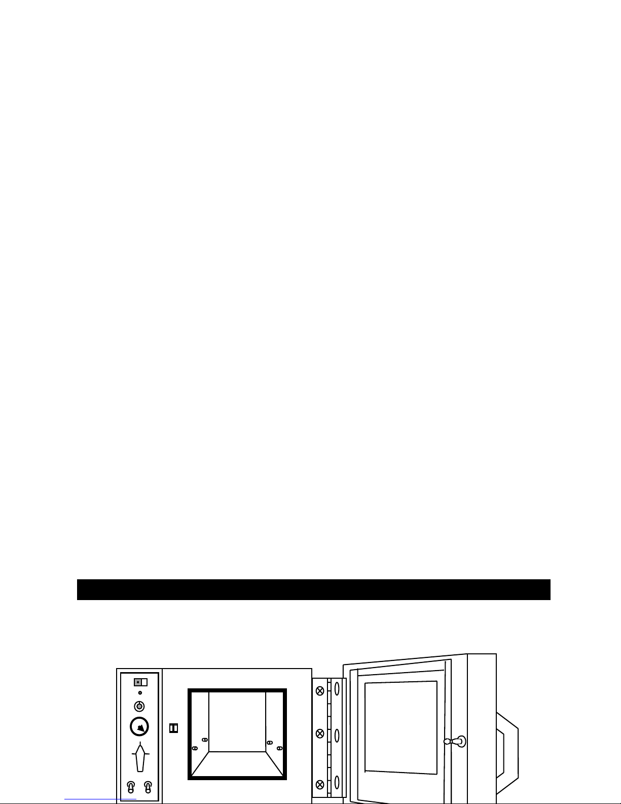
All controls and connections (except electrical power) are located on the
front vertical panel—these include lighted power switch, vacuum gauge,
temperature control, vacuum control valve and nickel-plated hose connectors.
Uniform radiant wall heat, with no internally exposed heaters, optimizes
chamber space. 3-inches (76 mm) of glass wool insulation throughout helps
maintain temperature uniformity effectiveness. Temperature is controlled either
by a hydraulic thermostat (most models) or microprocessor-based temperature
controller (model 3608MP only) and can be read on a dial thermometer, LCD or
LED display.
The chamber of the unit is not designed for exposure to concentrated
solvents, oils, concentrated acids or dilute sodium hydroxide.
Vacuum levels are precisely held between 0 and 30-inches of mercury.
The silicone door gasket assures a tight seal at all vacuum levels. A
high strength tempered glass window allows full view of oven contents. Two
aluminum shelves provide good heat conduction to samples. The shelf
assembly removes for easy cleaning.
IMPORTANT NOTE: WHEN OPERATING IN A VACUUM, THERE IS NO TRANSFER OF HEAT
FROM THE EVACUATED CHAMBER INTERIOR TO OBJECTS WITHIN THE CHAMBER
UNLESS THEY ARE RESTING DIRECTLY UPON ONE OF THE SHELVES—DO NOT PUT
INSULATING MATERIAL BETWEEN A SHELF AND A VESSEL BEING HEATED. ALSO,
BE SURE THAT A THERMOMETER’S SENSOR ELEMENT IS IN DIRECT CONTACT
WITH THE SURFACE OF THE CENTER SHELF WHEN TAKING A READING.
MODEL DESIGNATIONS AND THEIR FEATURES:
3608, 3608-1CE, 3618 and 3618-1CE: Models with dial thermometer.
3608-5, 3608-6CE, 3618-5 and 3618-6CE: Models with LED temperature display.
3608MP: Model with microprocessor temperature controller.
SECTION 3
SPECIFICATIONS
POWER REQUIREMENTS:
3608, 3608MP, 3608-5: 120 VAC, 50/60 Hz, 5.0 Amps, 600 Watts
3608-1CE, 3608-6CE: 240 VAC, 50/60 Hz, 2.5 Amps, 600 Watts
3618, 3618-5: 120 VAC, 50/60 Hz, 13.3 Amps, 1600 Watts
3618-1CE, 3618-6CE: 240 VAC, 50/60 HZ, 6.7 Amps, 1600 Watts
TEMPERATURE RANGE: All Models:

6
From slightly above ambient to 220ºC
THERMOMETER TYPE:
3608, 3608-1, 3618, 3618-1: Bimetallic, dial type; range from
0ºC to 300ºC in 5ºC increments
3608-5, 3608-6, 3618-5, 3618-6: LED Display; range from 0ºC to 300ºC
in 1ºC increments
CHAMBER DIMENSIONS:
3608, 3608MP, 3608-1CE, 3608-5, 3608-6CE: 10"W x 12"D x 10"H (25 x 30 x 25 cm)
3618, 3618-1CE, 3618-5, 3618-6CE: 14"W x 20"D x 14"H (36 x 51 x 36 cm)
OVERALL DIMENSIONS:
3608, 3608MP, 3608-1CE, 3608-5, 3608-6CE: 19-7/8"W x 16"D x 16¼"H (50 x 40 x 41 cm)
3618, 3618-1CE, 3618-5, 3618-6CE: 25"W x 25"D x 22"H (64 x 64 x 56 cm)
VOLUME:
3608, 3608MP, 3608-1, 3608-5, 3608-6CE: 0.7 cubic feet (19.8 liters)
3618, 3618-1CE, 3618-5, 3618-6CE: 2.3 cubic feet (65.1 liters)
NET WEIGHT:
3608, 3608MP, 3608-1CE, 3608-5, 3608-6CE: 83 lbs. (38 kg)
3618, 3618-1CE, 3618-5, 3618-6CE: 150 lbs. (68 kg)
UNIT’S ENVIRONMENTAL OPERATING CONDITIONS:
POLLUTION DEGREE: 2
INSTALLATION CATEGORY: II
ALTITUDE: 2000 Meters MSL (Mean Sea Level)
HUMIDITY: 80% maximum, non-condensing
ELECTRICAL SUPPLY: 120VAC or 240VAC
VOLTAGE TOLERANCE: ±10% of normal rated line
TEMPERATURE: 15ºC to 40ºC
PRODUCT USAGE: This product is intended for use indoors only
SECTION 4
INSTALLATION
√SHIPPING CARTON:
This should be inspected upon delivery. When received, carefully
examine for any shipping damage before unpacking. If damage is discovered,
the delivering carrier should both specify and sign for the damage on your copy
of the delivery receipt.
Open the carton carefully making certain that all parts are accounted for
before packaging materials are discarded—after unpacking, if damage is found,
promptly report it to the carrier and request a damage inspection promptly.

7
IMPORTANT: Failure to request an inspection of damage within a few
days after receipt of shipment absolves the carrier from any liability for damage:
you must call for a damage inspection promptly.
LOCATION:
Place the unit where it will be operated, away from drafts and wide
variations in ambient temperature. It should be near a power source that
matches the unit nameplate requirements. Allow clearance around the unit for
free air convection, hose/accessory attachment and user-access. DO NOT put
the oven on top of or underneath another oven, or on a combustible surface.
HOSE CONNECTIONS:
Connect a ¼-inch ID vacuum hose to the left hose connector on the
control panel that is marked "EVACUATE". Connect the other end of the hose
to a vacuum pump.
If operation will include replacing the vacuum in the chamber with an inert
gas such as carbon dioxide or nitrogen, connect a ¼-inch ID flexible hose to the
right hose connector that is marked "VENT" and to the regulator for the gas
supply. DO NOT use combustible, flammable or corrosive gases.
ELECTRICAL CONNECTION:
The unit is supplied with a 3-wire line cord. It should be plugged into an
outlet supplying the correct voltage for the unit and designed for 3-prong plugs.
For an outlet designed to accept 2-prong (ungrounded) plugs, the best
recommendation is to have a qualified electrician replace it with a new grounded
outlet.
If a plug must be installed, use only the 3-prong grounded type, rated for
the unit load requirements and matching the power outlet. Make sure the green
ground wire is secured to the plug ground post—refer to the upcoming wiring
schematics if necessary.
Turn the power switch OFF and insert the plug into the outlet.
FOR SERIES 3618 UNITS ONLY: Turn the power switch to the OFF position.
For the 120V unit, plug the power cord into a grounded 20-amp outlet; for the
240V unit, attach proper power plug to match the power outlet.
INSTALLATION:(Con’t)
THERMOMETER:
For models using the dial thermometer—3608, 3608-1CE, 3618 and
3618-1CE—place the thermometer so that the sensing element is in direct
contact with the top shelf. The dial should be easily visible through the glass
door.
Models with the LED display of temperature—3608-5, 3608-6CE, 3618-5
and 3618-6CE—are easily identifiable with the LED positioned just below
the power switch.
Model 3608MP features a microprocessor based temperature controller
with an incorporated display.

8
SECTION 5
FEATURES
CONTROL PANEL: POWER
1
TEMPERATURE
2
CHAMBER VACUUM
3
CLOSED

9
4
EVAC VENT
EVACUATE VENT
5
MODELS WITH DIAL THERMOMETER:
1. POWER SWITCH: Power is on to the unit when this switch lamp is lit.
(To reset the circuit breaker, press this switch to off, then on.)
#440-359-00 (120V), #440-292-00 (240V)*
2. CONTROL THERMOSTAT & STATUS LAMP: Adjust manually to control
oven temperature. A permanently-set bimetallic thermostat (not on the
panel) limits oven temperature at 250ºC should the control thermostat
fail.)
#920-283-00 (BIMETALLIC THERMOSTAT), #560-223-00 (KNOB) ; #360-235-00 (LAMP LENS)*
3. VACUUM GAUGE: Displays chamber level to 30-inches of mercury.
#660-103-00 (3608,-1, 3618, -1) *
4. VACUUM/VENT VALVE: 3-way valve draws, holds or releases a vacuum.
#950-125-00*
5. HOSE CONNECTORS: Marked "EVACUATE" and "VENT" for ¼" flexible
tubing to connect to a gas source or vacuum pump.
*AS LISTED ON UPCOMING REPLACEMENT PARTS LIST
FEATURES:(Con’t)
CONTROL PANEL:
POWER
1
TEMPERATURE ºC
2
TEMPERATURE
3
CHAMBER VACUUM
4
CLOSED
5
EVAC VENT

10
EVACUATE VENT
6
MODELS WITH LED READOUT:
1. POWER SWITCH: Power is on to the unit when this switch lamp is lit.
(To reset the circuit breaker, press this switch to off, then on.)
#440-359-00 (120V), #440-292-00 (240V)*
2. LED TEMPERATURE DISPLAY: Readout of temperature.
3. CONTROL THERMOSTAT & STATUS LAMP. Adjust manually to control
oven temperature. A permanently-set bimetallic thermostat (not on the
panel) limits oven temperature at 250ºC should the control thermostat
fail.)
#920-283-00 (BIMETALLIC THERMOSTAT), #560-223-00 (KNOB) ; #360-235-00 (LAMP LENS)*
4. VACUUM GAUGE: Displays chamber level to 30-inches of mercury.
#660-097-00 (3608-5,-6) OR $660-097-00 (3618-5, -6)*
5. VACUUM/VENT VALVE: 3-way valve draws, holds or releases a vacuum.
#950-125-00*
6. HOSE CONNECTORS: Marked "EVACUATE" and "VENT" for ¼" flexible
tubing to connect to a gas source or vacuum pump.
*AS LISTED ON UPCOMING REPLACEMENT PARTS LIST
FEATURES:(Con’t)
CONTROL PANEL:
POWER
1
TEMPERATURE
2
CHAMBER VACUUM
3
CLOSED
4
EVAC VENT

11
EVACUATE VENT
5
MODEL WITH MICROPROCESSOR CONTROLLER:
1. POWER SWITCH: Power is on to the unit when this switch lamp is lit.
(To reset the circuit breaker, press this switch to off, then on.)
#440-359-00 (120V), #440-292-00 (240V)*
2. TEMPERATURE CONTROLLER: PID based microprocessor controller
maintains chamber temperature.
#485-360-15
3. VACUUM GAUGE: Displays chamber level to 30-inches of mercury.
#660-103-00
4. VACUUM/VENT VALVE: 3-way valve draws, holds or releases a vacuum.
#950-125-00*
5. HOSE CONNECTORS: Marked "EVACUATE" and "VENT" for ¼" flexible
tubing to connect to a gas source or vacuum pump.
*AS LISTED ON UPCOMING REPLACEMENT PARTS LIST
SECTION 6
OPERATION
DANGER: DO NOT USE IN THE PRESENCE OF FLAMMABLE OR
COMBUSTIBLE MATERIALS OR EXPLOSIVE GASES. DO NOT USE IN THE
PRESENCE OF PRESSURIZED OR SEALED CONTAINERS—FIRE OR
EXPLOSION MAY RESULT, CAUSING DEATH OR SEVERE INJURY.
WARNING: DO NOT HEAT ANY SUBSTANCE ABOVE A TEMPERATURE
WHICH WILL CAUSE IT TO EMIT TOXIC FUMES—DEATH OR SEVERE
INJURY MAY RESULT.
TEMPERATURE CONTROL:
If it is necessary to set temperature before loading oven, push the power
switch ON and note that the power switch light is lit. Rotate the thermostat knob
to approximate the desired setting. The heater status lamp will be steadily lit until
the chamber temperature approaches the thermostat setting. Wait several heat
cycles until the temperature has stabilized.
Check the thermometer—dial or LED display—and rotate the thermostat
knob clockwise to raise the set point or counterclockwise to lower it. After oven
temperature has stabilized, check the temperature again and make further
thermostat adjustments until the thermometer consistently shows the

12
desired operating temperature. Push the power-switch OFF and allow the oven
to cool down, or, if a batch is ready, the oven can be loaded immediately.
LOADING THE OVEN:
For units which utilize a dial thermometer, the thermometer can be
removed and put back after loading if that is more convenient. Note that the
thermometer sensing element must be in direct contact with a shelf for an
accurate reading.
For best results, distribute the load evenly in the chamber, at least 1-inch
away from chamber walls and resting directly on the shelves. DO NOT PLACE
FLAMMABLE SOLVENTS OR VAPORS in the oven and avoid spilling acids. Be
careful not to heat substances above their auto-ignition temperatures.
While the oven door is open, apply high quality vacuum grease to the
door gasket. Close the door and push the power switch ON. If oven temperature
was not previously set, review above at “TEMPERATURE CONTROL” to set the
desired operating temperature.
MAINTAINING PROPER VACUUM LEVEL:
The vacuum level will decrease slightly over a period of time. To bring it
back up, rotate the vacuum/vent valve to "EVACUATE" and start the vacuum
pump.
When the vacuum gauge again shows the desired level, rotate the
vacuum/vent valve to the setting marked "CLOSED" and shut off the vacuum
pump.
OPERATION:(Con’t)
RELEASING THE VACUUM:
If the vacuum is to be replaced by ambient air, disconnect any tubing
attached to the hose connector marked "VENT" and rotate the vacuum/vent
valve to its "VENT” setting.
PURGING THE CHAMBER WITH INERT GAS:
Use only a non-combustible, nonflammable, non-corrosive gas—such as
nitrogen or carbon dioxide—if application requires replacing the vacuum with an
inert gas.
Connect ¼-inch ID tubing to the hose connector marked "VENT” and
connect the other end of the tubing to the regulator at the inert gas source.
Start the gas flowing at no more than 5 psi. Rotate the vacuum/vent
valve to the "VENT" position and shut off the regulator when the vacuum gauge
reads zero (normal atmospheric pressure).
WARNING: DO NOT PRESSURIZE THE CHAMBER ABOVE ATMOSPHERIC
PRESSURE—THE OVEN WILL NOT WITHSTAND A POSITIVE INTERNAL
PRESSURE. WHEN THE VACUUM GAUGE READS ZERO, SHUT THE GAS
OFF.
The oven does not require very much gas to fill the chamber:
3608, 3608MP, 3608-1, 3608-5, 3608-6: Interior volume is 0.75 cubic feet
3618, 3618-1, 3618-5, 3618-6: Interior volume is 2.30 cubic feet

13
UNLOADING THE OVEN:
When the bake is completed and the vacuum has been released or
replaced as described above and on the previous page, push the power switch
to OFF. Open the oven door and remove the dial thermometer. Take the
contents from the chamber and re-insert the thermometer with the sensing
element in direct contact with the center shelf.
OPERATION:(Con’t)
MICROPROCESSOR-BASED TEMPERATURE CONTROLLER, MODEL 3608MP
ONLY:
HEAT INDICATOR CHAMBER OR SET POINT TEMPERATURE
220.0
4WV
1. CONTROLLER SELF-TEST: When the oven is powered up the
controller will display 8888 along with
the three decimal points and the heat ON
indicator lamp. The display will then blank
out for 2 seconds before showing the
chamber temperature.
2. HEAT ON INDICATOR: The heat ON indicator lamp is lit when the
chamber heater is receiving power. The
lamp will normally flash when the chamber
temperature is at set point.

14
3. SET POINT ADJUSTMENTS: The temperature controller normally displays
the chamber temperature. To view or change
the temperature set point proceed as follows:
PRESS CONTROLLER
4View set point
4WDecrease set point
4VIncrease set point
A. Press and hold the star key and use either the up or down arrow
key to adjust the set point to the desired temperature. Release the
star key.
B. Allow at least 30 minutes for the chamber temperature to stabilize.
OPERATION:(Con’t)
TEMPERATURE CONTROLLER: (Con’t)
AUTO TUNE:
The auto tune program automatically adjusts the controller parameters to
achieve optimal temperature control.
It is not necessary to run the auto tune program when setting up the oven.
However, if the temperature appears to be unstable, the auto tune program can
be run using the procedure shown below:
FOR BEST RESULTS:
•Set the usual set point temperature and use normal load conditions.
•Allow the oven to stabilize at set point for at least 30 minutes.
AUTO TUNING PROCEDURE:
A. Enter the program mode by pressing and holding BOTH the up and down
arrow keys for 3 seconds.
B. Release BOTH arrow keys when tunE is displayed.
C. The controller display should now be alternating between tunE and
oFF.
D. Press and hold the “STAR” (4) key. Press and release the up arrow key
until At.SP is displayed. Release the “STAR” (4) key.

15
E. After one minute has elapsed, the controller display will begin to alternate
between showing the chamber temperature, tunE and At.SP.
F. Allow the program to run until the display again shows only the chamber
temperature.
OPERATION:(Con’t)
TEMPERATURE CONTROLLER: (Con’t)
TEMPERATURE CALIBRATION:
A. Place a calibrated thermometer near the approximate geometric center of
the chamber in a position that would allow it to be read through the glass
door.
B. Press and hold the “STAR” (4) key and using the up or down arrow key,
adjust the set point to the desired temperature.
C. Allow the unit to run for at least 30 minutes.
D. The controller display should now be indicating the set point temperature.
Make note of the thermometer reading without opening the glass door.
E. Press and hold both arrow keys until the controller display indicates
tunE. Release the arrow keys. Press and release the down arrow key,
the display should now indicate LEUL. Press and hold the “STAR” (4)
key and using the up arrow key adjust the display to read 3. Release the
“STAR” (4) key. Press and release the up arrow key until the display
indicates Zero. The display should now alternate between Zero and a
numerical value.
F. Using the examples shown below and the thermocouple value obtained in
step above, enter the correct Zero value into the controller by pressing the
“STAR” (4) key and using the up or down arrow keys. If there is already
a Zero value present then add the new value to the one already present.
Thermometer = 200 °C Thermometer = 200 °C
Controller Reading = 205 °C Controller Reading = 205 °C
Subtract = -5 °C Subtract = +5 °C
Enter Zero value of -5 °C Enter Zero value of +5 °C

16
G. When the correct Zero value has been entered, press and hold the two
arrow keys together until the display again indicates the chamber
temperature. If the procedure was done correctly, the controller display
should now agree with the thermometer reading to within ±0.5ºC.
H. Allow the unit to run for at least 30 minutes.
I. Re-check the thermometer reading, the controller display and the
thermometer should agree to within ±0.5ºC. If not repeat steps D, E and F
above.
SECTION 7
MAINTENANCE
BE ADVISED:
NOTE: MAKE NO ATTEMPT TO SERVICE OR REPAIR A LAB-LINE PRODUCT UNDER
WARRANTY BEFORE CONSULTING YOUR LAB-LINE DEALER. AFTER THE WARRANTY
PERIOD, SUCH CONSULTATION IS STILL ADVISED, ESPECIALLY WHEN THE REPAIR
MAY BE TECHNICALLY SOPHISTICATED OR DIFFICULT.
IF ASSISTANCE IS NEEDED BEYOND WHAT THE DISTRIBUTOR CAN PROVIDE, PLEASE
CALL THE LAB-LINE CUSTOMER RELATIONS DEPARTMENT AT (319) 556-2241 OR
(800) 522-5463. NO MERCHANDISE, HOWEVER, SHOULD BE RETURNED DIRECTLY TO
LAB-LINE WITHOUT PRIOR APPROVAL FROM LAB-LINE.
CAUTION: DISCONNECT PLUG FROM ELECTRICAL OUTLET BEFORE
ATTEMPTING ANY MAINTENANCE OR REPAIR OF THIS UNIT.
ROUTINE CLEANING:
Wash the cabinet with a solution of water and mild soap or detergent to
clean off surface dirt, marks or smudges.
Keep the vents clear of dust for free air circulation. This will add to the
service life of components.
The aluminum shelf assembly should be washed with a mild soap and
water. Do not use abrasive or halogen-based cleaners—they will damage the
finish. Rinse thoroughly and dry completely.
Wipe interior glass with an ammonia-based glass cleaner and a soft,
lint-free cloth.
Clean up spills inside the chamber as soon as possible to prevent them
from being baked on. When the oven is cool, use hot soapy water and a soft
cloth to clean the #304 stainless steel chamber. Do not use scouring pads with
metallic content, chlorine bleach or halogen-based cleaners. (Special order units
may come with stainless steel shelves, in addition to the stainless steel interior.)

17
CARE AND CLEANING OF STAINLESS STEEL:
CAUTION: DISCONNECT UNIT FROM POWER SOURCE PRIOR TO
CLEANING. WE RECOMMEND ALL SERVICE BE PERFORMED BY
QUALIFIED SERVICE PERSONNEL.
WARNING: ELECTROLYSIS CAN DAMAGE STAINLESS STEEL. THIS
OCCURS WHEN AN OBJECT IS ALLOWED TO REST DIRECTLY ON THE
SURFACE OF STAINLESS STEEL, TRAPPING MOISTURE THAT BECOMES
OXYGEN-STARVED, BUT IS SURROUNDED BY WATER-CONTAINING
OXYGEN.

18
MAINTENANCE:(Con’t)
THE ALLOY CALLED STAINLESS:
Stainless steel is an alloy of steel with chromium and nickel which
increase the metal’s resistance to rust and corrosion. Yet, if not properly cared
for, stainless steel can rust and corrode.
Exposure to air provides the passivation, or oxide layer coating, for clean
stainless by producing a thin, durable chromium-oxide film that forms rapidly
on the alloy surface to give stainless its characteristic “stainless” quality. Also
exposure of the surface to other oxidizing environments can produce a
passivating film or coating.
However, if free oxygen is not available due to scale or contamination
buildup the metal surface may become vulnerable to rusting and corrosion as
well as pitting. But by maintaining neutral pH and conducting frequent cleanings
with detergent and water, years of trouble-free service from stainless steel
products can be obtained.
SOME STAINLESS GUIDELINES TO CONSIDER:
Distilled water is recommended. Please note: if this water is very pure it
may be corrosive to stainless. When filling a bath or incubator, ALWAYS ADD 2
to 40 PPM (20 TO 40 MG/LITER) DISODIUM PHOSPHATE OR SODIUM
BICARBONATE, ADJUSTING DOSAGE TO PROVIDE A pH VALUE OF 7 TO 9.
If not available, use clean, aerated soft tap water provided the total solids
concentration is <500 PPM.
WE DO NOT RECOMMEND USING 18 MEG OHM DEIONIZED WATER.
If this is the only source of treated water available—mix with regular tap water
at a 50/50 ratio.
THE pH FACTOR:
Check pH regularly. If pH is <6.0, add disodium phosphate to increase pH
to a 7 to 9 value. Sodium carbonate or sodium bicarbonate may be used but
they tend to form scale which must be rinsed out regularly. If pH is >10.0, add
sodium bisulfate to decrease pH to a 7 to 9 value. Avoid adding harsh alkalines
or acids since these may cause localized corrosion and result in unstable pH.
SPECIAL CONSIDERATIONS:
WARNING: IF IT IS NECESSARY TO USE THE FOLLOWING CHEMICALS,
LIMIT EXPOSURE TIME TO A MAXIMUM OF 3 HOURS—ALWAYS CLEAN
SURFACES IMMEDIATELY AFTER USE.
Chemicals which should be limited to a 3 hour maximum exposure time to
stainless steel are:
Aluminum chloride E.D.T.A. Potassium permanganate
Barium chloride Ferrous chloride Potassium thiocyanate
Calcium chloride Lysol Sodium hypochlorite
Chlorinated Lime Mercury salts Stannous chloride
Citric acid (boiling) Phenol Tartaric acid
Dakin’s solution

19
MAINTENANCE:(Con’t)
BE ADVISED: NEVER USE THE FOLLOWING ON STAINLESS STEEL:
Aqua regia
Ferric chloride
Iodine
Sodium acid
Sodium azide
Chemical spills, especially those agents listed here, should be removed
as soon as possible and the stainless steel surface cleaned with mild soapy
water followed by a clean water rinse.
CLEANSING AGENTS:
Anti-fungal and anti-bacterial additives are permissible to use as long as
the pH of the aqueous solution is kept within the range of 7 to 9. These are
available through laboratory distributors—but be sure to CONFIRM that they are
not harmful to stainless steel.
CLEANING METHODS:
Do not use any metallic pads. Instead, for stubborn stains, use a plastic
light-duty cleansing pad and rub GENTLY in the direction of the metal grain.
If stains continue to persist, use one of the following chemicals and methods.
CAUTION: EXTREME CARE MUST BE TAKEN WHEN HANDLING THESE
MATERIALS. ALWAYS WORK IN AN AREA WITH ADEQUATE
VENTILATION. USE THE PRECAUTIONS AS OUTLINED IN THE MATERIAL
SAFETY DATA SHEET (MSDS) AND THE MANUFACTURER’S
INSTRUCTIONS FOR THE PRODUCT BEING UTILIZED. ALSO, FOLLOW THE
PERSONAL PROTECTION INDEX FOUND IN THE HAZARDOUS MATERIALS
INFORMATION SYSTEM (HMIS) SECTION OF THE MSDS.
NOTE: THE USE AND DISPOSAL OF THESE CHEMICALS MAY BE REGULATED BY YOUR
LOCAL CITY CODES; CONSULT THOSE REGULATIONS BEFORE OF DISPOSING OF
THESE MATERIALS.
•Any of a variety of “scale removers” available at local supermarkets or
hardware stores used for the cleaning of coffee marks, humidifiers or
vaporizers.
•A 15% to 35% phosphoric acid solution available from laboratory supply
distributors for scale and rust removal. Allow solution to soak the surface
affected until rust and scale is loosened. Immediately follow with a clean
water rise.
•Citric acid based cleaners.
•Bathroom tub and tile cleaners.

20
MAINTENANCE:(Con’t)
CLEANING METHODS: (Con’t)
•A mixture of 20% nitric acid and 1.5% hydrofluoric acid (or hyrochloric
acid). Swab solution on surface allowing it to remain until rust is loosened.
Immediately follow with a clean water rise. (This method should ONLY be
used if SEVERE rust and scale stains are present.)
•Oxalic acid 2% to 5% in warm water. Swab solution on surface allowing it
to remain until rust is loosened. Immediately follow with a clean water rise.
(This method should ONLY be used if SEVERE rust and scale stains are
present.)
Regardless of the approach utilized, ALWAYS follow the manufacturer’s
directions and allow the chemicals to do the cleaning with MINIMAL scrubbing.
Always follow cleanings with a clean water rinse. Air dry.
MATERIALS EFFECTIVE IN DISINFECTING:
•Glutaraldehyde
•Alcohol
BE ADVISED: THIS INFORMATION IS INTENDED AS GUIDELINES ONLY
AND LAB-LINE INSTRUMENTS, INC. MAKES NO CLAIM AS TO THE
SUITABILITY TO ANY PARTICULAR SITUATION. CONSULT YOUR STAFF
CHEMIST TO DETERMINE WHAT WOULD BE BEST FOR YOUR STAINLESS
STEEL PRODUCT AND LABORATORY.
DOOR GASKET LUBRICATION:
Apply a high-quality vacuum grease to the door gasket frequently,
especially before initiating a vacuum. Also apply vacuum grease to the gasket
after shutdown, if the oven will not be used in the near future.
This manual suits for next models
8
Table of contents
Other Lab-Line Laboratory Equipment manuals
Popular Laboratory Equipment manuals by other brands

PCE Health and Fitness
PCE Health and Fitness PCE-MSR 50 user manual

SH Scientific
SH Scientific SH-AC-60M manual

Apera Instruments
Apera Instruments LabSen761 user manual

Opentrons
Opentrons GEN1 quick start guide

Koehler
Koehler KV4000 Installation, operation and instruction manual

Sensorex
Sensorex 8000 Series Product Instruction Sheet