Labgear HDXS450P User manual

User Guide
HDXS450P
HDMI 50m 4 Way Splitter Extender Kit with POE
over CAT 5e/6/7
®

• To prevent re or shock hazard, do not expose any part of this device to rain or moisture.
• This product is for indoor use only
• Do not expose the product to extreme heat
• Do not disassemble any of the units in this kit they contain no user serviceable parts.
Refer servicing to qualied personnel only.
• This device should be operated using only the AC/DC adaptor supplied with it.
• Do not overload wall outlets and extension cords as this can result in the risk of re or electrical shock.
The HDMI 4 Way Splitter Extender splits the signal from a single source four ways and extends high denition
video and audio signals and IR, over a distance of up to 50m over four single CAT 5e/6/7 cable. It features EDID
management, which allows and encourages source and display “handshake”for seamless integration. Using only
a single cost eective CAT 5e/6/7 cable for each display, a high denition source with HDMI output can be
connected to high denition displays with HDMI inputs over long distances. Deep colour video, DTS-HD or Dolby
TrueHD audio are supported and compatible with this system. In addition, the system supports uni-directional IR
pass-through which allows for remote control of the source from the location of any connected display.
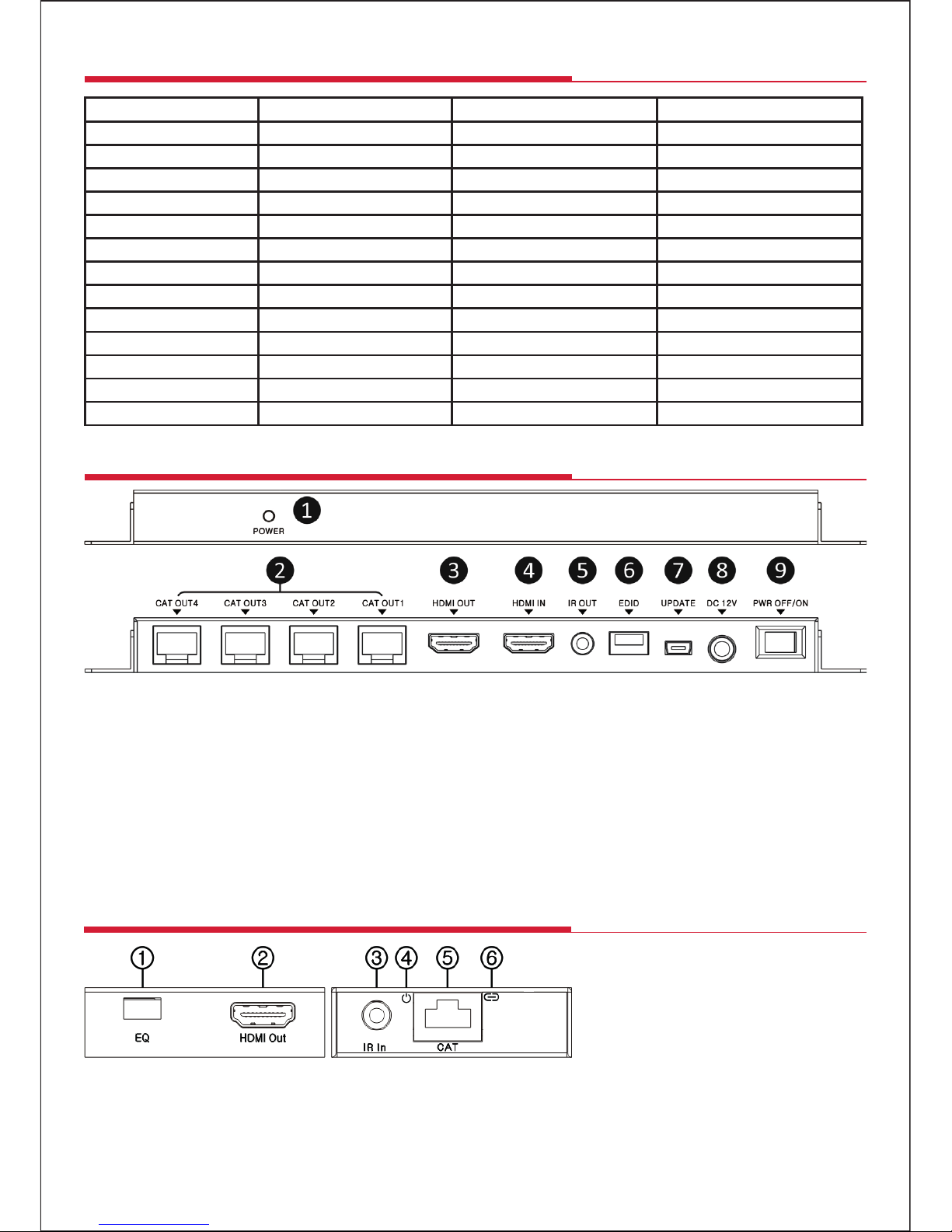
The extender comprises ve main units: a splitter/transmitter and four receivers. The splitter/transmitter captures
and splits the HDMI input and sends the signals over four Cat 5e/6/7 Ethernet cables to the four receivers (for best
results only use Ethernet cable with an all copper central conductor)..
The splitter/transmitter also reconstructs any IR control signals sent by the receivers and transmits them via the IR
sender to control the source.
The receivers equalize the transmitted HDMI signal, capture IR sigals via the IR receivers and send IR control
signals back to the source via the Transmitter.
• Splits the signal from a single source such as a satellite receiver, DVD or Blu-ray™ player four ways
• Extends HDMI/DVI/IR over four single CAT 5e/6/7 cables up to 50m for 1080p @ 50/60Hz signals
• HDMI loop-through socket allows the HDMI signal to be played on a local display
• Only one power supply needed, transmitter powers all four receivers over the Ethernet cables
• IR Sender and 4 IR Receivers supplied to enable IR source control
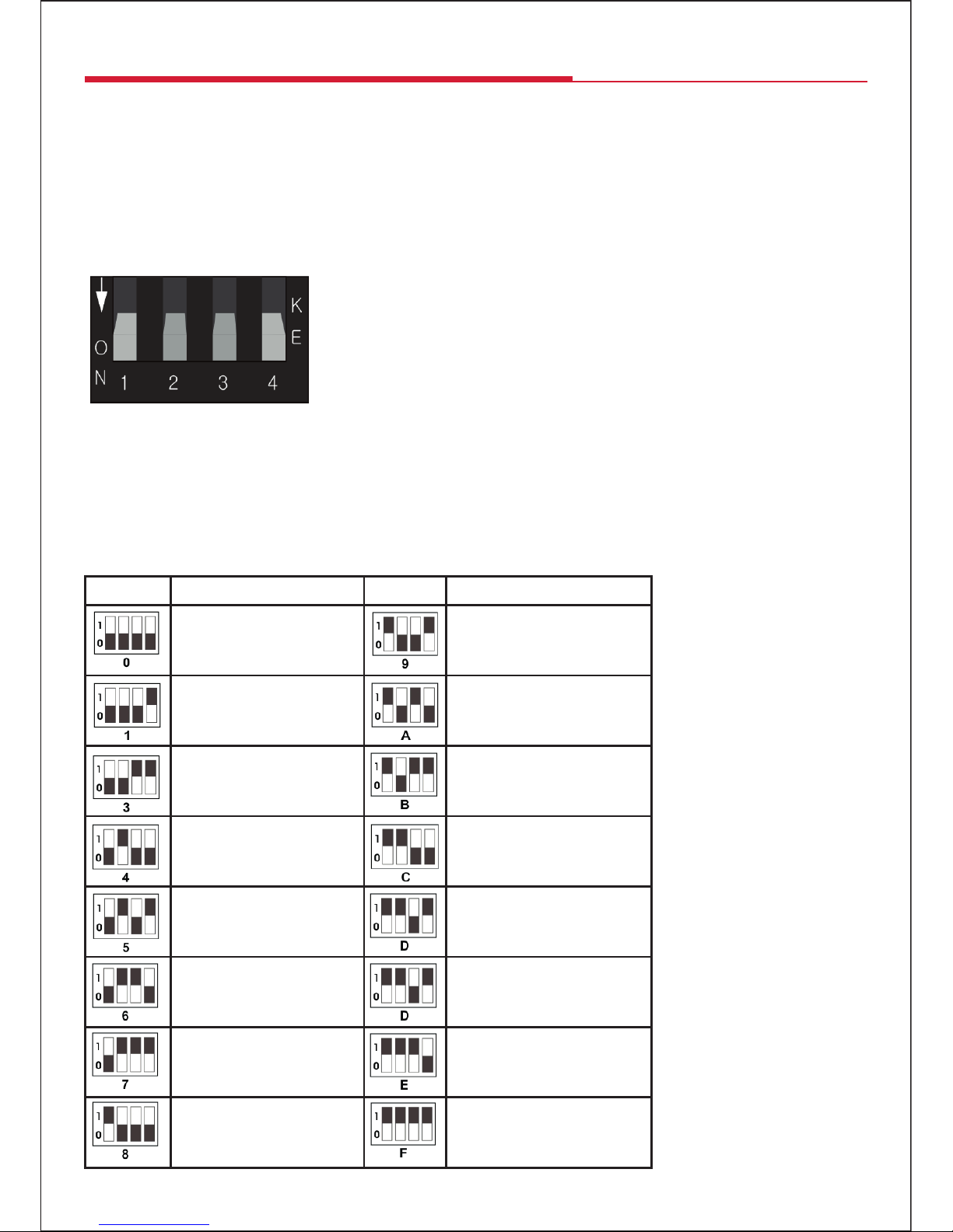
• Featuring EDID management switch
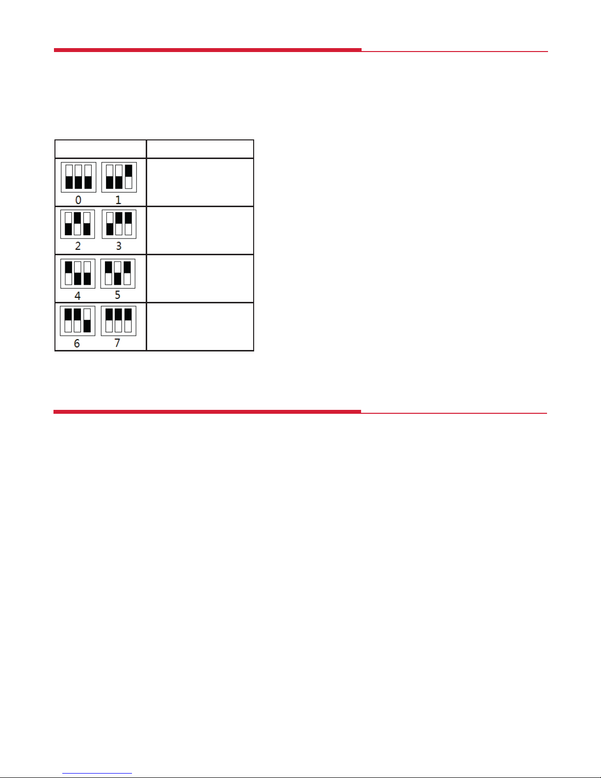
• Receiver equaliser switch allows signal strength and skew to be matched to cable length
• HDMI 1.3, HDCP 1.2 compliant
• Supports 1080p 3D systems and Blu-ray™ 1080p 24/50/60fps players
•
Supports VGA/SVGA/XGA/SXGA/UXGA/WUXGA
•
Supports 48bit deep colour (24bit 1080p @60Hz)
, RGB/YCbCr and xvYCC colour standard
• Supports DTS-HD/Dolby true-HD/LPCM 7.1/Dolby-AC3/DTS/DSD audio formats
General Safety
Features
Introduction
2
1x 4 Way HD splitter transmitter
4x HD receivers
1x 12V𝌂2.5A Power supply
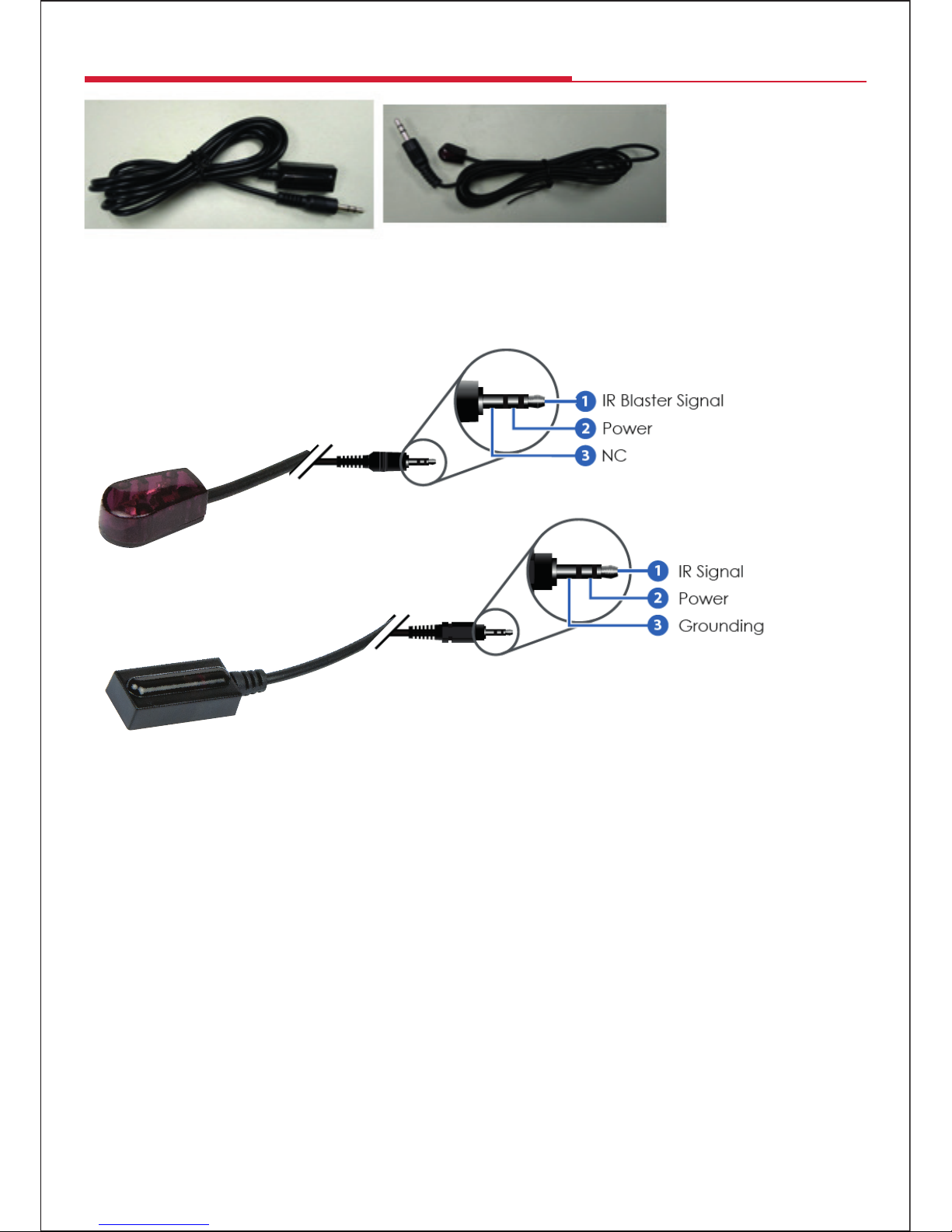
1x Wideband IR Blaster and Cable
1x Wideband IR Receiver and Cable
1x user manual
Extender Kit Contents

Specications
All Splitter/Transmitter Receivers
Max.Pixel Clock: 165 MHz
Max. Video Resolution: up to 1080p@60Hz
Power Consumption 8W max
Power Supply DC 12V𝌂2.5A
ESD Protection ± 8kV (air-gap discharge)
Human Body Model ± 4kV (contact discharge)
Operating Temperature 0°C ~ 40°C
Storage Temperature 20°C ~ 60°C
Relative Humidity 20~90% RH
Input Ports 1x HDMI, 1 x Mini USB 1x RJ45/1x IR IN
Output Ports 1x HDMI/4x RJ45/1x IR OUT 1x HDMI
Dimensions (mm): 210 (W) x 83 (D) x 17 (H) 79 (W) x 68 (D) x 17 (H)
Weight: 415g 4 x 131g
Splitter/Transmitter
TX 1. POWER LED: The red LED illuminates when the device is connected to a power supply.
TX 2. CAT OUT1- OUT4: Four RJ45 output ports to provide signal output to the IR receivers via CAT5E/6 cables.
TX 3. HDMI OUT: Local HDMI loop output port.
TX 4. HDMI IN: HDMI Input port. Connects to the AV source via an HDMI cable (not supplied).
TX 5. IR OUT: Connects the IR Blaster cable (supplied) allowing the blaster to be positioned in direct
line-of-sight of the source device sensor for IR signal transmission.
TX 6. EDID Selector: Selecting output signal format via EDID Selector. See the “EDID Switching”
TX 7. UPDATE: System software to update.
TX 8. DC IN: Pluging the 12V𝌂2.5A power supply into the unit.
TX 9. POWER SWITCH: Power ON\OFF Switch.
3
RX 1. EQ switch: HDMI Receiver equalizer switcher. See “Equaliser Switch”
RX 2. HDMI out: Connects an HDMI cable to the input port of your display such as an HDTV.
RX 3. IR in: Connects the IR Receiver to the IR sensor for IR signal reception from a remote control.
RX 4. Power LED: The LED will illuminate when the device is connected with power supply.
RX 5. CAT input: Connects a CAT5E/6 cable to one of the CAT output ports on the transmitter.
RX 6. Lock LED: The LED will illuminate when the HDMI signal from the transmitter is stable.
Receiver

4
Typical Splitter Extender System Setup
1. Connect a source such as an HD Blu-ray Player, game console, A/V Receiver, Cable or Satellite Receiver, etc. to
the HDMI input (TX 4) on the Splitter/Transmitter unit.
2. Connect a display such as an HDTV or HD Projector to the HDMI output (RX-2) on the Receiving unit.
3. Connect a single Cat5e/6 up to 50m/ to one of the four outputs (TX-2) of the Transmitting unit, and the other
end to the input (RX-5) of one of the Receivers.
4. Plug the cable end of the power supply included into the Splitter/Transmitter DC 12V socket (TX 8).
5. Then plug the 3 pin power supply into a mains electrical socket.

5
IR Receiver and Blaster Connections
IR Cable Pin Assignment
4x IR Receiver Cables
To control the source AV device (Blu-ray player or DVD player, etc) from the display location using a remote control:
1. Plug each IR Receiver’s 3.5mm plug into the HDMI Receiver IR in port (RX 3). Then position each IR Receiver sensor
close to the connected display where it will be in line of sight of the remote control. After testing you can use the
adhesive pad to hold the sensor in position.
2. Plug the IR Transmitter’s 3.5mm plug into the HDMI Splitter/Transmitter IR out port (TX 5). Then position the IR
Blaster as close as possible to and facing the sensor of the AV source use the adhesive pad to hold the sensor
in position.
1x IR Blaster Cable
IR Receiver Sensor
IR Blaster

6
EDID Control
Under normal circumstances, a source device (digital and analog) will require information about a connected
device/display to assess what resolutions and features are available. The source can then adjust its output to send
only resolutions and features that are compatible with the attached device/display. This information is called EDID
(Extended Display Information Data) and a source device can only accept and read one EDID from a connected
device/display. Likewise, the source can only output one resolution for use by a connected device/display.
The EDID switch allows for EDID learning or to pre-set an EDID to encourage a “handshake” between the display
and source.
Manual EDID Learning Mode
When you set the switch to any of the “0-8” sttings below, the Transmitter will
set a xed EDID for the source. See below the details for each EDID setting
description, please refer to the EDID table.
Auto EDID Learning Mode
When you switch to setting “9”, the Transmitter will copy the HDMI LOOP OUT port display EDID to source.
Attention: Please conrm the extender is working normally, if you want modify the new EDID to source, toggle the
EDID switch to the corresponding number rst, then plug the Transmitter power again. The extender will send the
new EDID to the source.
Auto EDID Switch Settings on the Extender Splitter
Position EDID Description Position EDID Description
1080p, 2CH AUDIO 3D,1080p, HD AUDIO
1080p, DOLBY/DTS 5.1 Copy EDID from the
Transmitter HDMI loop out
1080p, HD AUDIO 1080p, 2CH AUDIO
1080i, 2CH AUDIO 1080p, 2CH AUDIO
1080i, DOLBY/DTS 5.1 1080p, 2CH AUDIO
1080i, HD AUDIO 1080p, 2CH AUDIO
3D,1080p, 2CH AUDIO 1080p, 2CH AUDIO
3D, 1080p,DOLBY/DTS 5.1 1080p, 2CH AUDIO

7
Position Cable Length
under 15m (49.5ft)
15-30m (49.5 ft - 99ft)
30-40m (99ft - 132ft)
40-50m (132ft – 164ft)
Receiver Equaliser distance adjustment
If you see ickering or blinking image on the display, adjust the EQ switch to improve the cable skew. MAX stands
for the strongest HDMI signal level for the longest possible transmission length while MIN stands for the weakest
HDMI signal level for short transmission length. Adjust the signal level from MIN to MAX to nd the switch
position that gives you the best picture.
EQ Switch/Distance Settings on the Receivers
Troubleshooting
All displays connected to the Transmtter and Receiver should display the signal from the source device
connected to the Transmitter.
If no signal is being displayed, check the Receiver EQ switch setting is suitable for the cable length.
Make sure that you are using Ethernet cable with an all copper central conductor, for best results use
CAT 6 or CAT 7 cable.
If a display is not receiving a good signal, try changing the EDID setting manually to change the copy the EDID
information to the source (see the EDID section opposite) or access the display’s menu and adjust the resolution
(lowest to highest until a good picture displayed).
N.B. A 24Hz vertical refresh rate may work better than 60 Hz or higher.
Use the source remote pointed at the IR Receiver sensor to test IR functionality.
If the IR remote function is not responding, check that the IR Blaster and Receiver are placed correctly and are
plugged into the correct IR sockets on the Extender Receiver and Transmitter.

For further information, please contact:
Customer Careline:
08457 573 479
Local rate: UK Only
www.labgear.co.uk
© Philex Electronic Ltd 2018. V1.1 MK42 0NX
Waste electrical and electronic products must
not be disposed of with household waste.
Please recycle where facilities exist.
Check with your Local Authority for recycling advice.
Technical Support
Table of contents
Other Labgear Cables And Connectors manuals
Popular Cables And Connectors manuals by other brands

National Instruments
National Instruments LFH200 installation instructions

AV Access
AV Access 4KSP14-P user manual

Lightmaxx
Lightmaxx Platinum Series user manual

Marechal Electric
Marechal Electric MELTRIC CS1000 operating instructions

Lindy
Lindy 20275 user manual

ZHONGTIAN
ZHONGTIAN GPF-01 Operation manual