Labgear THOR 28013T User manual

USER GUIDE - 28013T
32-70"
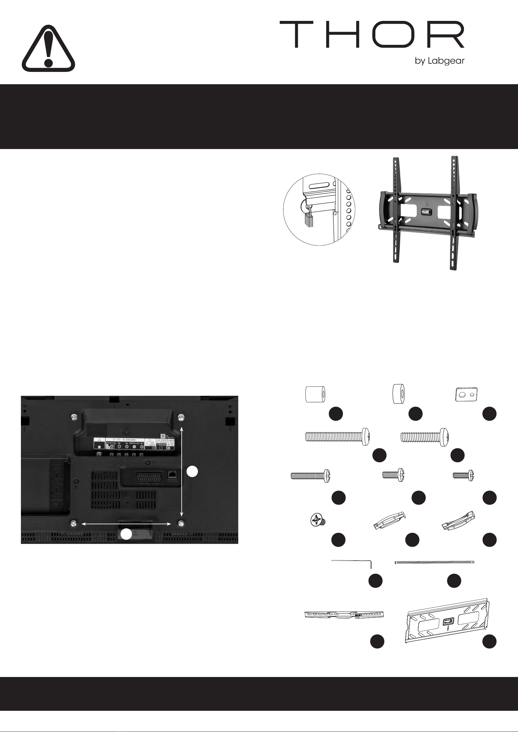
Anti-theft Heavy Duty Fixed TV Wall Mount
• TV Size range: 32-70"
• Maximum weight capacity: 45kg
• Mount function: Fixed
• Wall to TV distance: 26mm
• Compatible with VESA sizes:
200 x 200, 300 x 300, 400 x 200, 400 x 400
Components
Before installation check that you have all the components shown here and
that none of them are damaged.
WARNING
2
1
Wall Mount & VESA Compatibility
• VESA is the standard adopted by most TV manufacturers
for wall bracket mounting.
• There are 4 holes on the back of every at screen TV and the space
between the holes is governed by the VESA standard.
• VESA comes in a range of sizes depending on the weight and size of
the at screen TV; sizes 50 x 50mm, 75 x 75mm, 100 x 100mm, 200 x
100mm and so on... are standard. Not all at screen TVs are compliant,
contact the TV manufacturer for assistance if your TV does not appear to
comply with VESA.
• To check if your TV or monitor is compliant, look at the rear of the display
there should be 4 screw/bolt holes in a square pattern or in larger dis-
plays a rectangular shape.
• Measure the distances marked (2) (horizontal) x (1) (vertical)
below in mm to nd your VESA format.
• We have not supplied wall xings
with this product. All walls dier
in strength and thickness.
Consult a qualied installer or seek advice
from your local DIY/hardware store on
purchasing suitable wall xings to safely
mount the bracket on the type of wall
being used.
• Check the components list and images to
check there are no missing or defective
parts.
• Never exceed the Maximum
Weight Capacity.
• Read these instructions carefully
before installation. If in any doubt about
safely installing this product, contact a
professional installer for assistance.
• This product was designed to be installed
on wood stud walls and solid concrete/
brick walls. When xing to
walls screws/bolts should be xed into
bricks/stone not into mortar courses.
• Make sure the wall will support the
combined load of the equipment and
hardware. Also check for hidden
wiring or plumbing.
• Make sure that the heads of the screws/
bolts you buy as wall fastenings are the
correct size to hold the bracket securely in
position.
• Always ensure that all 4 bolts engage well
into the VESA threaded apertures on the
back of your TV; to at least a depth of 70%
of the total depth of the aperture to ensure
your TV is attached securely to the TV mount.
• For larger/heavier TVs we recommend
that you ask someone to assist you with
lifting and positioning your TV.
• This product is suitable for indoor use only.
• Improper installation or use of this
product can result in product failure,
damage or personal injury.
• This product contains small items that
could cause choking if swallowed, so keep
these items away from children and pets.
• Appropriate safety equipment and
proper tools must be used for installation.
Always check manufacturer’s operating and
safety instructions before using tools and
other equipment
.
(x4)
G
(x1)
F
(x1)
(x1)
A(x2)
B
(x1)
D
(x1)
C
(x4)
M(x8)
N(x8)
O
UK Distributor: Philex Electronic Ltd.,
London Road, Bedford, MK42 0NX, U.K.
EU Distributor: Philex Electronic Ireland Ltd.,
Robwyn House, Corrintra, Castleblayney,
Co. Monaghan, A75 YX76, Ireland.
© Philex Electronic Ltd. 2021. Vb1.2
E
M8 x 30 (x4)
KM8 x 50 (x4)
L
M5 x14 (x4)
HM6x14 (x4)
IM6x30 (x4)
J
M-A
M-GM-F
M-EM-D
M-CM-B
M-H

Select the correct size bolts to
t the VESA holes for your TV
H/I/J/K/L.
Attach the adaptor brackets
to the back of the TV by lining up
the VESA holesand using bolts
J/K/L, the washers Mand
the spacers Nand or O
(if the bolts are too long or the
TV has a curved surface) to x
the TV securely to the adaptor
brackets.
N.B. Always ensure that
all 4 bolts engage well
into the VESA threaded
apertures onthe back of
your TV.
Select the correct size bolts to t the
VESA holes for your TV H/I/J/K/L.
Attach the adaptor brackets to
the back of the TV by lining up
the VESA holes and using bolts
H/Ithe washers Mif spacers
are required see section 3b above.
N.B. Always ensure that all 4 bolts
engage well into the VESA threaded
apertures on the back of your TV.
Technical Support:
www.philex.com/support
1. Attaching End Caps
2a. Preparing Wall Fixings - Stud Walls
Tools required
2b. Preparing Wall Fixings - Concrete/Brick Walls
Tools required
3b. Attaching the Adaptor Brackets -
using spacers
4. Mounting the TV to the Wall Plate
5. Fitting the Locking Bar and Padlock
3a. Attaching the Adaptor Brackets
6. Securing the Adaptor Brackets
G
C
D
A
E
F
MM
JKJK
ON
O
The wall bracket Ais attached to the
wall using four appropriate screws/
bolts as shown in Fig.2. Make sure the
screws/bolts are suitable for wood and
large enough to support the weight
of the TV and bracket (if in doubt ask
for advice at your local DIY/hardware
store and remember to make sure
that the heads of the screws/bolts
are the correct size to hold the
bracket securely in position).
Mark and drill four holes into the wood
as close as possible to the centre of
theupright (you can use a stud detector
to nd stud positions).
To mark the holes, hold the bracket A
to the wall, using a spirit level to make
sure the bracket is level, and mark the
centre of each hole, see Fig.1. Drill the
four holes and attach the bracket A
to the wall using the appropriate
screws/bolts.
Fig.1
Fig.2
The process is the same as for
attaching to wood see Fig.4.
You will however need to use
suitable screws/bolts/wall
plugs for the type of wall you
are mounting onto and large
enough to support the weight of
the TV and bracket (if in doubt
ask for advice at your local DIY/
hardware store and remember
to make sure that the heads of
the screws/bolts are the correct
size to hold the bracket securely
in position).
When xing to walls screws/
bolts should be xed into bricks/
stone not into mortar courses.
Fig.3
Fig.4
Use the spirit
level to ensure
bracket is level
Tighten the top locking bolts Pin
the adaptor brackets, with the Allen
key supplied, to secure the adaptor
brackets to the wall plate.
P
M
M
N
O
L L
N
O
B
M
JK
N
M
O
L
H I
M
B
Slide the locking bar Cthrough the
guide in the base of the righthand End
Cap Ethen through the guide in the two
adaptor brackets and nally through the
guide guide in the lefthand End Cap F.
F
E
Attach a padlock (not supplied) to the
locking bar C to lock the bar in position,
to prevent removal of the TV from the
bracket.
(≥70% of depth)
FE
Use the spirit
level to ensure
bracket is level
(≥70% of depth)
Popular TV Mount manuals by other brands

Platinum
Platinum PT-UBAS21 Quick setup guide

Metra Electronics
Metra Electronics 107-GM3B installation instructions

Speaka Professional
Speaka Professional 1694483 Installation instruction

Alphason
Alphason ADUNIFIT-BKT installation instructions

New Star Computer Products
New Star Computer Products NS-SHELF100 instruction manual

Monacor
Monacor PAST-84/SW manual