Labotek Desiccant Flex Dryer User manual

MANUAL
Desiccant Flex Dryer
DFD
Serial No....................
ISO 08.01.02.39.GB
LT nr.: 986408
Rev. 01
Maskine indeks:

Rev. 01 Desiccant Flex Dryer DFD Side 1 af 40
1.0 CONTENTS........................................................................................................... 1
2.0 GENERAL INFORMATION........................................................................... 2
2.1 Application............................................................................................................................ 2
2.2 Restrictions ........................................................................................................................... 2
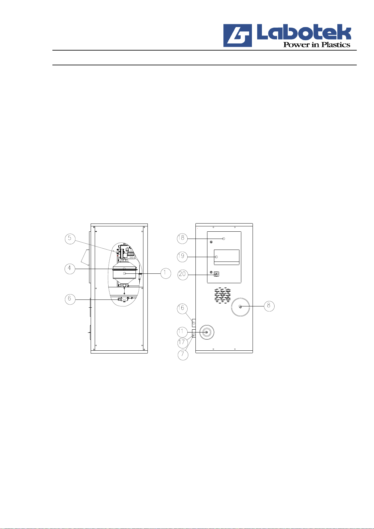
2.3 Design................................................................................................................................... 3
2.4 Relevant directives................................................................................................................ 4
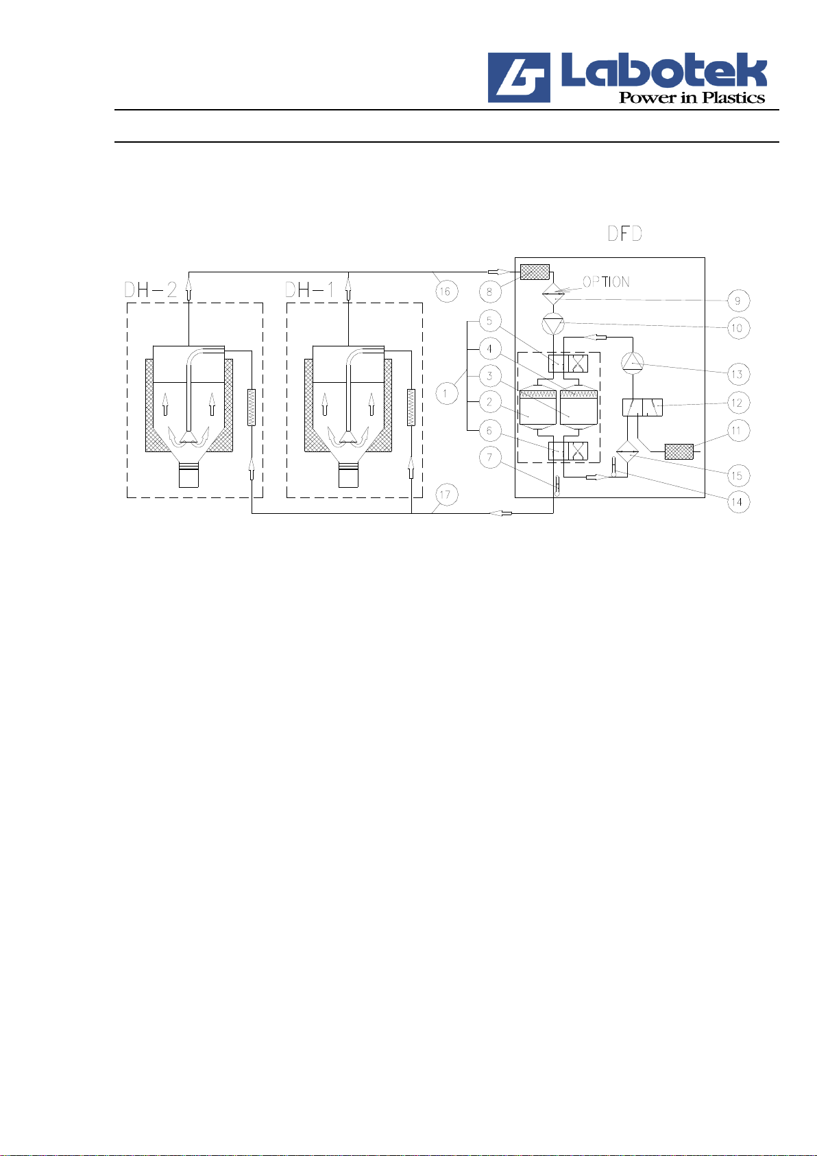
2.5 Operating principles.............................................................................................................. 4
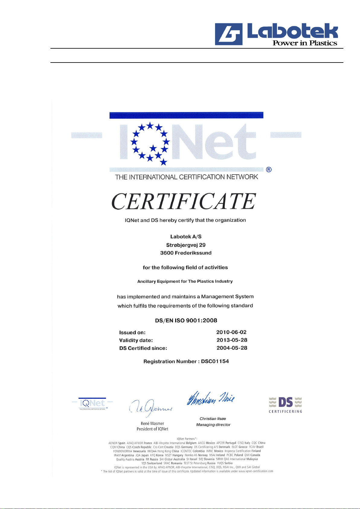
2.6 Certificates............................................................................................................................ 6
3.0 TECHNICAL DATA......................................................................................... 8
3.1 Technical specifications........................................................................................................ 8
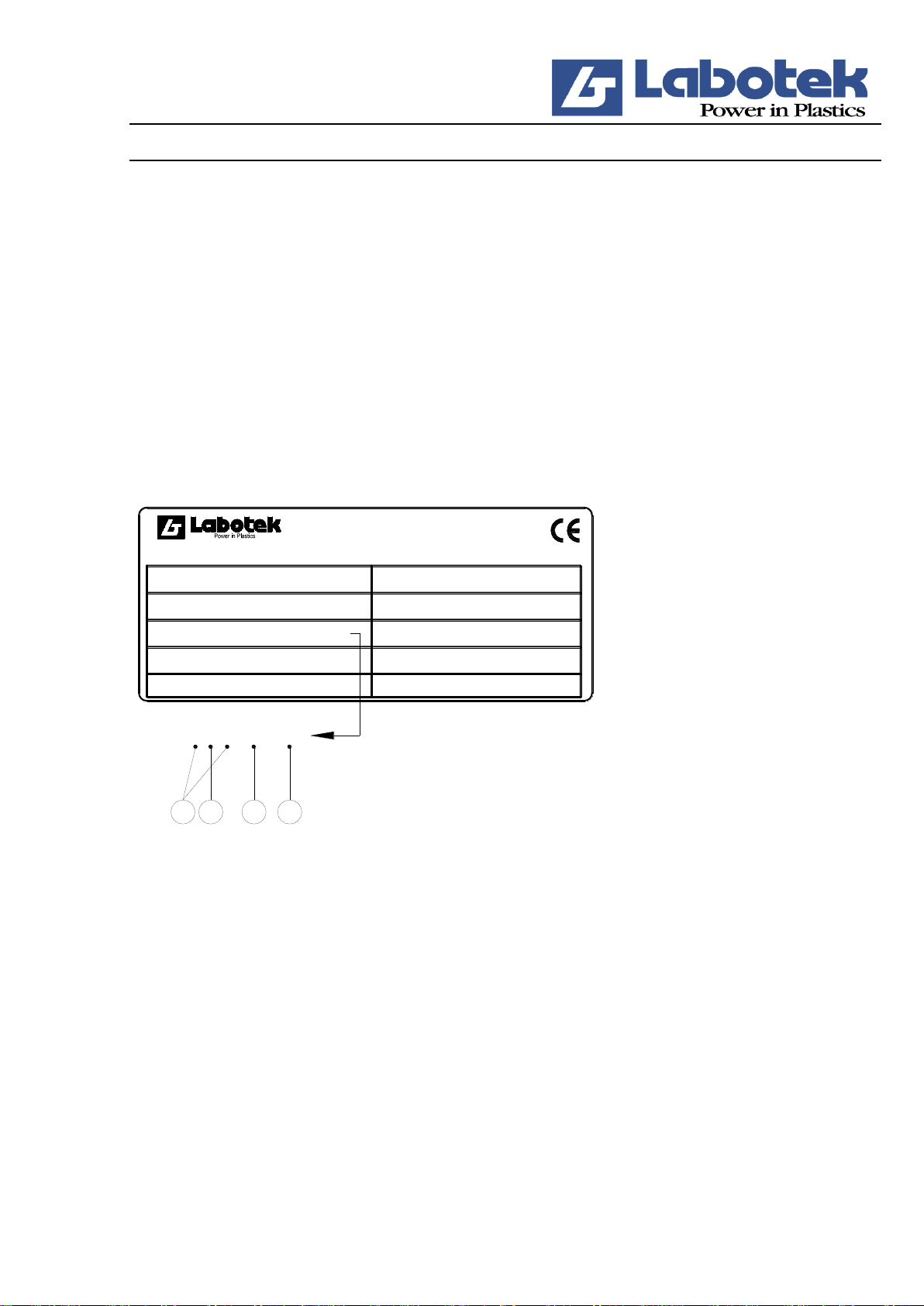
3.2 Typeplate .............................................................................................................................. 9
3.3 Dimensioned drawings ....................................................................................................... 10
3.4 Capacity table ..................................................................................................................... 11
3.5 Safety measures .................................................................................................................. 11
3.6 Noise level .......................................................................................................................... 12
4.0 INSTALLATION/OPERATION...................................................................12
4.1 Packing and transport.......................................................................................................... 12
4.2 Installation/connection........................................................................................................ 12
OPERATING THE SYSTEM..................................................................................14
5.1 Operating - LAB DRY........................................................................................................ 14
6.0 TROUBLESHOOTING .....................................................................................29
6.1 Machine gives en error message......................................................................................... 30
7.0 MAINTENANCE............................................................................................. 31
7.1 Maintaining the desiccant bed ............................................................................................ 31
7.2 Maintaining the air filters ................................................................................................... 31
7.3 Cleaning/checking the regeneration cooler......................................................................... 32
8.0 REPAIRS.......................................................................................................... 33
8.1 Replacing the desiccant bed assembly................................................................................ 33
8.2 Replacement of balls in the valve unit................................................................................ 36
8.3 Replacement of the motor for the change-over valve......................................................... 38
8.4 Replacement of blowers...................................................................................................... 39
8.5 Replaceing the fresh air valve............................................................................................. 40

Rev. 01 Desiccant Flex Dryer DFD Side 2 af 40
2.0 GENERAL INFORMATION
2.1 Application
The Desiccant Flex Dryer (DFD) is a central desiccant dryer designed for continuous drying of
granular plastic materials to a final moisture content of 0.02% or lower, depending on the material
involved. DFD is usually connected to a number of Drying Hoppers (DH hoppers).
See also separate manual on DH drying hoppers.
The DFD dryer has been designed for drying hygroscopic raw materials, nonhygroscopic raw
materials and regrinds in the temperature range from 60°C to 140°C with a temperature deviation of
±2°C or better.
2.2 Restrictions
The DFD unit may only be used for the purposes specified. It cannot be used for powders or liquids,
or for living creatures.
IMPORTANT!
The owner or the person responsible for connecting the apparatus and initiate operation shall make
sure that the installation is made in accordance with the requirements described in this manual.
Moreover, the owner or person must ensure that all safety procedures concerning the installation are
adequate and meet with local regulations.
The apparatus must be operated by a qualified operator only, following the procedures described in
this manual.
If the apparatus is operated by unauthorized or unqualified personnel resulting in damage to
property or personal injury, or is operated by or deposit with third party, all claim for compensation
covered by the product guarantee will become invalid and cancelled.
The right to carry out changes in the design is reserved to Labotek or his representative without
Labotek undertaking any obligation to change the design, neither for equipment already supplied.
The content of this manual is based on our present state of knowledge and is intended to provide
general information about the apparatus and its capabilities. The manual provides no further or
thorough description of the product characteristics or various fields of application.
The DFD unit may not be used in areas with danger of explosion.

Rev. 01 Desiccant Flex Dryer DFD Side 3 af 40
2.3 Design
2.3.1 DFD (Desiccant Flex Dryer)
Pos. Item
(1) Desiccant bed assembly
(4) Heating elements for regeneration
(5) Valve unit for desiccant beds (upper)
(6) Valve unit for desiccant beds (lower)
(8) Return air cartridge filter
(11) Fresh air filter
(16) Return air pipe
(17) Return air pipe
(18) Control cabinet
(19) Microprocessor control (control panel)
(20) Power switch
R2647
The Desiccant Flex Dryer (DFD) operates in a closed system and is fitted with two desiccant beds
to dehumidify the air before use. One of the desiccant beds will always be operative in the drying
cycle while the other bed will be regenerating or in stand-by mode ready for activation into the
drying cycle.
The DFD dryer operates on the adsorption drying principle, i.e. the water molecules pass a water
adsorbent agent (the desiccant) which adsorbs the water molecules and releases them again during
regeneration. The desiccant used in the DFD dryer is called a molecular sieve.
It has a large surface to which the water molecules can affix. The water is removed from the
desiccant by heating (regeneration).

Rev. 01 Desiccant Flex Dryer DFD Side 4 af 40
The adsorption and regeneration processes take place without chemical transformation of the
desiccant which therefore has a long life. Deterioration of the desiccant is caused solely by soiling
of the surface of the desiccant with oil, dust etc. The desiccant in the DFD dryer is therefore
protected by an efficient dust filter which can easily be cleaned and replaced.
Easy operation
Only international function keys with simple standard symbols are used in the control panel.
Desiccant bed assembly (l): Consists of two identical desiccant beds (2) and (3) with a built-in
heating element (4) for regeneration; the heating element is fastened between two valve units (5)
and (6).
Return air cartridge filter (8): Consists of one cartridge filter which is placed in a specially
designed box. The filter separates dust from the return air before it is recirculated through the
desiccant bed system.
Return air cooler (9) (optional): Reduces the drying air temperature before it is recirculated
through the desiccant bed to ensure optimal adsorption.
Desiccant air blower (10): Recirculates the drying air to the DH hoppers continuously.
Fresh air filter (11): Filters dust from the ambient air before it is used in the regeneration cycle.
Fresh air valve (12): A 3-way/2-way valve change-over between open and closed systems in the
regeneration phase.
Regeneration blower (13): Recirculates the regeneration air in the regeneration phase.
PT 100 sensor for regeneration air (14): Regulates the regeneration phases on the basis of
measurements of the regeneration temperature.
Regeneration air cooler (15): Is connected in the fi nal phase of the regeneration cycle to cool the
desiccant bed in a closed system.
Control cabinet (18): The control and electric and operating components are located inside the
cabinet or on the outside of the cabinet.
2.4 Relevant directives
We refer to accordance agreement attached.
2.5 Operating principles
2.5.1 Drying (Fig. R1862)
The drying air is circulated in a closed system by means of the desiccant air blower (10). The air is
dried in one of the two desiccant beds (2) or (3), and the dew-point temperature is lowered to below
-30°C.

Rev. 01 Desiccant Flex Dryer DFD Side 5 af 40
After the drying air has heated the raw material and transformed the moisture to water vapour, it is
fed back through the return air cartridge filter (8). The humid air may then be cooled by the return
air cooler (9) (optional) just before it reaches the blower (10).
R1862
2.5.2 Regeneration (Fig. R1862)
The DFD dryer has 2 desiccant beds (2) and (3) with molecular sieves for dehumidifying of the
drying air. One of the beds is always operative in the drying cycle whereas the other is either
regenerating in the regeneration cycle or, when fully regenerated, is in stand-by mode.
Regeneration occurs when hot air passes through the desiccant bed (2) or (3).
The regeneration blower (13) takes in ambient air through the fresh air filter (11) and the fresh air
valve (12) and sends it to the heating element for regeneration (4) where the air temperature is
increased to approx. 180°C. The moisture adsorbed in the desiccant bed is evaporated and is forced
into the ambient air in the form of water vapour.
In the last phase of the regeneration cycle, the heating element for regeneration (4) is disengaged
and as the position of the fresh air valve (12) changes, the air is recirculated in a closed system
where the air is cooled down through the regeneration air cooler (15).
The desiccant beds (2) and (3) are placed between 2 automatic, double-acting valve units (5) and (6)
ensuring that one of the desiccant beds is always operative in the drying cycle and the other in the
regeneration cycle. The desiccant beds switch every 90 to 180 minutes depending on the load on the
desiccant beds.
The time required for regeneration of a desiccant bed, depending on the amount of moisture
adsorbed, is controlled by the regeneration sensor (14) which is mounted on the discharge pipe of
the regeneration cycle.

Rev. 01 Desiccant Flex Dryer DFD Side 6 af 40
2.6 Certificates
2.6.1 IQ-Net Certificate

Rev. 01 Desiccant Flex Dryer DFD Side 7 af 40
2.6.2 ISO- Certificate

Rev. 01 Desiccant Flex Dryer DFD Side 8 af 40
3.0 TECHNICAL DATA
3.1 Technical specifications
Tekniske specifikationer
DFD 100
DFD 150
DFD 200
Supply voltage:
3 ~50/60 Hz , 380/415/440 V
Installed power excl. DH [kW]
5,5/5,8
5,5/5,8
7,3/7,7
Blower motor, drying:
3-phase 50/60 Hz [kW]
1,5/1,9
1,5/1,9
3,4/4
Air volume [m3/h] 50/60 Hz
100/120
150/180
200/240
Air Pressure [mm WS]
2400/2880
2400/2880
2400/2880
Blower motor, regeneration:
3-faset 50/60 Hz [kW]
0,37/0,44
Dew-point temp. [°C]
-30
Heating element regeneration [kW]
2x3,5/3,5
Power consumption [kWh]
2,0-2,6
3,5-4,5
5,5
Noise level [dBA]
65
65
65
Connecting cable [m]
3
We reserve the right to make changes to the specifi cations without notice.

Rev. 01 Desiccant Flex Dryer DFD Side 9 af 40
3.2 Typeplate
The identification number consists of a code (A) and (B), a type number (C) and a serial number
(D).
A) Identify the year in which the machine was manufactured. Example: 0SA8 = 2008
B) The first letter identifies the machine.
SA = Standard machine.
KA = Special customised design.
L = Low temperature (below 60°C)
H = High temperature (over 140°C)
The second letter states the machine index, in other words the current version.
Strøbjergvej 29
DK-3600 Frederikssund
Denmark
Tel: +45 48 21 84 11
Fax: +45 48 21 80 00
www.labotek.com
Type:
Model no:
Serial no:
Date: kW:
Hz:
Volt:
Prefuse:
Amp:
1KC1 10700501
CB D
50 Hz
7 kW
16 Amp
16 AMP
3x400+PE
2011.04
1KC1 10700501
101653
DFD200
A
Diagram:
R2648
C) The type number consists of two/three digits characterising the machine type:
DFD 100:
24
DFD 150:
16
DFD 200:
107
D) The serial number is a four/five-digit number referring to the individual manufacturing number
of the machine.

Rev. 01 Desiccant Flex Dryer DFD Side 10 af 40
3.3 Dimensioned drawings
R1877
A
B
C
E
DFD 100
660
1600
660
720
DFD 150
660
1600
660
720
DFD 200
660
1600
660
720
All measurements are in mm.

Rev. 01 Desiccant Flex Dryer DFD Side 11 af 40
3.4 Capacity table
Rawmaterial
Recom-
mended
dry time
[h]
Recom-
mended
drying
temp. °C
Drying capacity kg/h at bulk density
0.6
DFD100
DFD150
DFD200
ABS
Acrylnitril-Butadien-Styrol
2
80
70
105
140
PA
Polyamid 6/6.6/10
3
75
46,5
70
93
PA
Polyamid 11/12
4
75
35
52,5
70
PC
Polycarbonat
2,5
90-130
56,5
84
113
PE
Polyethylen
1
120
110
165
220
PE
Polyethylen, sort
2
90
55
82,5
110
PETG
Polyethylenterephtala-
glykol
4,5
65-70
38
56,5
76
PETP
Thermoplastik polyester
2
120
85
127,5
170
PI
Polyimid
2
120
70
105
140
PMMA
Methylmethylmethacrylat
3
80
46,5
70
93
POM
Polyacetal
3
100
46,5
70
93
PPO
Polyphenylenoxid
2
100
70
105
140
PSU
Polyphenylensulfid
3
120
46,5
70
93
PUR
Polyurethan
3
90
46,5
70
93
PVC
Polyvinylklorid
2
60-70
70
105
140
SAN
Styrol Acrylnitril
2
80
70
105
140
SB
Styrolbutadien (PS slagfast)
2
80
70
105
140
See capacity table for desiccant dryers concerning recommended drying times, or ask the supplier
of the appropriate raw material.
For drying temperatures above 140° or below 60°C only HT/LT versions can be used.
The above capacity table states recommended values only, based on the drying of the specific
materials down to a residual moisture content of 0.02% which, however, will vary depending on the
type of material.
The capacities are based on a general bulk density of 0.6 with the exception of PE and PETG to
which a bulk density of 0.55 and 0.85 respectively forms basis.
The original moisture content in the material and any additives can prolong the drying time and
hence reduce the specified capacities.
3.5 Safety measures
The alarms fitted on the DFD dryer activate a code. The alarm can be connected to a yellow
flashing light on the DFD dryer.

Rev. 01 Desiccant Flex Dryer DFD Side 12 af 40
If over-temperature (excess temperature) occurs in the DFD dryer, the signal to the DH hoppers, the
heating elments and the blowers in the DFD dryer is interrupted.
A communication cable between the drying hoppers and the DFD dryer ensures that none of the
drying hoppers can be operated if the desiccant air blower of the DFD dryer is not running.
DH hopper
If over-temperature (excess temperature) occurs in a DH hopper, the heating element of the drying
hopper is disconnected. Optionally, the disconnection may be supplied 3-phase.
A warning is displayed on the catch box (if installed) to prevent fingers from getting stuck in the
pneumatic sliding valve.
A warning of the discharge of hot air is displayed at the air outlet pipe.
A warning of the danger of burns is displayed on the heating element on the DH hoppers.
Warning:
The return air pipe (16) may be hotter than 60°C at very high drying temperatures
and very low material flow.
See also separate manual on DH drying hopper.
3.6 Noise level
Noise level dBA according to DS/ISO 3746:
DFD 100:
65
DFD 150:
65
DFD 200:
65
4.0 INSTALLATION/OPERATION
4.1 Packing and transport
The DFD dryer normally comes ready-fitted with the DH hoppers and only electricity and suction
probes etc. need to be connected.
If the DFD dryer is supplied with separate hoppers, the system will be packed as follows:
Package no. 1: DFD desiccant dryer
Package no. 2: DH drying hopper
4.2 Installation/connection
When installing the DFD dryer, the minimum space requirement must be taken into consideration.
4.2.1 External power supply
The following external standard power supply is required:
Power supply

Rev. 01 Desiccant Flex Dryer DFD Side 13 af 40
Installation of compressed air 1/4" BSPF (5-7 Bar)*
Connection for water supply 1/2" RG (max. 8 Bar)**
* Where a pneumatic slide valve (optional) is fi tted under the DH hoppers.
** HT/LT models are fitted with a cooler which needs connection to water. Water inlet (27) and
water outlet (28) (½” RG).
Maximum pressure: 6 bar
Water volume: 250 l/h
Cooling water temperature in/out: 15/40°C
R1070_R01

Rev. 01 Desiccant Flex Dryer DFD Side 14 af 40
5.0 OPERATING THE SYSTEM
1: Main switch (1) for connection of voltage and emergency stop. Main switch should not be used
for on / off function of the machine as this can cause overheating of heating elements.
For daily on / off function, use on / off switch on Lab-Dry control.
2: Lab-Dry control (.2) for readout of operating status, alarm messages and input of operating
parameters
5.1 Operating - LAB DRY
DFD is controlled via the MP-based control unit’s colour touch screen (.2). The touch screen shows
graphically the machine’s operating status. The touch screen is activated by touching the screen
lightly.
LAB-DRY has a standby function in order to prolong screen life. The screen automatically goes to
standby 10 minutes after the last touching of the screen. The screen moves out of standby
immediately upon touching the screen.

Rev. 01 Desiccant Flex Dryer DFD Side 15 af 40
DFD is equipped with automatic calculation of drying time, based on the recorded amount of
moisture in desiccant beds. The automation ensures minimal energy consumption.
Attention!
LAB-DRY contains control programs for several machine types. It is therefore important the correct
machine type be chosen and its icon shows in the lower right hand corner of the screen. For DFD
100-200 selects program M-DFD/P4. Selecting a program / machine type carried out at 3-pol. Dip -
switch on the rear of the circuit board.
Hereafter the display will be referred as M-DFD.

Rev. 01 Desiccant Flex Dryer DFD Side 16 af 40
Normal operations
4-5 seconds after the machine is turned on, the screen will show the operating menu.
5.1.1 Operating menu
Lock /Unlock-button. The button must be green before any of the other buttons can be
operated. A short push on the button will allow operation of the Start/Stop and Alarm
buttons.
A longer push (minimum 3 seconds) will allow operation of the SET button (indicated
by green icon).
Start/stop-button: Starts and stop the entire machine.
Attention!
When the machine is switched off, conveying and heating elements stop immediately.
Motors for drying and regeneration will continue to run for 5 min. for cooling the
heating elements and then stop
SET-menu: In order to change the operating parameters in the Setup menu, the
Open/Close button must be depressed a minimum of 3 seconds. Thereafter the Set
button will change colour from red to green.
Touching the SET button will bring forth the Setup menu.
Alarm info: In case of an operating alarm, this button will become visible. A short
touch on the button will display the alarm status.
Lock / Unlock
Setup menu
Alarm info
Start / Stop

Rev. 01 Desiccant Flex Dryer DFD Side 17 af 40
5.1.2 Setup menu
Options menu: A password is required before admittance to this menu can be gained.
Clock-button: Allows setting of the clock and delayed timer start.
The green dots on various areas of the menu are activation buttons that allow a change
in the parameter of the specific area/machine.
On DFD without options installed, there will be green space for parameter selection.
ESC: Brings you back to the operating screen.
Options menu,
(password required)
ESC
Clock/time
Temp. process air, cooler
Filter alarm
Temp. Process air, alarm
Temp. Return air, cooler

Rev. 01 Desiccant Flex Dryer DFD Side 18 af 40
5.1.3 Options menu
DFD can have various options. A common setup of these options is that after installation, they must
be activated via the options menu. The chosen options and their status will thereafter be shown on
the operating screen.
The options menu is password protected to avoid unauthorized changes.
In the password menu, enter the default Password (2404) and press Enter.
Thereafter the screen will show the options and general parameters.
Numerical values to allow entering of 4 digit password.
Back: Erases input value
Enter: Push enter after entering 4 digit password
ESC: Brings you back to the setup screen.
The Options menu is divided into two sections with the same icons as are found on the operating
screen. Options that can be chosen are marked with colours:
Green: option is turned on.
Red: option is turned off.
Back
ESC
Enter

Rev. 01 Desiccant Flex Dryer DFD Side 19 af 40
Section on the left:
Six buttons for options, for the Drying system.
Section on the right:
Four buttons for options, for the total machine.
Drying system:
OFF/ON choice of the process air temperature alarm with Pt 100 sensor. Parameter
for alarm temperature is entered in set-up menu via parameter setting.
OFF/ON choice of the process air cooler with regulating of the max. process air
temperature Remark: Process air Pt100 sensor shall be installed to use this option.
Parameter for the max. process air temperature is entered in set-up menu via
parameter setting.
OFF/ON choice of the return-air cooler with regulating of the max. return-air
temperature. Parameter for the return air temperature is entered in set-up menu via
parameter setting.
OFF/ON choice of the return-air filter alarm.
OFF/ON choice of the dewpoint measurement. The optional dewpoint
measurement device is activated here and the dewpoint will be shown continuously
on the operating screen.
Choice of temperature scale, either °Celsius or °Fahrenheit. Choice is shown on the
button. The default value is Celsius.
Drying system
Total machine
Filter alarm
Scale 0°C/0°F
Dew point sensor
Process air temp./alarm
Process air cooler
Return air køler
This manual suits for next models
1
Table of contents