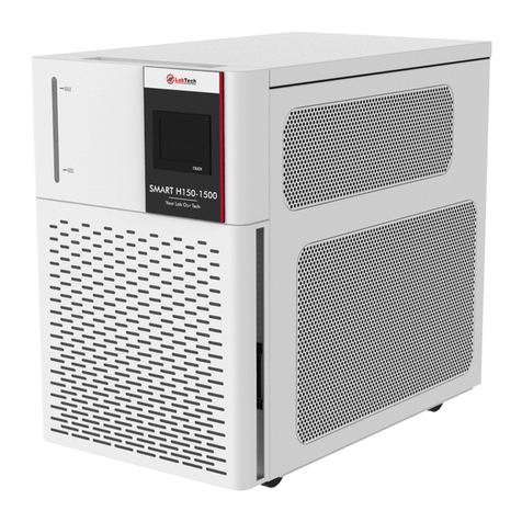
Labtech H50 SMART Series User manual

H50/150 Smart –User Manual
www.labtechsrl.com
Page 2 of 32
INDEX
DISCLAIMER ..............................................................................................................................................................4
INTRODUCTION ....................................................................................................................................................5-7
About your system................................................................................................................................................... 5
Compliance ............................................................................................................................................................. 5
WEEE/RoHS ............................................................................................................................................................ 5
Warranties and Liabilities ......................................................................................................................................... 6
Conventions ............................................................................................................................................................ 7
Contact us............................................................................................................................................................... 7
SAFETY RULES .......................................................................................................................................................8-9
General Information................................................................................................................................................. 8
Electrical safety ....................................................................................................................................................... 8
Fire safety............................................................................................................................................................... 8
Chemical safety ....................................................................................................................................................... 8
Recommendations ................................................................................................................................................... 8
Other Information.................................................................................................................................................... 9
GENERAL INFORMATION ............................................................................................................................... 10-15
MODEL: H50..................................................................................................................................................................10
Control Panel .................................................................................................................................................................... 10
Front View ........................................................................................................................................................................ 10
Rear View ......................................................................................................................................................................... 11
Specification ..................................................................................................................................................................... 11
MODEL: H150................................................................................................................................................................12
Control Panel .................................................................................................................................................................... 12
Front View ........................................................................................................................................................................ 12
Rear View ......................................................................................................................................................................... 13
Specification ..................................................................................................................................................................... 14
Magnetic PRG & PR Series Pump Capacity................................................................................................................ 15

H50/150 Smart –User Manual
www.labtechsrl.com
Page 3 of 32
INSTALLATION .............................................................................................................................16-19
Site Requirements ................................................................................................................................................... 16
Positioning the instrument........................................................................................................................................ 16
Electricals Requirements .......................................................................................................................................... 17
Plumbing Requirements ........................................................................................................................................... 18
Model: H50 ....................................................................................................................................................................... 18
Model: H150 ..................................................................................................................................................................... 18
Fluid Requirements .................................................................................................................................................. 19
Water Quality .......................................................................................................................................................... 19
OPERATION ..................................................................................................................................20-26
LCD Controller ................................................................................................................................................................20
Change Setpoint..................................................................................................................................................... 20
Touch Controller ........................................................................................................................................................... 21
Main Interface................................................................................................................................................................... 21
Main Menu........................................................................................................................................................................ 22
Parameter Setting.............................................................................................................................................................. 22
System Setting.................................................................................................................................................................. 24
Factory Reset.................................................................................................................................................................... 24
Alarms ................................................................................................................................................................... 25
Temperature Alarm............................................................................................................................................................ 25
Liquid Level Alarm ............................................................................................................................................................. 26
Liquid Pressure Alarm ........................................................................................................................................................ 26
Liquid Flow Rate Alarm ...................................................................................................................................................... 26
Start Up/Shut Down Procedures ............................................................................................................................... 27
Pressure Regulation Valve of Smart H150.................................................................................................................. 27
PREVENTIVE MAINTEINCANCE.......................................................................................................... 28
Reservoir Cleaning ................................................................................................................................................... 28
Condenser Cleaning ................................................................................................................................................. 28
Filter Replacement................................................................................................................................................... 28

H50/150 Smart –User Manual
www.labtechsrl.com
Page 4 of 32
TROUBLESHOOTING .....................................................................................................................29-30
Flowchart................................................................................................................................................................ 29
Unit Does Not Start.................................................................................................................................................. 30
Unit Does Not Circulate Fluid.................................................................................................................................... 30
Inadequate Temperature Control .............................................................................................................................. 30
Leakage .................................................................................................................................................................. 30
DECLATATION OF CONFORMITY ....................................................................................................... 31
SPARE PARTS LIST ............................................................................................................................ 32
DISCLAIMER
Thank you for selecting our products.
We are sure that you will be completely satisfied with the performance of this new unit entering your
laboratory. We invite you to carefully read this user manual and to keep it close to the instrument for
convenient and fast consulting. For any clarification or any request for assistance please contact either
your local Representative or LabTech at the following address:
LabTech SRL
Via Fatebenefratelli, 1/5
24010 Sorisole (BG) Italy
Tel +39 035 576614
Website: www.labtechsrl.com
LabTech SRL provides this document to its customers at the time of purchasing to be used during the
product operation. This document is copyright protected and any reproduction of the whole or any part
of it is prohibited, except with the written authorization of LabTech SRL.
The contents of this document are subjected to change without notice. All technical information in this
document is for reference purposes only.

H50/150 Smart –User Manual
www.labtechsrl.com
Page 5 of 32
INTRODUCTION
About your system
LabTech develops and produces innovative cooling systems used whenever high precise temperature
control and rapid temperature changes are required.
LabTech follows the “Green Lab Conditions” regulations by using eco-friendly materials.
By adapting new technologies and innovations to maintain top reliability level worldwide, all production.
steps are focused to offer high quality and customized solutions to meet any requirement.
The LabTech water chiller line is specially designed for analytical, medical, and industrial use providing an
accurate temperature control.
Compliance
Products tested and found compliant with the requirements defined in the EC Council Directive for
Electromagnetic Compatibility established by 2014/30/EU as well as Low Voltage Directive (LVD)
2014/35/EU can be identified by the CE mark on the rear of the unit. The testing has demonstrated
compliance with the following directives:
•EN 61010-1:2010
•EN 61326-1:2013
•2014/35/EC
•2014/30/EC
•2011/65/EC
•015/863/EC
WEEE/RoHS
This product is required to comply with the European Union’s Waste Electrical & Electronic Equipment
(WEEE) Directive 2011/65/EC. It is marked with the following symbol:

H50/150 Smart –User Manual
www.labtechsrl.com
Page 6 of 32
Warranties and Liabilities
Seller warrants the products manufactured and sold by it, to be, for the period of warranty coverage, free
from defects of materials or workmanship under normal prior use and service. The period of warranty
coverage is specified for the respective products in the respective Seller instruction manuals for those
products but shall in no event exceed 1 year from the date of shipment thereof by Seller. Seller’s liability
under this warranty is limited to such of the above products or parts thereof as are returned, prepaid
transportation to Seller’s plant, not later than 10 days after the expiration of the period of warranty
coverage in respect thereof and are found by Seller's examination to have failed to function properly
because of detective workmanship or materials and not because of improper installation or misuse and is
limited to, at Sellers election, either (a) repairing and returning the product or part thereof, or (b) improper
installation or misuse and is limited to, at Seller's election, either (a) repairing and returning the product
or part thereof, or (b) furnishing a replacement product or part thereof, prepaid transportation by Seller
in either case. In an event Buyer discovers or learns that a product does not conform to warranty, Buyer
shall immediately notify Seller in writing of such non-conformity, specifying in reasonable detail the nature
of such non-conformity. If Seller is not provided with such written notification, Seller shall not be liable
for any further damages which could have been avoided if Seller had been provided with immediate
written notification, this warranty is made and accepted in lieu of all other warranties, express or implied.
All other obligations and liabilities of Seller, whether in contrast or tort (including negligence) or otherwise,
are expressly excluded. In no event shall Seller be liable for any costs, expenses, or damages, whether
direct or indirect, special, incidental, consequential, or other, on any claim of any defective product, more
than the price paid by Buyer for the product including prepaid return transportation charges.
No warranty is made by Seller of any Seller product which has been installed, used or operated contrary
to Seller's written instruction manual or which has been subjected to misuse, negligence or accident or
has been repaired or altered by anyone other than Seller or which has been used in a manner or for a
purpose for which the Seller product was not designed nor against any defects due to plans or instructions
supplied to Seller by or for Buyer.
H50/150 Smart –User Manual
www.labtechsrl.com
Page 7 of 32
Conventions
All safety symbols are followed by WARNING or CAUTION, which indicates the degree of risk for
personal injury and/or instrument damage. Cautions and warnings are followed by a description. A
WARNING is intended to prevent improper actions that could cause personal injury. A CAUTION is
intended to prevent improper actions that may cause personal injury and/or instrument damage. The
following safety symbols may be found on your instrument and/or in this guide.
Contact us.
There are several ways to contact LabTech SRL.
To contact Technical Support:
Phone +39 035 576614
To contact Application Department:
Phone +39 035 576614
To contact Sales Department:
Phone +39 035 576614
E-mail marketing@labtechsrl.com
To suggest changes to documentation:
Burn Hazard:
This symbol alerts you to the presence of a hot surface that
could
or
may
cause burn injuries.
Electrical Shock Hazard:
This symbol indicates that an electrical shock.
could or may occur.
Fire Hazard:
This symbol indicates a risk of fire or flammability could or
may occur
.
Chemical safety:
This symbol indicates a risk of contact with chemical
substances could or may occur.

H50/150 Smart –User Manual
www.labtechsrl.com
Page 8 of 32
Safety Rules
General Information
Please carefully read this user manual before starting to use the instrument and follow its prescriptions with the
utmost care. This user manual is part of the delivery, hence must be always kept together with the instrument on
its working place.
It is imperative that every person operating with this system has read and fully understood this manual. The non-
observance of the instructions contained herein, or improper use may involve damages/injuries that are not covered
by product liability.
Electrical safety
The instrument must be used within the rated voltage. Prior to use, please check if the wire is aged. In case of
aged wires, please contact the after-sales service for inspection. It is forbidden to disassemble the instrument and
to connect internal circuit parts, to avoid a short circuit or open circuit.
Fire safety
Numerous reagents are flammable and explosive. When the solvent vapor concentration reaches a certain level, it
becomes flammable and could cause fire. The instrument should be kept away from the sources of ignition and
high temperature places. If there is solvent pungent smell, carefully check whether there is gas or liquid leakage,
and turn off the power.
Chemical safety
The unit is an instrument for organic chemical sample pre-treatment. The involved chemical solvents have harmful
effects on the human health. Despite the instrument is fully closed and features full vent design, it is recommended
to pay attention to the personal safety during the use. Regular check of liquid waste barrels as well as working
conditions of the vent fan are required to avoid the risk of leakage caused by corrosion and to avoid the formation
of organic solvent vapours affecting operator’s health. If there is a fault, please contact the after-sales service.
Recommendation
Never place the unit in a location where excessive heat, moisture, or corrosive materials are present.
The unit construction provides extra protection against the risk of electrical shock by grounding appropriate metal
parts. The extra protection may not function unless the power cord is connected to a properly grounded socket. It
is the user’s responsibility to assure that a proper ground connection is provided.
Never connect the inlet or outlet fitting to your building water supply or any water pressure source.
Never use flammable or corrosive fluids with this unit.
Do not use automotive antifreeze. Commercial antifreeze contains silicates that can damage the pump seals. Use
of automotive antifreeze will void the manufacturer’s warranty.
Transport the unit with care. Inclination angle must be less than 60 degrees otherwise the refrigeration system
could be damaged. Sudden jolts or drops can damage the refrigeration system.
Pay attention to all warning labels and never remove them.

H50/150 Smart –User Manual
www.labtechsrl.com
Page 9 of 32
Never operate a damaged or leaking equipment.
Never operate the unit without the cooling fluid in the reservoir.
Always turn off the unit and disconnect the power cord from the power source before performing any service or
maintenance procedure or before moving the unit.
Never operate the equipment with a damaged power cord.
Performance of installation, operation, or maintenance procedure other than those described in this manual may
result in a hazardous situation and may void the warranty.
Never use water (including distilled and deionized) in units installed in environments where temperatures go down
below 5°C. We recommend 1:1 mixture of water and glycol to avoid liquid freezing.
Never remove warning labels.
Never operate damaged or leaking equipment.
Never operate the unit without process fluid in the reservoir.
Observe all warning labels.
Other Information
Make sure you read and understand all instructions and safety precautions listed in this manual before installing or
operating your unit. If you have any questions concerning the operation of your unit or the information in this
manual, please contact us.
Transport the unit with care. Sudden jolts or drops can damage the unit components.

H50/150 Smart –User Manual
www.labtechsrl.com
Page 10 of 32
General Information
SERIES: H50
CONTROL PANEL
The control panel consists of the following keys:
FRONT VIEW
The front panel consists of the following parts:
R
U
N
S
T
O
P
A
L
M
S
E
T
C
O
O
L
A
T
D
E
C
I
N
C
Actual Temperature
Alarm
Cooling Indication
Working State Indication
Setpoint Temperature
Value Increase
Backlight On/Off
Value Decrease
WL=Low Liquid Level
Alarm
Control Panel
Pressure Gauge
Power Switch

H50/150 Smart –User Manual
www.labtechsrl.com
Page 11 of 32
REAR VIEW
The rear panel consists of the following parts:
SPECIFICATION
The H50 series recirculating water chiller is designed to provide continuous supply of cooling fluid at a constant
temperature and flow rate. The unit consists of an air-cooled refrigeration system, a plate heat exchanger, a
recirculating pump, a reservoir, and a microprocessor temperature controller. Technical specification:
Model
H50-500 / 115V
H50-500 / DF
Temp. control range
-5℃~35℃
Temp. control mode
PID
Cooling mode
Compressor cooling
Temp. stability
±0.3 ℃
Refrigerant
R134A
Cooling capacity/W
500W@25℃
Pump capacity
3L/min@10psi
Reservoir volume
1,8L
Pressure
1Bar
Weight
28Kg
Dimension (LxWxH mm)
480×250×500mm
NOTE: the value of temperature stability is tested in standard operating mode.
Lateral Air Flow
Liquid Supply Connection
Liquid Return Connection
Electric Socket
Socket Socket
Liquid Drain

H50/150 Smart –User Manual
www.labtechsrl.com
Page 14 of 32
SPECIFICATION
NOTE: the value of temperature stability is tested in standard operating mode.
Model
Smart
H150-1000N
Smart
H150-1000NLT
Smart
H150-1500NS
Smart
H150-2100NS
Smart
H150-2100NSLT
Smart
H150-3000NS
Smart
H150-5000N
Smart
H150-7000N
Smart
H150-9000N
Temp. control range
8 ~35 ℃
-20~35℃
8 ~35 ℃
-20~35℃
8 ~35 ℃
Temp. control mode
PID
Cooling mode
Compressor cooling
Refrigerant
R134A/R513A(from 2022)
R404A
Temp. stability
±0.1 ℃
±0.2 ℃
Cooling capacity
1000W@25℃
1000W@25℃
100W @-15℃
1500W@25℃
2100W@25℃
2100W@25℃
200W @-15℃
3000W@25℃
5000W@25℃
7000W@25℃
9000W@25℃
Pump capacity
5L /min
5L /min
5L /min
13L /min
13L /min
13L /min
13L /min
13L /min
13L /min
Reservoir volume
2.2L
2.2L
3.5L
3.5L
3.5L
3.5L
22L
22L
22L
Recirculating pump
MAG-PR3
MAG-PR3
MAG-PR3
MAG-PRG8
MAG-PRG8
MAG-PRG8
MAG-PRG8
MAG-PRG8
MAG-PRG8
Weight
56Kg
56Kg
72Kg
80Kg
80Kg
85Kg
162Kg
164Kg
164Kg
Dimension
(LxWxHmm)
560x360x590
650x385x625
740x460x700
690x640x1100
690x640x1100
690x640x1100

H50/150 Smart –User Manual
www.labtechsrl.com
Page 16 of 32
Installation
Site Requirements
Ambient Temperature Range: 10°C to 40°C (50°F to 104°F)
Relative Humidity Range: 10% to 80% (non-condensing)
Operating Altitude: Sea Level to 8000 feet (2438 meters)
Never place the unit in a location where excessive heat, moisture, or corrosive materials are present.
The unit will retain its full rated capacity in ambient temperatures up to approximately 25℃(77℉). Reduce the
cooling capacity 1% for every 0.5℃(1℉) above 25℃(77℉), up to a maximum ambient temperature of 35℃
(94℉).
Positioning the instrument
The unit has an air-cooled refrigeration system. The air is drawn through the front of the unit and discharged
through the rear and side panels. The unit must be properly positioned so that the intake and discharge are not
impeded. A minimum clearance of 1 meter (nearly 3 feet) on all vented sides is necessary for adequate ventilation.
Inadequate ventilation will cause a reduction in cooling capacity and, in extreme cases, compressor failure.
Excessively dusty areas should be avoided, and a periodic cleaning schedule should be done (see Chapter
Maintenance).

H50/150 Smart –User Manual
www.labtechsrl.com
Page 17 of 32
Electrical Requirements
The unit provides extra protection against the risk of electrical shock by grounding appropriate metal parts. The
extra protection may not function unless the power cord is connected to a properly grounded socket. It is the user’s
responsibility to assure a proper ground connection is provided.
The following power options are available:
The unit is supplied with a European power cable. It is used to relate to power supply. Plug the cord into socket
and plug in rear into electric socket of the unit. Then the unit is ready to be used.
Unit
Voltage/V
Frequency
/Hz
Phases
Circuit
Capacity/
A
Fuse
IP Degree
Power
consumption/W
Dissipated
heat load
BTU/h
Smart
H50-500/DF
230
50/60
1
2
4
20
460
1800
Smart
H50-500/115
115
60
1
4
10
20
460
1800
Smart
H150-1000N
230
50/60
1
6
8
20
1300
3500
115
60
1
10
10
20
1300
3500
Smart
H150-1500NS
230
50/60
1
10
16
20
1700
5200
Smart
H150-2100NS
230
50/60
1
10
16
20
2300
7200
Smart
H150-3000NS
230
50/60
1
13
16
20
2900
10300
Smart
H150-5000N
230
50
1
15
16
20
3450
17000
Smart
H150-7000N
400/440
50/60
3
9A/P
10
20
4100
23900
Smart
H150-9000N
400/440
50/60
3
10A/P
10
20
5900
30800

H50/150 Smart –User Manual
www.labtechsrl.com
Page 18 of 32
Plumbing Requirements
Series: H50
The plumbing connections are located on the rear of the unit and labelled “SUPPLY” and “RETURN”.
Remove the plastic protective caps from both plumbing connections.
Install the barbed adapters to these connections.
Connect the fitting “SUPPLY” to the hose feeding the inlet of your application.
Connect the fitting “RETURN” to the hose from the outlet of your application. Clamp all connections.
Connect the ball valve to “DRAIN’’ position of the chiller and turn ball valve off.
Never connect the fitting to the tap water supply or any water pressure source.
It is important to keep the distance between the unit and the instrument to be cooled as short as possible.
Tubing should be straight and without bends.
If diameter reductions must be done, they should be made on the inlet and outlet of the instrument to be cooled,
not on the chiller.
Series: H150
The liquid plumbing connections are located on the rear of the unit and labelled “SUPPLY” and “RETURN”.
The connections are 1/2-inch Female Pipe Thread. Units with 1/2-inch fittings are supplied with 1/2-inch barbed
adapters.
Remove the plastic protective caps from both plumbing connections.
Install the barbed adapters to these connections.
Connect the fitting “SUPPLY” to the hose feeding the inlet of the instrument to be cooled.
Connect the fitting “RETURN” to the hose from the outlet of the instrument to be cooled.
Clamp all connections. Connect the ball valve to “DRAIN’’ position of the chiller and turn ball valve off.
Never connect the fitting to the tap water supply or any water pressure source.
It is important to keep the distance between the unit and the instrument to be cooled as short as possible. Tubing
should be straight and without bends. If diameter reductions must be done, they should be made on the inlet and
outlet of the instrument to be cooled, not on the chiller.
When fittings must be changed or the chiller is not used for a long period, be sure to drain all liquid out of the unit.
Shut down the unit at first, then put a cup on the ground and disconnect the fitting from the instrument cooled
then let the fluid in the tank flow out into the cup and disconnect the fitting on the chiller. Before positioning the
unit in the storage be sure the drain tap is closed.

H50/150 Smart –User Manual
www.labtechsrl.com
Page 19 of 32
Fluid Requirements
Never use flammable or corrosive fluids with this unit.
Do not use automotive antifreeze.
Commercial antifreeze contains silicates that can damage the pump seals.
The use of automotive antifreeze will void the warranty.
Fluids should be pure and contain no impurities such as grains.
Otherwise, the impurities may damage the pump.
The use of unpurged fluids will void the warranty.
Fluids should be replaced every 6 months.
Whenever fluid is replaced, please kindly add water cleanser into fluid to keep cleaning.
For H50-500/Smart H150-1000N/Smart H150-1000NLT/Smart H150-2100NS/Smart H150-2100NSLT/Smart H150-
3000NS, the volume is 2~3 drops.
For H150-5000/H150-7000, the volume is 5~6 drops.
Note: please use liquid mixture of water 50% and glycol 50% when the setpoint the is lower than
5℃. Malfunctions caused by using incorrect cooling fluids will void the warranty.
Water Quality
Facility Water
Permissible (PPM)
Desirable (PPM)
Microbiological
(Algae, bacteria, fungi)
0
0
Inorganic Chemicals
Calcium
<40
<0.6
Chloride
<250
<25
Copper
<1.3
<1.0
0.020 ppm if fluid in contact with aluminum
Iron
<0.3
<0.1
Lead
<0.015
0
Magnesium
<12
<0.1
Manganese
<0.05
<0.03
Nitrates\Nitrites
<10 as N
0
Potassium
<20
<0.3
Silicate
<25
<1.0
Sodium
<20
<0.3
Sulfate
<250
<50
Hardness
<17
<0.05
Total Dissolved Solids
<50
<10

H50/150 Smart –User Manual
www.labtechsrl.com
Page 20 of 32
Operation
LCD CONTROLLER
CHANGE SETPOINT
Press SET to enter the temperature set interface, use buttons to decrease or increase the setpoint
temperature is a transposition key. Press SET again to save and quit the temperature set interface.
R
U
N
S
T
O
P
A
L
M
C
O
O
L
W
L
A
T
This manual suits for next models
1
Table of contents
Other Labtech Chiller manuals
Popular Chiller manuals by other brands

OHM ELECTRIC
OHM ELECTRIC Cool cabi OCA-S300AC-A100 instruction manual

Marstair
Marstair 929 Series Technical manual

Daikin
Daikin EWAH TZ D Series Installation, operation and maintenance manual

Carrier
Carrier 30HR Series Product data

Elkay
Elkay ECH8*2H Installation, care & use manual

Carrier
Carrier 19CB Initial Start-Up Instructions

MTA
MTA OCT 018 manual

Daikin
Daikin WSC Installation, operation and maintenance manual

Advantage Engineering
Advantage Engineering Titan instruction manual

SMC Networks
SMC Networks HRS012-A*-10-* Service manual

Bruker AXS
Bruker AXS Typ BR 058-31 Mounting and operating manual

Stulz
Stulz CyberCool 2 Original instructions