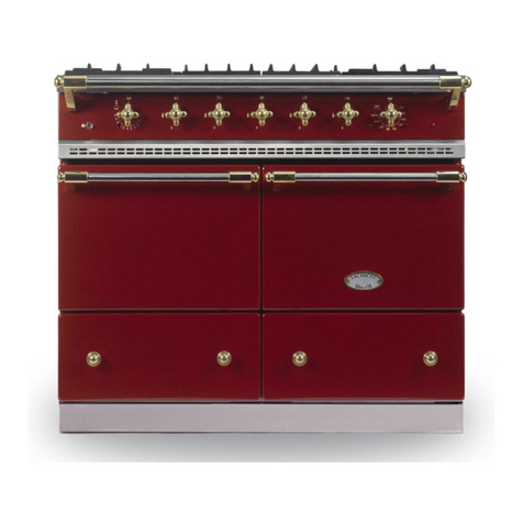
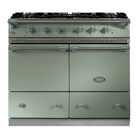
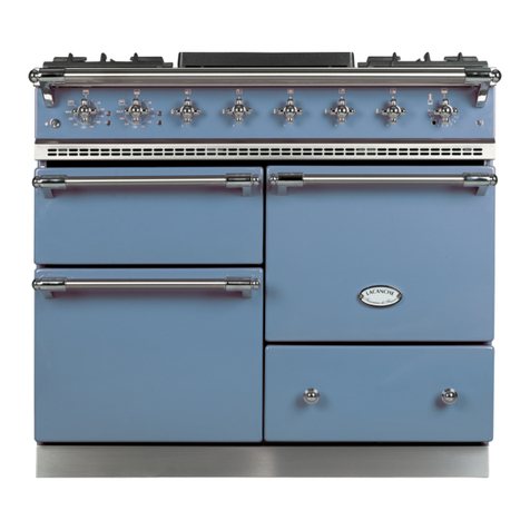
Lacanche CLUNY INDUCTION User manual

LVI 1052 EE/ ECT - G/ D
Lacanche Range Cooker
CLUNY INDUCTION
Cluny induction - Ft 151a - GB - Rév 05 - Modifié le : 07/10/2013 1/31

TECHNICAL DATA
—————————————————————————————————————————3
INSTALLER’S MANUAL 5
INSTALLATION / POSITIONING
—————————————————————————————————————————7
OPENING AND CLOSING THE HOB
—————————————————————————————————————————9
ELECTRIC CONNECTION
—————————————————————————————————————————10
SERVICING / REPAIRS
—————————————————————————————————————————11
ELECTRIC CIRCUIT DIAGRAMS
—————————————————————————————————————————15
USER’S MANUAL 17
CLUNY INDUCTION
—————————————————————————————————————————18
CAUTION
—————————————————————————————————————————19
INDUCTION HOB
—————————————————————————————————————————21
RECOMMENDATIONS BEFORE USING OVENS
—————————————————————————————————————————25
STATIC ELECTRIC OVEN
—————————————————————————————————————————27
CONVECTION ELECTRIC OVEN
—————————————————————————————————————————28
CLEANING AND MAINTENANCE
—————————————————————————————————————————29
Information regarding the elimination of electric and electronic waste
—————————————————————————————————————————31
CONTENTS
CLUNY INDUCTION
Cluny induction - Ft 151a - GB - Rév 05 - Modifié le : 07/10/2013 2/31

INSTALLER’S MANUAL
TECHNICAL DATA
500
B
A
B
C C
900
1000
527
725
650
150
894
Electric connection, on terminal block at the rear of the appliance
CLUNY ELECTRIC : INDUCTION HOB
►CLUNY INDUCTION
- 5 induction zones of different sizes and power
under a 4 mm glass-ceramic surface (Hob A, B, C
table 2 in appendix 0).
- 9 power selections
- “Booster” function on each induction zone.
- Programmable temperature setting.
- Keep Warming functions : 42°C and 70°C.
- Classic Lacanche knob hob controls.
- Digital power display.
- Child safety function
- Safety warming display when ceramic hob is hot
(above 60°C)
Power : 8900 W – 230 V 1N~ 50 Hz/
400 V 3N~ 50 Hz
The height of the cooker is adjustable between 900 and 916 mm.
► Front body panels : Stainless steel.
► Hob : Pressed stainless steel.
Cluny induction - Ft 151a - GB - Rév 05 - Modifié le : 07/10/2013 3/31

INSTALLER’S MANUAL
Static Electric Oven :
► Enamelled sheet metal.
► Dimensions L x H x P : 400 mm x 305 mm x 405 mm, 55 litre.
► 3 shelf levels with 70 mm spacing in between.
► Thermostatically controlled roof (700 W) and base (1500 W) heating elements, safety thermostat.
► Fifted with an electric grill (2100 W).
Power : 2200 W – Supply 230 V 1N~ 50 Hz
Convection Electric Oven :
► Enamelled sheet metal.
► Dimensions L x H x P : 400 mm x 305 mm x 405 mm, 49 litre.
► 3 shelf levels with 70 mm spacing in between.
► The oven is heated by a circular 2650 W element in the back wall, surrounding a fan unit.
► Thermostatically controlled roof and base heating elements, safety thermostat.
► Fifted with an electric grill (2100 W).
Power : 2650 W – Supply 230 V 1N~ 50 Hz/ 400 V 3N~ 50 Hz
Simmer oven :
►Enamelled sheet metal.
►Dimensions L x H x P : 325 mm x 495 mm x 530 mm, 85 litre.
► 4 shelf levels with 125 mm spacing i between.
►Thermostatically controlled base heating element (950 W).
►Capacity : 72 plates of Ø 24 cm.
Power : 950 W – Supply : 230 V 1N~ 50 Hz
Accessories :
Electric Oven : One roasting tray.
One grill insert with ts into the roasting tray.
One oven rack.
Directives :
Low Voltage : 2006/95/CEE.
CEM : 2004/108/CEE.
TECHNICAL DATA
Cluny induction - Ft 151a - GB - Rév 05 - Modifié le : 07/10/2013 4/31

Lacanche Range Cooker
CLUNY
INDUCTION
INSTALLER’S MANUAL
Appliances must be installed in a workmanlike manner in accordance with the instructions in this manual
and locally applicable regulations.
This manual should be handed over to the user after installation.
Cluny induction - Ft 151a - GB - Rév 05 - Modifié le : 07/10/2013 5/31


INSTALLER’S MANUAL
CAUTION :
The purchaser undertakes to install or arrange for his/her equipment to be installed in a
workmanlike manner and in accordance with the applicable regulations and standards.
Any servicing or repair work on this appliance must be performed by a qualied engineer.
Never attempt to lift the cooker by holding the hand rails. This will damage the cooker and
invalidate the warrantly.
DELIVERY & PACKAGING
The Cooker is packed in a cardboard carton, and sits on a wooden pallet to which the cooker is
bolted. You will need a 10mm spanner to undo the nuts and bolts attaching the cooker to the pallet.
Carefully remove the cooker from the pallet. NOTE: Never attempt to lift the cooker by holding the
hand rails. This will damage the cooker and invalidate the warranty.
Unpack and check the range is in good condition. In case of damage, note any reservations on the
delivery note and confirm them within 48 hours by registered letter with confirmation of delivery to
the carrier.
PLACING THE COOKER
Allow a minimum clearance of 50 mm between the appliance and any other surfaces (walls affected
by heat).
Line the cooker up with the intended space for it and gently push the cooker backwards into position,
ensuring not to mark or damage the floor. It may be helpful to cover that part of the floor over which
the cooker is to be moved with some sort of covering to protect it, which can be removed once the
cooker is in place.
LEVELLING THE COOKER
In order to level the cooker the plinth needs to be removed. This is done by removing the drawer.
Remove the drawer by opening it, and gently tilting the open front upwards and then lifting the drawer
and rear as well and extracting the drawer. Place the drawer carefully on a protective surface.
Two steel pins attach the plinth to the base of the cooker, running through the top of the plinth and
base of the cooker. These are evident once the drawer has been removed (they look like the top of
nails). Simply pull the two pins out, and carefully remove the steel plinth which should now be loose.
Using the spanner (supplied with cooker in the drawer), the rear and the front of the cooker need to
be leveled in the following way: two bolts will now be evident (exposed by the removal of the plinth).
By winding them clockwise the cooker can be lowered, by winding them anti-clockwise it may be
raised. The left bolt adjusts the rear left corner of the cooker; the right bolt adjusts the rear right of the
cooker. To adjust the front of the cooker, use the larger head of the spanner provided to turn the front
left and front right feet of the cooker, situated just inside the front edge of the corners. Clockwise
lowers the feet, anti-clockwise raises the feet.
BUILDING IN GUIDANCE
→ If the appliance is to be built in between two surfaces, it is CRUCIAL to allow free circulation of
air behind the appliance (provide shielding at rear). Cooktops should NEVER be installed lower
than adjacent worksurfaces. It is also recommended to allow the unit front panel to protrude 50 mm
relative to the adjacent units.
→ The cooker muste be installed under an exhaust hood.
→ Do not install this unit near combustible walls, partitions, pieces of furniture or decorative material
unless these are covered with adequate thermal insulation of a noncombustible type. Make sure the
resulting installation meets local re regulations.
INSTALLATION / POSITIONING
Cluny induction - Ft 151a - GB - Rév 05 - Modifié le : 07/10/2013 7/31

INSTALLER’S MANUAL
①②
① ②
INSTALLATION/ POSITIONING
◊ Use of the back in ll panel :
This feature is particularly recommended for built-in ovens as it ensures a 50 mm gap between the
appliance and the wall. It also increases the depth of the hob to 722,5 mm.
Product code : DS 1000.
A shut-off valve must be install and accessible close to the appliance in order to isolate it from the
gas applicable or to facilitate cutting the gas supply :Please ensure that installation complies with
local applicable regulations and standards
- Natural gas supply :
Mandatory to install an Automatic Shut-off Valve (since 1st July 1997 in France)
- LPG supply (butane, propane) :
Propane : Class 1 Safety Expansion Valve.
Butane : Butane safety expansion valve tted to the cylinder (connected to the range by a LPG
approved hose, maximum length 2 metres).
We recommend the front edge of the hob be positioned 50 mm further forward than the adjacent
ttings.(see below).
If the adjacent parts contain heat-sensitive materials, ensure there is a 50-mm gap between the
side of the oven and the parts in question.
Ensure that the materials adjacent to the lateral panels of the oven are not
ammable.
Back in ll panel
Cluny induction - Ft 151a - GB - Rév 05 - Modifié le : 07/10/2013 8/31

INSTALLER’S MANUAL
To remove top :
1- Loosened the 2 screws (see
A
/ figure 1)through the ventilation strip.
2. Lift the hob (figure 2).
3- Wedge the hop open (see.
B
/ figure 2).
OPENING AND CLOSING THE HOB
A
1
2
B
1.Pull foward
2. Lift the table
Retting the cooking surface
When refitting the cooking surface, it is vital to tighten the fastening screws. Failure to do so can
cause distortion of the hob top.
It may be necessary to open the hob under the following circumstances :
- Making adjustments when changing gas type.
- Adjusting thermocouples.
- Resetting the safety thermostat.
Cluny induction - Ft 151a - GB - Rév 05 - Modifié le : 07/10/2013 9/31

INSTALLER’S MANUAL
The cooker must be installed in a workmanlike manner in accordance with the instructions in
this manual and locally applicable regulations. This manual will be handed over to the user after
installation.
Before connection, check :
That the electrical supply of the system is compatible with the voltage and power of the range.
The user’s xed installation must include an all-pole circuit-breaker of approved type.
Connection : CAUTION :
- Cable insulation must be type 245 IEC 57 or 245 IEC 66
- The length of the conductors of the power cable between the strain relief device and the terminals
must be such that the conductors become taut before the earth conductor in case of traction on
the cable.
- If this unit is permanently connected to a xed electrical cable, the cable should be equipped with
a fault leak protector.
- If this unit is connected to a wall outlet, the outlet should be permanently accessible.
- Remove cover ( or covers) (see A/ figure 1), to the back of the unit identified by .
- Use a standard flexible cable to connect to terminal block (see B/ figures 1& 2).
- Secure the cable by means of cable clamp (see C/ figure 1).
It is hazardous to put the appliance into service without connecting it to suitable ground.
ELECTRIC CONNECTION
L N
1 2
400 V 3N ~ 50 Hz 230 V 1N ~ 50 Hz
230 V 1N ~ 50 Hz 230 V 3 ~ 50 Hz
L1 NL2 L3
1 2 3 4 5
N L1 L2 L3L
1 2 3 4 5 1 2 3 4 5
The supply of three phase 400 without neutral is not possible
No liability can be accepted for accidents resulting from non-compliance with this
requirement or incorrect grounding.
1
2
A
C
B
D
Cluny induction - Ft 151a - GB - Rév 05 - Modifié le : 07/10/2013 10/31

INSTALLER’S MANUAL
SERVICING / REPAIRS
To reset limiting thermostat
The button is behind the ventilation strip . To have access there, it is necessary to use a small
screwdriver to press on the push-button and reset limiting thermostat (see A, figure 1).
CAUTION :
Do not obstruct the vents.
When installing ensure there is a 50 mm gap between the partition and appliance to enable the
induction plate to cool down correctly.
All work on or repair of an appliance must be carried out by a qualied engineer.
Before any work is carnied out on the appliance it must be disconnected from the main electricity
supply by disconnecting the terminal strip located on the back of the unit.
Limiting thermostat :
In accordance with the construction regulations, the limiting thermostat is intended to protect the
range from overheating.
In the event of overheating the limiting thermostat is triggered and cuts out the range’s oven
functions.
The advanced technology used in the limiter means that it is very sensitive to impacts and vibration
1
A
Cluny induction - Ft 151a - GB - Rév 05 - Modifié le : 07/10/2013 11/31

INSTALLER’S MANUAL
Encoders :
But before doing this the module must be disconnected from the terminal strip located on the back
of the unit (see A, figure 1).
To access the encoders, remove the top. (See «To remove top»).
Remove the control knop, by pulling off.
Disconnect the electric cable from the induction hob to the encoder (see B, figure 2).
Unscrew the two screws, (see C, figure 3) securing the encoder to the control panel.
Remove the encoder and replacewith the new one.
Replace the components, in reverse order.
Encoder reference : 65 225006
SERVICING / REPAIRS
1
A
B
Induction unit :
But before doing this the module must be disconnected from the terminal strip located on the back
of the unit (see A, figure 1).
To access the induction unit, remove the top (See «To remove top»).
Disconnect all the cable for the induction hob to the terminal blocks and the encoders cable (see
A, figure 1).
Remove the hob and rest it on a stable surface. Ensure the vitroceramic hob is placed on a clean,
soft surface so that the glass top is not scratched (see figure 4).
3
C
2
Cluny induction - Ft 151a - GB - Rév 05 - Modifié le : 07/10/2013 12/31

INSTALLER’S MANUAL
SERVICING / REPAIRS
Unscrew the screws from the induction heaters (use a screwdriver or a T10 TORX key), (see D,
gure 4and 5) .
Hold induction units against the vitroceramic and return the complete hob
Unscrew all the screws maintaining the induction units to the vitroceramic,
(see E gure 6and 7).
Remove the vitroceramic hob. The induction units are now open and you
can see the different rings (see gure 6). Dévisser les vis Epour libérer
les foyers.
To replace, do the same thing in reverse order.
Caution: Be sure the rings do not move when xing the induction units to
the vitroceramic.
DD
D
45
6
E
7
E
Cluny induction - Ft 151a - GB - Rév 05 - Modifié le : 07/10/2013 13/31


INSTALLER’S MANUAL
For references and descriptions of the various components refer to table 9 in appendix 0
ELECTRIC CIRCUIT DIAGRAMS
LE
N2N1
L3L2L1
P2
P1
P3
4
3
1
2
5
H4 H1
TH
TL
SCE1_005/A
L
Mr
X1
S
R14
R16
1 2 3 4 51 2 3 4 51 2 3 4 5
L1 L2 L3 N
400 V3N~
230 V3~
1 2 3 4 5
L1 L2 L3
1 2 3 4 51 2 3 4 51 2 3 4 5
L1 L2 L3
X
Induction Hob
Static Electric Oven
Cluny induction - Ft 151a - GB - Rév 05 - Modifié le : 07/10/2013 15/31

INSTALLER’S MANUAL
ELECTRIC CIRCUIT DIAGRAMS
LE
N2N1
L3L2L1 N2N1
L3L2L1
P2
P1
P3
4
3
1
2
5
SCE1_007/A
H4 H1
TH
TL
L
Mr
X1
S
R15
M
R14
Convection Electric Oven
Cluny induction - Ft 151a - GB - Rév 05 - Modifié le : 07/10/2013 16/31

Lacanche Range Cooker
CLUNY INDUCTION
USER’S MANUAL
IMPORTANT
It must be installed in accordance with the applicable regulations and standards in an adequately
ventilated room.
Any changeover to a gas other than that for which the cooker is set up must be carried out by a qualied
installer.
Any changeover to a voltage other than that for which the cooker is set up must be carried out by a qualied
engineer.
WARRANTY
The warranty is stated on the sales contract. Please contact your approved Dealer if any work has to be
carried out under warranty.
This warranty excludes damage resulting from incorrect installation, improper use or inadequate servicing.
Cluny induction - Ft 151a - GB - Rév 05 - Modifié le : 07/10/2013 17/31

This range has the marking, i.e. it meets the essential requirements of the Euro-
pean safety directives to which it is subject.
CAUTION
—————————————————————————————————————19
INDUCTION HOB
—————————————————————————————————————21
RECOMMENDATIONS BEFORE USING OVENS
—————————————————————————————————————25
STATIC ELECTRIC OVEN
—————————————————————————————————————27
CONVECTION ELECTRIC OVEN
—————————————————————————————————————28
CLEANING AND MAINTENANCE
—————————————————————————————————————29
Information regarding the elimination of electric and electronic waste
—————————————————————————————————————31
USER’S MANUAL
CLUNY INDUCTION
Cluny induction - Ft 151a - GB - Rév 05 - Modifié le : 07/10/2013 18/31

USER’S MANUAL
This appliance is not for use by children. If unfamiliar with this appliance, use should
be overseen by a competent person who has read all the relevant information.
Before use, it is mandatory to remove all the internal and external plastic packing,
failure to do so will cause irreversible damage to the steel walls of the cooker.
Never store flammable products in the oven, cabinet, plate-warmer or on the table.
Flammable materials can catch fire, plastic items may melt or ignite and other
types of items could be ruined items in other materials may be damaged.
Never hang / store any ammable products above the appliance, to avoid risk of
re.
The oor covering of the room in which the range is to be tted must be capable
of withstanding temperatures 65°C greater than ambient temperature without
distorting, shrinking or fading. This range must not be tted on a carpet or plastic
oor covering.
Do not obstruct the flow of combustion or ventilation air to the appliance. Be sure
a fresh air supply is available.
Do not use aluminum foil to line any part of the oven or on the hob.
Do not hang articles from any part of the appliance or place anything against the
oven to avoid risk of re or degradation of material (e.g.melting).
This appliance is for cooking. Based on safety considerations, never use the oven
or hob to warm or heat a room. Also, such use can damage the hob or oven parts.
Do not hang articles from any part of the appliance or place anything against the
oven to avoid risk of re or degradation of material (e.g.melting).
When using the hob, do not touch the burner grates or the immediate surrounding
area. Areas adjacent to the burners may become hot enough to cause burns.
When using the cooker, accessible parts may be hot. It is recommended children
stay strictly away from the cooker at all times.
Monitor the children to be sure they don’t play with the cooker.
Children should not be left alone in the kitchen while the range is in use. Do not
store items of interest to children over the unit. Children climbing to reach items
could be seriously injured.
When using the oven, do not touch the interior surfaces of the oven, the exterior
area immediately surrounding the door. The range gets hot during use. Do not
touch heating elements inside the oven.
Disconnect from power supply before servicing.
If appliance is installed on a base, take precautions to prevent appliance sliding
off the base.
After any use, to close the valve and cut off gas supply.
Always be sure to disconnect the cooker from the mains electricity supply when
replacing the oven light.
This appliance is not made to be used in conjunction with any type of external
timer or separate control system
Never attempt to lift the cooker by holding the hand rails. This will damage the
cooker
CAUTION
Cluny induction - Ft 151a - GB - Rév 05 - Modifié le : 07/10/2013 19/31

Table of contents
Other Lacanche Cooker manuals

Lacanche
Lacanche CORMATIN LG 731 G User manual

Lacanche
Lacanche Cluny 1000 User guide

Lacanche
Lacanche RULLY User manual

Lacanche
Lacanche SULLY CHALONNAIS LG 1432 GE User guide

Lacanche
Lacanche CITEAUX INDUCTIONLVI 1532 E / CT User manual

Lacanche
Lacanche LAE 020 I User manual

Lacanche
Lacanche Classic User manual

Lacanche
Lacanche RULLY User guide

Lacanche
Lacanche MACON Configuration guide

Lacanche
Lacanche CLUNY User manual