manuals.online logo
Brands
  1. Home
  2. •
  3. Brands
  4. •
  5. Lafferty
  6. •
  7. Industrial Equipment
  8. •
  9. Lafferty 910310 Installation instructions

Lafferty 910310 Installation instructions

Other Lafferty Industrial Equipment manuals

Lafferty VC-1016 Installation instructions

Lafferty

Lafferty VC-1016 Installation instructions

Lafferty VC-1016 Installation instructions

Lafferty

Lafferty VC-1016 Installation instructions

Popular Industrial Equipment manuals by other brands

ABB +Q957 user manual

ABB

ABB +Q957 user manual

G.B.C BASIC EDGE 50 instruction manual

G.B.C

G.B.C BASIC EDGE 50 instruction manual

Tronair Batpak 11-6602-1000 Operation & service manual

Tronair

Tronair Batpak 11-6602-1000 Operation & service manual

Pilz PNOZ mi2p Operation manual

Pilz

Pilz PNOZ mi2p Operation manual

Clemco Zero BNP 6012 manual

Clemco

Clemco Zero BNP 6012 manual

Erskine Attachments V-Plow Operator's manual

Erskine Attachments

Erskine Attachments V-Plow Operator's manual

ABB HT610965 Operation manual

ABB

ABB HT610965 Operation manual

Morra MH 540 user manual

Morra

Morra MH 540 user manual

Eaton S090ST manual

Eaton

Eaton S090ST manual

GRIGGIO G 240 P4 instructions

GRIGGIO

GRIGGIO G 240 P4 instructions

Nexen AIR CHAMP HT45 user manual

Nexen

Nexen AIR CHAMP HT45 user manual

WTE V5 installation manual

WTE

WTE V5 installation manual

ABB HT845232 Operation manual

ABB

ABB HT845232 Operation manual

SMC Networks CJP Series Operation manual

SMC Networks

SMC Networks CJP Series Operation manual

JohnDow Industries JDI-AFT58 Operator's manual

JohnDow Industries

JohnDow Industries JDI-AFT58 Operator's manual

IMB MB9016A instruction manual

IMB

IMB MB9016A instruction manual

Clarke CUMB1 Assembly & operating instructions

Clarke

Clarke CUMB1 Assembly & operating instructions

amiad Arkal Spin Klin 2 user guide

amiad

amiad Arkal Spin Klin 2 user guide

manuals.online logo
manuals.online logoBrands
  • About & Mission
  • Contact us
  • Privacy Policy
  • Terms and Conditions

Copyright 2025 Manuals.Online. All Rights Reserved.

Lafferty Equipment Manufacturing, Inc.
Installation & Operation Instructions
Model # 910310 · Triple Foam Stick Set
# 475200FT
# 475400FT
# 475300FT
# 491456-E
REQUIREMENTS
Ready to Use Chemical Solution
Solution Pressure 40 - 60 PSI
Flow Rate up to 1.55 GPM
Compressed Air up to 1.5 CFM
Liquid tubing - pump to tee 1/2" I.D.
Liquid tubing - tee to foam sticks 3/8" I.D.
Tubing from air supply 1/4" I.D.
OPTIONS
Air and Chemical Tubing (Order in 10' Increments)
Air, Polyflow, 1/4" x 1'
Solution, Pump to Tee, Polyflow, 1/2" x
1'
Solution, Tee to Foamer, Polyflow, 3/8"
x 1'
Alternate Check Valve (Viton Standard)
TL Check Valve, PVC / EPDM, 3/8"
WEIGHT & DIMENSIONS
Single Package
Shipping Weight 19 lbs.
Shipping Dimensions 91" x 8" x 5"
Additional Package
Shipping Weight 19 lbs.
Shipping Dimensions 91" x 8" x 5"
www.laffertyequipment.com
501-851-2820
OVERVIEW
The Triple Foam Stick Set is a foam applicator designed for car-wash pre-soak, brush lubrication or to apply any 3 foaming products. This unit receives 3 ready-to-use
chemicals from a pumping system and injects compressed air to increase the solution volume and create thick, rich, clinging foam. The foam is then evenly projected
through the 7 foot foam stick assemblies. A fixed flow rate allows the user to use just one air valve to adjust the foam quality for all 3 foam sticks simultaneously. This
system is great for retrofitting and for new installations.
W AR N I N G ! R E A D A L L
I N S T R U C T I O N S B E F O R E
U S I N G E Q U I P M E N T !
Lafferty Equipment Manufacturing, Inc. • 5614 Oak Grove Road • North Little Rock, Arkansas 72118
SAFETY & OPERATIONAL PRECAUTIONS
For proper performance do NOT modify, substitute nozzle, hose diameter or length.
Manufacturer assumes no liability for the use or misuse of this unit.
Wear protective clothing, gloves and eye-wear when working with chemicals.
Always direct the discharge away from people and electrical devices.
For pressures over 100 PSI, remove the discharge valve or lower pressure
Follow the chemical manufacturer’s safe handling instructions.
Turn off solution supply and air when unit is not in use for extended periods.
TO INSTALL (REFER TO DIAGRAM ON NEXT PAGE)
1. Remove the tube lock check valves from the enclosed bag and install as shown in the drawing.
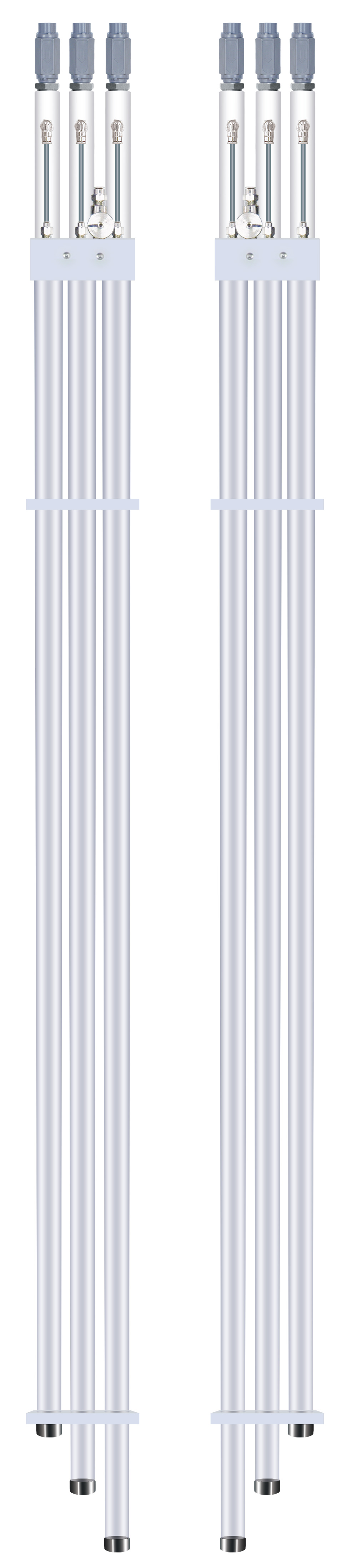
2. Mount each of the triple foam sticks to either side of the bay. The longest bar should be mounted so that its foam is the first to contact the vehicle. They should be mounted so
that the last hole (in the cap) hits the bottom of the vehicle. The stick sets should be "mirror-images" of each other once mounted.
3. Run 1/2" I.D. chemical tubing from each of the three "solution pumps" to the middle of the arch and connect with a tubing tee (not included).
4. From there step down to 3/8" I.D. tubing and connect to the solution check valves. The tubes should be the same length for the best performance.
5. Run 1/4" air tubing from your compressed air supply to the middle of the arch and push connect it to the 1/4" tube lock of the tee. (not included)
TO OPERATE
1. As a starting point turn the air needle valve on each stick set completely clockwise, then open it 1/2 turn counterclockwise.
2. Activate the solution and air pressure. Wait a few seconds to purge the air out of the solution tube and for the solution to get to the foamers. Solution pressure must be between
40 - 60 PSI. Air pressure/volume is controlled by the needle valves.
3. If the foam isn't acceptable, turn the needle valve slightly counterclockwise for dryer foam and slightly clockwise for wetter foam. If the needle valve is open too much, the foam
will be pushed past the first holes and air only will blow out the fist hole or two. If this happens, turn the needle valve slightly clockwise until all the holes are foaming. Once the
sticks are foaming properly, no further adjustment should be needed. You are ready for operation.
910310 • Triple Foam Stick Set
- Page 2 -
910310 • Triple Foam Stick Set
- Page 3 -
Troubleshooting Guide
Problem Possible Cause / Solution
Startup Maintenance
A) Foam surges or sputters.
B) Foam too dry.
C) Foam too wet.
D) Solution drips after shutting down.
1, 2, 3, 4, 5
1
1, 3, 4, 5
6, 7, 8
6
6
Possible Cause / Solution
Startup Maintenance
1. Air volume too high or too low
Adjust the needle valve very slightly counterclockwise
for dryer and clockwise for wetter. VERY little air is
needed, if the top hole is sputtering you have too much
air on them, turn needle valve knob slightly clockwise
until all holes produce foam.
2. Use of an oiler in the airline will cause poor foam quality
Use only clean, dry air.
3. Solution Pressure too Low
Must be 40 PSI minimum. 60 PSI maximum
4. Not enough chemical.
Increase concentration.
5. Discharge tubes kinked or wrong size.
Straighten the tubes or replace with correct size.
6. Solution Chemical check valve stuck or failed.
Clean or replace.
7. Leak in air or solution connections.
Tighten the connection or cut off 1/2" of tube and
reconnect.
8. Needle valve clogged not allowing enough air
Clean or replace.
9. Chemical build-up may have formed in the foamer causing
low flow
When there is no flow at all, carefully remove fittings
and soak entire foam wand in descaling solution. Or
replace.
PREVENTIVE MAINTENANCE: When the unit will be out of service for extended periods, place chemical tube(s) in water and flush the chemical out
of the unit to help prevent chemical from drying out and causing build-up. Periodically check and clean chemical strainer and replace if missing.
910310 • Triple Foam Stick Set
March 11th 2021 - Page 4 -