7
System Maintenance
Standard Dry Run Thermostat Operation
Each SM(T)-303 and UC(T)-303 model pump has a built-in 200ºF thermal cut-off in order to protect
against overheating, which could cause damage to the pump motor. In the event that disruption of your
immediate hot water supply is noticed it is possible that the pump has or is running dry and the internal
dry run thermal protector has shut down the pump motor. In this event, it is important that the dry run
condition be corrected (otherwise the pump will fail prematurely) by following the procedure below:
1. Disconnect power to the pump motor.
2. Close the shut-off valves on each side of the pump.
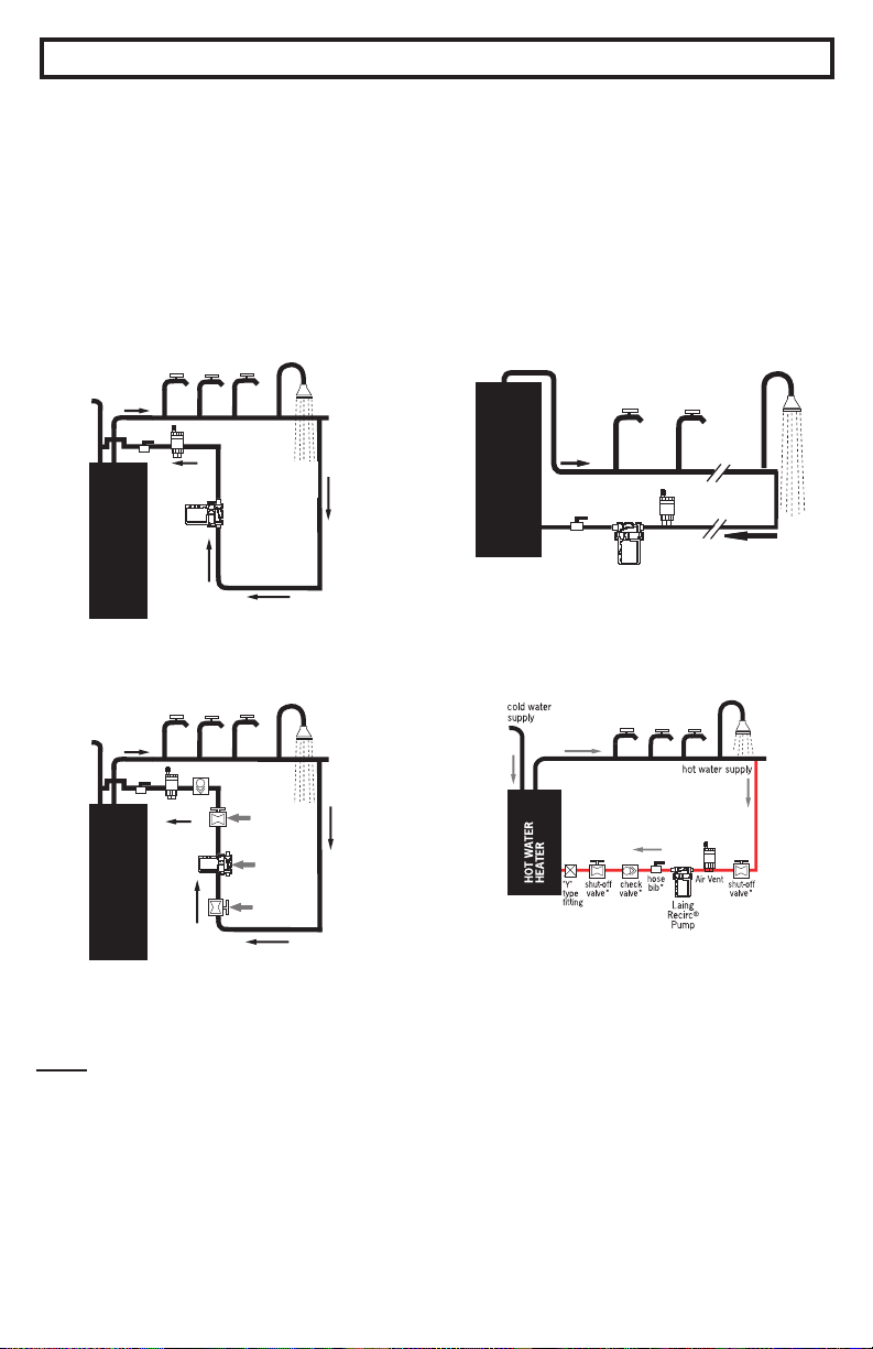
3. Remove the pump motor/rotor assembly from the pump housing.
4. Dry off the pump motor/rotor assembly. Remove the rotor and check for any calcium build-up,
foreign matter or any signs of wear. If these signs are not present, put the rotor back in place on the
ceramic ball.
5. Hold the pump motor/rotor assembly upright and plug in the unit for about 10 seconds to see if the
rotor spins evenly and quietly. If the motor does not go on, allow a few more minutes for the thermo-
stat to reset as the unit cools down.
6. If the rotor spins properly, unplug the motor and reinstall the assembly into the pump housing.
7. Turn both shut-off valves to the on position, reconnect the electrical supply to the pump motor, and
be sure that air is properly purged from your system.
130ºF On-Off Thermostat Option “C”
Pumps with the letter “C” in the model are provided with a factory option “C” internal thermal cut-off which
automatically shuts the pump down when the temperature of the water passing through the pump housing
reaches 130ºF +/- 10ºF and turns the pump on at 110ºF +/- 10ºF (SM/SMT 909-14 only).
Variable Setting On-Off Thermostat Option “R”
Pumps with the letter “R” in the model designation are provided with a factory installed internal
thermal cut-off with an adjustable On-Off temperature dial located on the outside of the motor. This
dial can be rotated by placing a thin screw driver in the dial slot which allows the pump to turn off
automatically when the water temperature passing through the pump housing reaches the dial setting
selected-between 95ºF and 140ºF. The pump will turn back on automatically when the water tem-
perature cools down to 10ºF below the set temperature (SM/SMT-303 only).
• Do not attempt to lubricate
the pump. The pump is self-
lubricating.
• Prevent the pump from run-
ning dry.
• Flush the system of any de-
bris and re-purge all air from
the system in the event of any
water supply interruptions in
plumbing line.
• Prevent heavy scale build-up
by keeping the hot water
temperature 140ºF or less.
• Don’t over salt your water
conditioner.
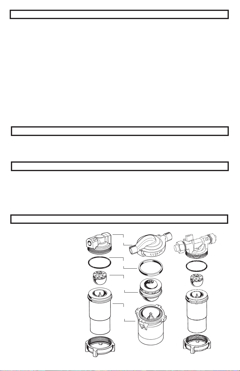
Replacement Parts
Please provide the following
information
when ordering:
• Model number
• Serial number
• Part description
6
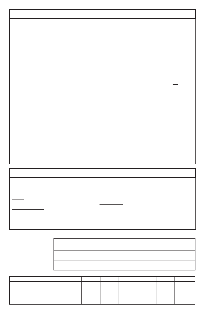
Do
• install an air vent mounted in a vertical position (if provided).
• use 1/2” recirculation line tubing.
• check to be sure there are no crimps or sharp bends in the recirculation line that would restrict the ow.
• be sure the check valve is installed in the proper direction of the ow.
• be sure all air is purged from the system prior to starting the pump.
• use a water conditioner if you have hard water.
• be sure the gate valves are open before turning on the pump.
• install the pump pumping in upward direction only.
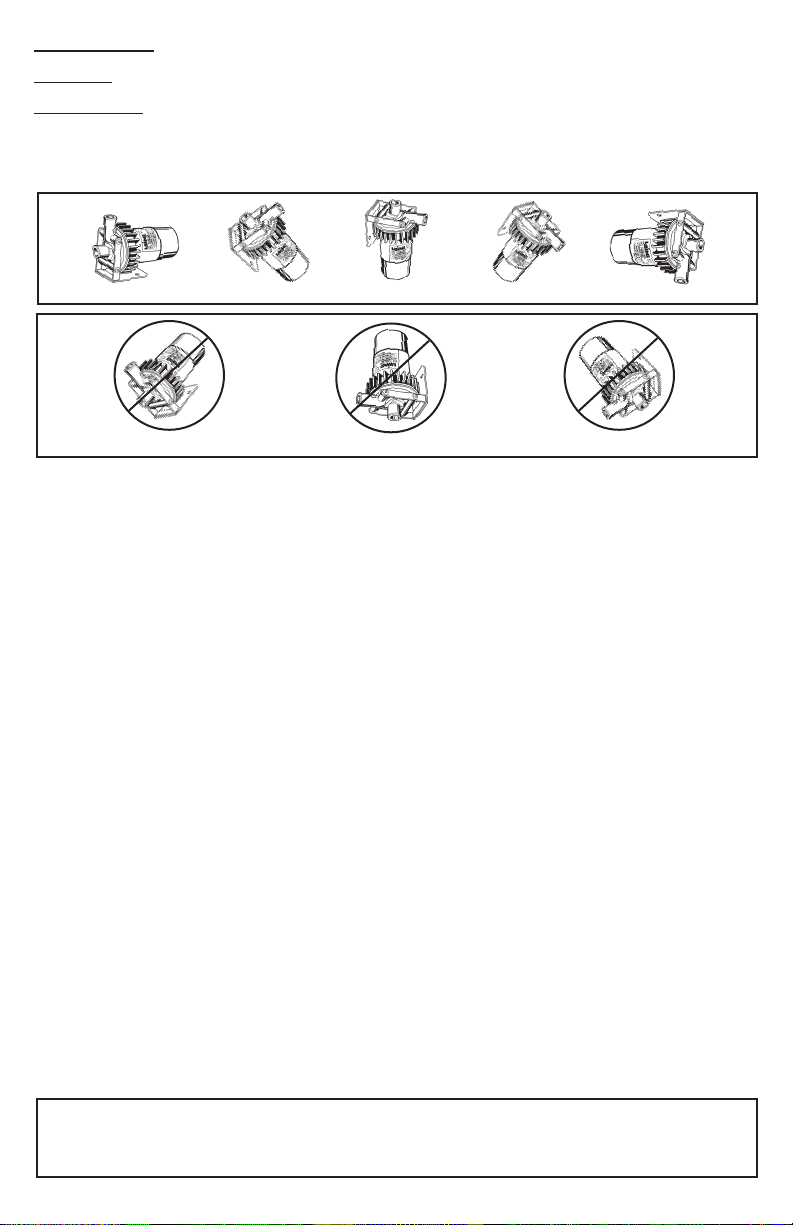
Do Not
• use grease or oil to lubricate the pump - it is self-lubricating.
• over tighten the screw ring (SM-303 models).
• install the pump with the motor above the pump housing.
• install the pump pumping away from the water heater nor pumping downward.
• start the pump before the system is full of water and purged of air.
• allow the water heater temperature above 140ºF.
• install the pump in the supply line to faucets.
• use any pipe size other than 1/2” for SM-303 or UC-303 models.
• position the pump at the top of the water heater.
Notes:
Keep The Hot Water Temperature Below 140ºF: Higher temperatures can cause calcium and mag-
nesium elements to come out of solution and create solids which could not only cause damage to the
pump but also reduce water heater efciency and premature failure of the water heater.
Hard Water Conditions: Use a water conditioner. Hard water can cause scale build-up and eventually
reduce the life of the pump and other system components.
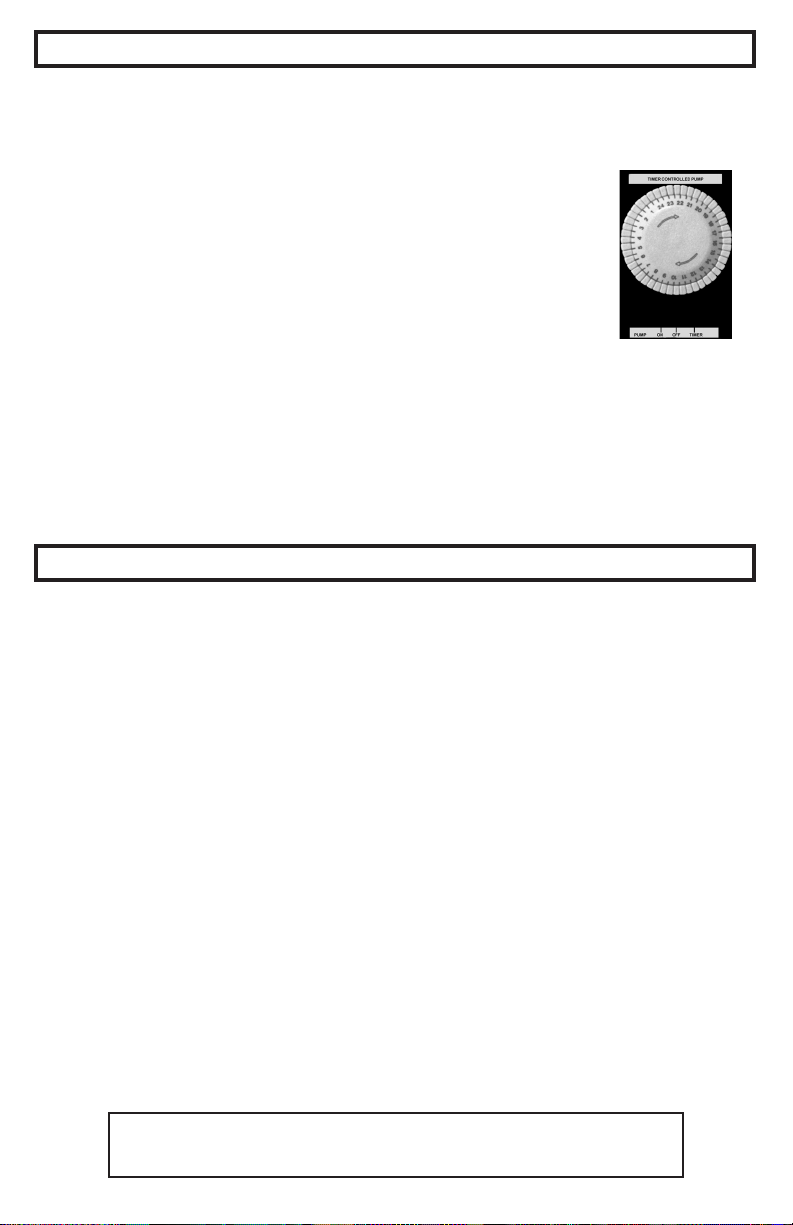
If timer controlled operation is desired, the timer may be programmed to allow the Autocirc
to operate during the hours desired (i.e. “ON” from 7:00 a.m. to 9:00 p.m. and “OFF” from
9:00 p.m. to 7:00 a.m.) as follows:
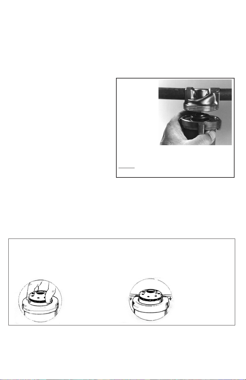
• Open timer cover and rotate the dial clockwise until the cor-
rect time is aligned with the pointer () on the right side (3
o’clock position) of the dial. A timer instruction label afxed to
the right side of the timer housing also shows this time setting
point.
• Automatic Operation: PULL the tabs Upward on timer for the
desired operating period of time. Example: If the desired
operating time is 7:00 a.m. to 9:00 a.m., all tabs should be
Pulled out between 7 and 9. NOTE: The timer may be set for
multiple operating periods of time.
• Slide the switch bar to “timer”.
The timer mode will provide the most cost effective method of operation and can be pro-
grammed to run only during the time periods when hot water is most frequently required.
Even during controlled timer operation, the Autocirc will only turn on when the built-in
thermostat senses that additional hot water is required at the point of installation.
Protected by one or more of the following Patents:
4580335, 4615662, 4822256, 4834628,
5094593, 5143049, 5749715, 6149407, 6227235
Do’s and Do Not’s
Timer Controlled Operation
SM-303-B SM-909-B-14
Housing
“O” Ring
Rotor
Assembly
Motor
Assembly
Screw
Ring
UC-303-B
Housing
“O” Ring
Rotor
Assembly
Motor
Assembly
Screw
Ring
30 Min. Tabs