LAISAI LS526 User manual

Dear User,
Thank you very much for choosing LAISAI LS526/LSG526 rotary aser, p ease read this instruction manua before
operating it.
Content
1. Features and functions
2. User safety
3. Nomenc ature
4. Operation instruction
5. Se f-check and ca ibration
6. App ication demonstration
7. Technica specification
8. Maintenance
1. Features and functions
LS526 (red aser)/LSG526 (green aser) fu automatic rotating aser can project se f- eve ing horizonta aser p ane and
p umb up ine, and vertica aser p ane and horizonta ine. It supp ies accurate horizonta reference for working
construction ay out and ca ibration indoor and outdoor. It is convenient for operation and wide y used.
Features:
※
E ectronic auto- eve ing, when beyond the range, the instrument stops rotating and sound indication.
※360° rotary aser, ab e to work horizonta y and vertica y
※
Ab e to set different rotation speed and area scanning ang e
※
Ab e to unba ance a arm in TILT mode. The instrument stops rotating when knocked, in order to make sure work
accurate y.
※
S ope mode function cou d set sing e axis or doub e axis s ope
※
Accuracy se f-ca ibration function
※
Timing power-off function
※
Remote operation function
※
Ab e to connect with tripod through 5/8’’ thread.
※
Rainproof and dustproof
2. User safety
※
Laser output sign ies near the output aperture.
※
Do not stare into aser beam direct y.
※
Do not disassemb e the instrument or attempt to perform any interna servicing. Repairs and servicing cou d be
performed on y by authorized service centers.
※
The instrument comp ies with the safety c assification standards of aser radiation.

3. Instrument nomenclature
4. Operation instruction
4.1 Battery mount
a) Mount 3*C a ka ine batteries into battery box according to po arity direction, then fix the battery box on the instrument.
b) Fix the rechargeab e battery on the instrument
4.2 Charging to rechargea le attery
Centra 5/8″screw thread
Side 5/8″ screw thread
Battery cover screw
Remote receiving tube
Battery cover
Laser output window
Hand whee
Rotary head
Operation keypad

Insert the charger into charging jack, then the rechargeab e battery in charging. The indication ight is red when it is in
charging, it turns green when the battery is in fu .
Charging direct y to rechargeab e battery box direct y:
Charging to the rechargeab e battery on the instrument:
Note:
a) When the power LED is f ashing, the battery is in ow vo tage. It can extend the ife of the battery when charging the
battery as the battery is use up.
b) Charging once to rechargeab e battery every two or three months since the instrument eaving factory.
4.3 Placement of the instrument
Instrument in horizonta p acement:
a) P ace on a horizonta p atform direct y
b) Connect with the tripod through 5/8’’ thread of the bottom of the instrument.
Charging status LED

。
P ace the instrument transverse y:
a) Ab e to p ace the instrument on the horizonta p atform
b) Set on the tripod with side 5/8’’ screw thread
4.4 Instrument operation keypad
S ope move eftwards key
TILT mode key
Se f- eve ing key
X direction s ope LED
Y direction s ope LED
Remote status LED
TILT mode LED
S ope function key
Remote shie ding key
Area scanning/dot move c ockwise key
/
Area scanning/dot move anti-c ockwise key
Power LED
On/off key
Area scanning function
Rotation speed set key
S ope move rightwards key

Power LED:
Lighted LED means power-on
Extinguished LED means power-off
F ashing LED means ow battery vo tage
TILT mode LED:
F ashing s ow y (1Hz): The instrument enter into TILT preparation status
Lighted constant y: The status of TILT function become effective
F ashing quick y: The instrument is in TILT a arming status
Extinguished: The instrument exit from TILT status
Slope axis LED:
Both X and Y LEDs, the LEDs are on means this axis is in the s ope set status.
Remote control indication LED
ON: remote contro function is on, and ab e to use the remote contro to operate the instrument.
OFF: remote contro function is off, cou d on y operate the instrument with keypad
4.5 on/off key
a) Press on/off key, the instrument is power on, the power LED is ighted.
b) The instrument is in auto- eve ing status when the power is on. Then rotating in high speed after auto eve ing, the
rotating speed is 500rpm.
4.6 Rotation speed set key
After the instrument is se f- eve ing, the instrument is in high speed rotation status, the rotation speed is 500rpm.Press
rotation speed set key, the rotation speed is switched to ow speed, and the rotation speed is 200rpm.
4.7 Area Scanning function key
a) When the instrument is rotating, press this key to enter the area scan mode, the instrument enter into big area
scanning status, press this key again, enter into sma area scanning status, press this third time, enter into dot status,
the area scanning order wi be switched as fo ows,
4.8 Area scanning moving key
a)Under area scanning status, press area scanning moving key, sing e press to move s ow y, ong press to move
continuous y.
b) Under dot status, press area scanning moving key, sing e press to move s ow y, ong press to move continuous y.
4.9 TILT mode key
a) Press TILT key to exit or enter TILT mode(the instrument wi power on and enter into TILT mode automatica y).
b) After entering into TILT mode, the status LED f ash s ow y (1Hz), after eve ing, the head rotates, and TILT function is
activated after 30 seconds, the status LED is a ways on, the instrument wi sound TILT a arming once shocked, the
status LED f ash quick y, the aser stop rotating and start f ashing, the instrument wi not se f- eve ing, press TILT key
again, exit TILT status and enter into se f- eve ing status.
c) If the instrument is under doub e axis s ope working status, TILT key is inva id.
Big area scanning Big area scanning Dot

4.10 Slope function key
a) P ace the instrument horizonta y
Press s ope function key, the instrument enter into doub e axis s ope, the defau t is X axis s ope, X LED is on, Y axis is
not eve ing, press s ope eft/right moving key cou d make s ope adjustment, short press s ope function key cou d switch
X/Y direction, ong press to exit s ope function.
Long press s ope function key, the instrument enter into sing e axis s ope, the defau t is X axis s ope, X LED is on, Y axis
is se f- eve ing, Y LED f ash. Press s ope eft/right key cou d make s ope adjustment. Short press s ope function cou d
switch s ope direction X/Y, ong press to exit s ope function.
b) P ace the instrument transverse y
Press s ope function key, the instrument enter doub e axis s ope, defau t is X axis s ope, X direction LED is on, Y axis is
not eve ing, press s ope eft/right key cou d make s ope adjustment, press s ope function key cou d switch X/Y direction,
ong press to exit s ope function.
Long press s ope key, the instrument wi enter sing e axis s ope, the defau t is X axis s ope, X LED is on ,Z axis is
se f- eve ing, Y direction LED is f ash, press s ope eft/right moving key cou d make s ope adjustment, ong press to exit
s ope adjustment function.
4.11 Self-leveling key
Press this key, the instrument wi enter into se f- eve ing status, the instrument is in TILT a arming status, press this key,
the instrument exit a arming status, and make eve ing, after eve ing, TILT mode sti remains, when the instrument is in
s ope adjustment status, press this key, the instrument wi exit s ope adjustment and enter into se f- eve ing status.
4.12 Remote shielding key
Power on and the remote function is on defau t, the remote status indication LED is on, press this key, the LED is off,
the instrument wi not receive the signa of remote contro .
4.13 Remote control keypad
S eep key
a) Press s eep key, the instrument enter or exit s eep status.
b) The instrument enter s eep status, power LED f ash interva , if the instrument wi not exit s eep status in 30 minutes,
Se f- eve ing key
S ope function key
Area scanning function key
Area scanning moving key
ON/OFF key
Se f-ca ibration direction se ect key
S ope function key Rotation speed switch key
Ca ibration confirmation key
Se f-ca ibration adjustment key
Z direction
Y direction
X direction

the instrument wi power off automatica y.
The function of the rotation speed switch key, se f- eve ing key, area scanning function key and s ope function key on the
remote contro is same with the instrument.
5. Self-check and Cali ration
The instrument must be se f-checked after service for a certain time or before operation in a major project. If the
accuracy is found beyond to erance, user makes some adjustment according to methods as fo ows.
5.1 Accuracy check
X、Y accuracy check
(1) Set a p atform in a room which is 20m far way from the wa , put the instrument on the p atform, and take the X axis
face to the wa .
(2) Power on and after the instrument is auto- eve ed, mark the aser ine which is on the wa as sign A, and make a
vertica ine a ong sign A
(3) Rotate the instrument by 90 degrees in turn, after the instrument is auto eve ing, mark the point of intersection of the
aser ine and the vertica ine as point B, C and D separate y.
(4) Measure the maxima distance h between two points which among point A, B, C, D.
(5) If h≤3mm, the accuracy is OK; If 3mm< h≤20mm, the accuracy is beyond to erance, the user cou d adjust and
ca ibrate the accuracy; If h>20mm, the accuracy is beyond to erance, user must contact with se er for service
Z axis accuracy check
(1)Fo ow X, Y accuracy check figure, measure the height H from horizonta aser p ane to the p atform when p acing
the instrument horizonta y.
(2)P ace the instrument vertica y on the p atform, and take Z axis face to the wa .
(3)Power on the instrument, make the peak to project on the wa , after the instrument is eve ing, mark E.
(4)When p acing the instrument transverse y, measure H2 from the aser dot to the p atform, ca cu ate H va ue
H
1
Z direction
X direction
Y direction
Z direction
Y direction
X direction
H1

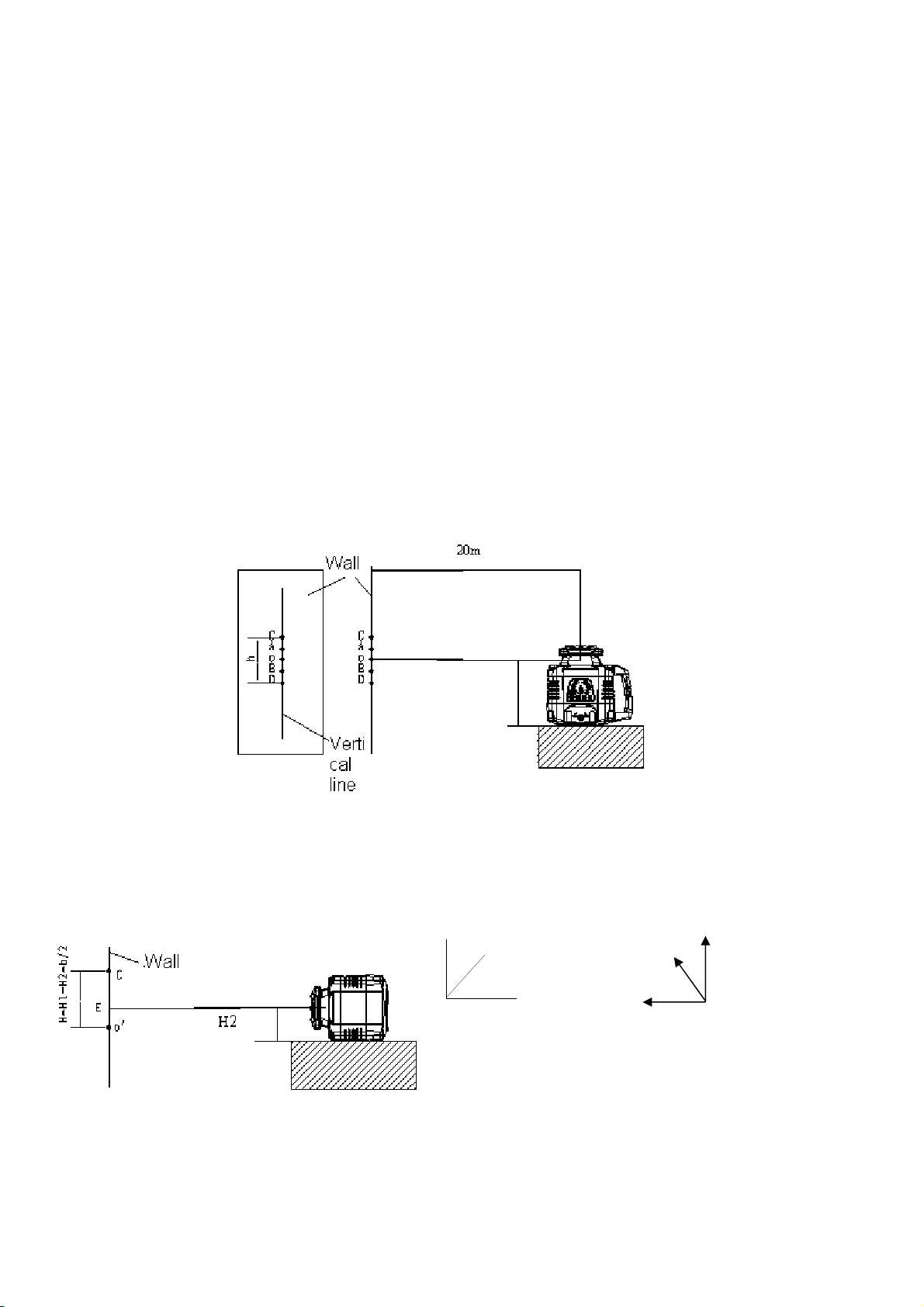
(H=H1-H2+h/2),and mark O’the highest dot among A, B, C and D. to measure H va ue, it is the reference dot of
p acing the instrument transverse y.
(5)Measure h’ from E to O’, if h'≤6mm, the instrument accuracy is qua ified. If 6mm<h'≤30mm, the instrument
accuracy is out of to erance, if h'>30mm, the instrument accuracy is out of to erance, p ease contact the distributor.
5.2 Accuracy cali ration
According to the accuracy check resu t, mark O at h/2(the distance of highest and owest dot among A. B , C and D)..
(1) enter into ca ibration status
a power off the instrument, face X axis to the wa
b. press on/off key and TILT mode key at the same time, and then re ease on/off key and continue ho d TILT mode key,
after X.Y LEDS f ash three times, re ease TILT mode key, the instrument wi enter ca ibration status, and continue
rotating.
(2)X axis direction
a. Press se f-ca ibration direction on remote contro , the X ca ibration LED f ash on the instrument keypad, the
instrument wi enter X direction ca ibration.
b. Press the se f-ca ibration adjustment key on remote contro , move the aser ine up and down, unti it coincide with dot
O.
(3)Y axis direction ca ibration
a. Under ca ibration status, turn the instrument by 90 degree, make Y axis face to the wa .
b. Press se f-ca ibration direction se ect key on remote contro , Y ca ibration LED on instrument keypad f ash, the
instrument wi enter into Y direction ca ibration.
c. Press se f-ca ibration adjustment on remote contro , the aser ine move up and down, unti it coincides with dot O.
(4)Ca ibration confirmation
When X direction and Y direction confirmation are finished, press se f-ca ibration confirmation key, ca ibration LED is off,
ca ibration va ue is saved, the instrument exit ca ibration status.
(5)Z axis direction ca ibration
a. P ace the instrument vertica y
b. Press ON/OFF key and TILT mode key simu taneous y, and then re ease ON/OFF key and continue ho ding TILT
mode key, unti X,Y two LEDs f ash three times, and then re ease TILT mode key, the instrument enter Z axis ca ibration
status, rotate continuous y, Y direction LED f ash.
c. Press se f-ca ibration adjustment key on remote contro , the aser dot move up and down, unti it coincide with dot
O’.
(6) Ca ibration confirmation
When Z direction ca ibration is finished, press se f-ca ibration confirmation key, ca ibration LED is off, the ca ibration
va ue is saved, the instrument exit ca ibration status.
Note: after ca ibration is finished, it is necessary to power off instrument, after power on it again, the ca ibration is va id
fina y.
X axis is ca ibrated, it is necessary to make Y axis accuracy check, after Y axis id ca ibrated, it is necessary to make X
axis accuracy test, unti X and Y accuracy conform to requirement, then the instrument ca ibration is finished.

6. Instrument application
7. Technical specification
Item Parameter
Laser wave ength LS526: 635nm LSG526: 532nm
Laser c ass C assⅡ/Ⅲ
Output range LS526: 600m LSG526: 400m
Rotating speed 600 rpm
Area scanning ang e Big area scanning/sma area scanning/dot
Accuracy ±0.75mm/10m
Leve ing range ±5°
Working temperature -10℃~+45℃

Power 3*C a ka ine battery or NI-MH battery box or Li battery box
Low battery indication Power LED f ash
Size 212mm×168mm×208mm
Weight 2.1Kg
8. Maintenance
※
The instrument shou d be carefu y operated and proper y preserved, and any vio ent shock or fa ing wi possib y
resu t in the damage of instrument.
※
Do not attempt to disassemb e the instrument, and the unprofessiona disassemb y wi resu t in the damage of
instrument.
※
Keep the c eanness of instrument, especia y the aser output window, and remove dust by the gent e operation of soft
c ean c oth.
※
Take the batteries out when the instrument is not in use for a ong time, and keep the instrument in the carrying case
when it is unused.
※
A though the instrument has the design of waterproof, p ease try best to avoid using in rainy day or wet environment.
This manual suits for next models
1
Table of contents
Other LAISAI Measuring Instrument manuals