LAISAI LS609 User manual

Dear User:
Thank you very much for purchasing LAISAI LS609 line laser, please rea this instruction manual before operating
it.
Content
1. Features an functions
2. User safety
3. Instrument nomenclature.
4. Operation gui e
5. Self-check an calibration
6. Demonstration
7. Technical specification
8. Maintenance
1. Feature and functions
LS609 line laser coul separately or simultaneously project self-leveling visible horizontal laser line an vertical line. It
provi e the accurate horizontal, vertical references for in oor layout an calibration. This kin of pro uct is feature by
easy manipulation an wi e applications.
Features:
※ Able to project two laser lines
※ Able to form one cross laser intersection line
※ Self-leveling, with laser flashing in ication if beyon range
※ 1/4” screw threa on the bottom of the instrument
※ Various accessories can exten the purpose of the instrument
Note: This manual coul also apply for high output power laser.
2. User safety
※
Laser output sign is locate at the output aperture.
※
Do not stare into laser beam irectly.
※
Do not isassemble the instrument or attempt to perform any internal servicing. Repairs an servicing coul be
performe only by authorize service centers.
※
The instrument complies with the safety classification stan ar s of laser ra iation.
3. Nomenclature
3.1 Nomenclature of the unit
Operation keypa
Laser output win ow
Self-calibration aperture

3.2 Nomenclature of the bracket
4. Operation guide
4.1 attery mount
Open the battery box cover, put 3*AA alkaline batteries into battery box accor ing to polarity irection, then close the
battery cover.
Battery cover
1/4″ screw threa hole
1/4 ″ screw
threa
Belt slot
5/8″screw threa
Strong magnet
Instrument han wheel
Hanging hole
Tightening knob

4.2. Placement of instrument
a) The instrument can be place on the horizontal platform irectly
b) Able to connect with bracket through 1/4” screw threa on the bottom of the instrument,
Set up on the tripo
Attach on the steel plate
Hang on the wall

Bin on the column
4.3 Operation keypad
Power indication LED
ON(green): power on
OFF power off
ON(re ): low voltage
4.4 Laser output control button
Press for the first time, the vertical line is on.
Press button for the secon time, the vertical line is off, the horizontal line is on.
Horizontal line, vertical line
control button
Power in ication LED

Press button for the thir time, both the horizontal line an vertical line are on at the same time.
Press button for the forth time, both the horizontal line an vertical line are off, there is no laser output.
5. Self-check and calibration
5.1 Horizontal line accuracy self-check (transversely)
a) Fin a smooth wall, set up the instrument on the tripo which is 5 meters away from the wall.
b) Face the instrument on the wall, unlock it an power on all laser lines, there will be a cross laser
line on the wall, set the center of cross line as A ot.
c) Mark A ot an M ot on the horizontal line separately (the istance between both ots is about 2.5m).
) Rotate the instrument, make B ot 5m away A ot.
e) Measure the istance e from M ot to the laser line
f) If e>1.5mm, the instrument accuracy is out of tolerance, it nee s repair.
5.2. Horizontal accuracy self-check (longitudinal)
a) Set up two survey-staffs that are 5 meters away from each other (or two parallel walls that are more than 5m away
from each other).
b) Set the instrument on the elevating or tripo , an
t
hen place the instrument at the center between the two survey-staff,

an level the tripo
c) Power on all laser lines, Make the cross ot
project on the staff A, recor a1 ot value.
) Rotate the instrument by 180°, make the cross ot project on staff B, recor b1 ot value.
e) Move the tripo , make the istance between the instrument an staff A as 0.6m, make the cross ot project on staff A,
recor a2 ot value.
f) Rotate the instrument by 180°, make the cross ot project on staff B, recor b2 ot value.

g) Calculate|(a1-a2)- (b1-b2) |= e ;
f) If e>1.5mm, the instrument accuracy is out of tolerance, an it nee s repair.
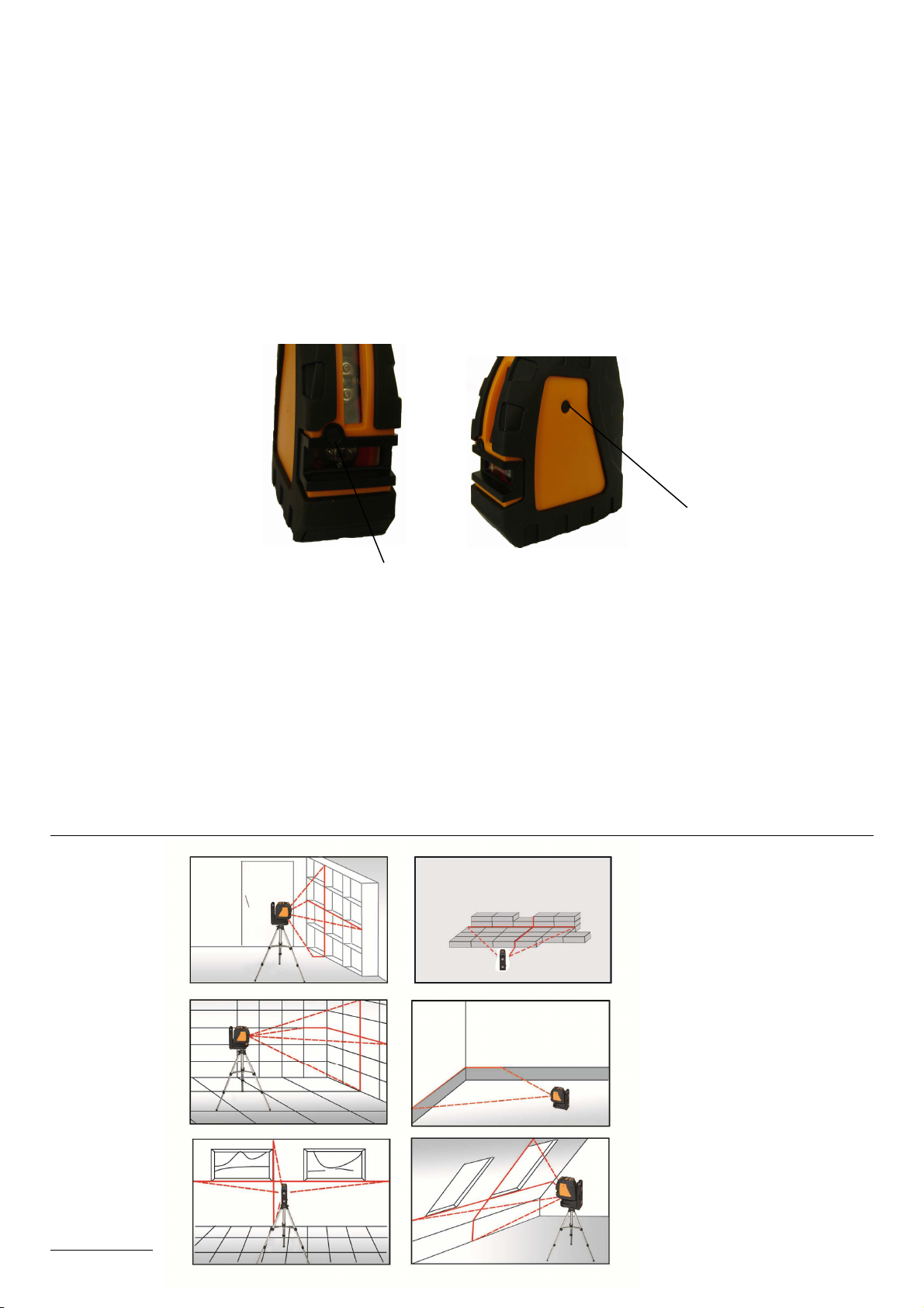
5.3. Self-calibration adjustment
See as following figure, there are two self-calibration apertures on the instrument, the self-calibration aperture A is
correspon ing with the a justment of fore an aft irection (the checke error in item 2 accuracy self calibration), the
self-calibration aperture B is correspon ing with the a justment of left-right irection (the checke error in item 1
accuracy self calibration).
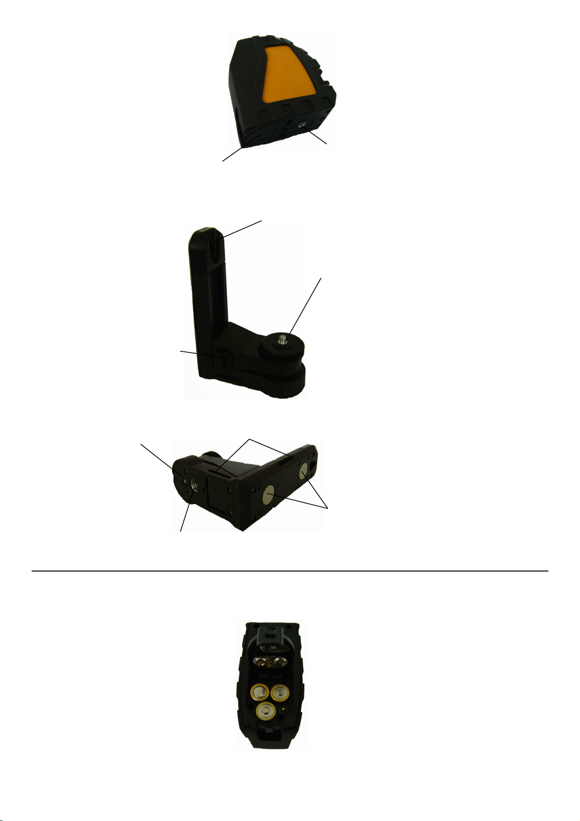
1) When a justing, use the
subtense 3mm hexagon spanner.
2) The a justment of both irections will influence each other. When making fine a justment in the left-right irection,
there may be changes in fore an aft irection. Also, when making fine a justment in fore an aft irection, there may be
changes in left-right irection. Accor ingly, please repeat the a justment of both irections when making fine
a justment.
3) The a justing screw of self-calibration shoul not excee 4 circles (clockwise or anti-clockwise irection).
4) If it can not calibrate the instrument accuracy through the self-calibration aperture a justment, please contact the
ealer for servicing.
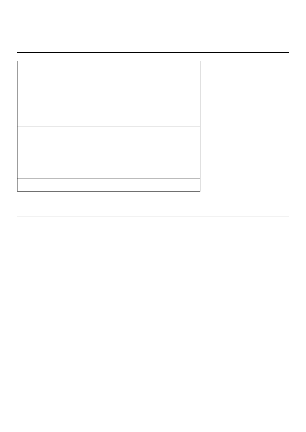
6. Demonstration
Self-calibration aperture A
Self-calibration aperture B

7. Technical specification
Item Parameter
Laser wavelength 635nm
Laser class ClassⅡ/Class III
Accuracy ±1.5mm/5m
Leveling range ±3°
Temperature range
-10℃~+45℃
Power 3*AA battery
Low voltage in ication Power in ication LED is re
Size 104×49×104mm
Weight 0.3Kg
8. Maintenance
Avoi being wet with water an rain.
The instrument shoul be carefully operate an properly preserve , an any violent shock or falling will possibly
result in the amage of instrument.
Do not attempt to isassemble the instrument, an the unprofessional isassembly will result in the amage of
instrument.
Keep the cleanness of instrument, especially the laser output win ow, an remove ust by the gentle operation of
soft clean cloth.
Take the batteries out when the instrument is not in use for a long time, an keep the instrument in the carrying
case when it is unuse .
Table of contents
Other LAISAI Measuring Instrument manuals
Popular Measuring Instrument manuals by other brands

Lake Shore
Lake Shore 211 user manual

In-situ
In-situ Aqua TROLL 700 quick start guide

MH Corbin
MH Corbin NC350 Operation manual addendum

Kyoritsu Electrical Instruments Works, Ltd.
Kyoritsu Electrical Instruments Works, Ltd. 6300 instruction manual

Power Fist
Power Fist 8714941 user manual

Micro Direct
Micro Direct SpiroUSB operating manual