6
THEORIE UND PRAXIS
ZUR VERSTÄRKERSTUFE
Die Verstärkung im MIC-AMP F355 erfolgt
durch einen so genannten Instrumenten-Ver-
stärker. Es ist ein für diese Zwecke optimiertes
IC, dass sich durch seine Rauscharmut bei
hohen Verstärkungen und seine hohe Breit-
bandverstärkung auszeichnet.
Bei einer gewählten Verstärkung von +60 dB
(1000-fach) ergibt sich ein Rauschen, dass
lediglich 1-2 dB über dem theoretisch maximal
erzielbaren Wert liegt.
Die Breitbandverstärkung (GBW = Gain
Bandwidth Product) und die Slew-Rate sind
ursächlich für den Klang eines Verstärkers
verantwortlich. Je höher sie ausfallen, desto
transparenter ist der Klang.
Die Slew-Rate des verwendeten Verstärkers ist
10 V/us, das GBW errechnet sich aus dem
erzielten Frequenzgang bei einer bestimmten
Verstärkung.
Der MIC-AMP F355 hat bei einer Verstärkung
von +60 dB einen internen linearen Frequenz-
gang von weit über 200 kHz. Daraus ergibt sich
ein theoretisches GBW von 200 MHz (200.000
Hz * 1000).
Optional kann der MIC-AMP F355 mit einer
klassischen Class-A Eingangsstufe ausgerüstet
werden.
Gegenüber der Version mit Instrumenten-Ver-
stärker ergeben sich kleine Nachteile im Bezug
auf den Klirrfaktor bei hohen Eingangssignalen.
Im für einen Mikrofon Vorverstärker relevanten
Bereich von +10 ... +50 dB Verstärkung zeich-
net sich die Class-A Version durch einen
geringeren Klirrfaktor aus, bei höheren Ein-
gangspegeln auch durch ein wesentlich gering-
eres Rauschen.
... wie es klingt ???
Nun, wir bei LAKE-PEOPLE geben uns schon
immer jede erdenkliche Mühe, "Klang" zu ver-
meiden.
Der Autor dieses Manuals ist der Meinung, das
sich die Standard Version sehr gut für alle
(Standard-) Anwendungen eignet, die Class-A
Version hingegen ist prädestiniert für "Speziel-
les" Recording !!
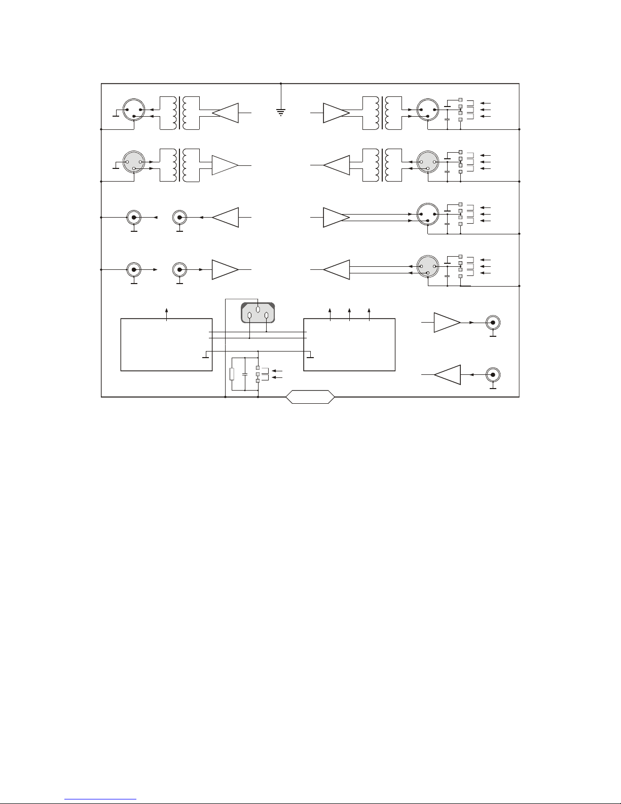
DER SIGNALWEG UND
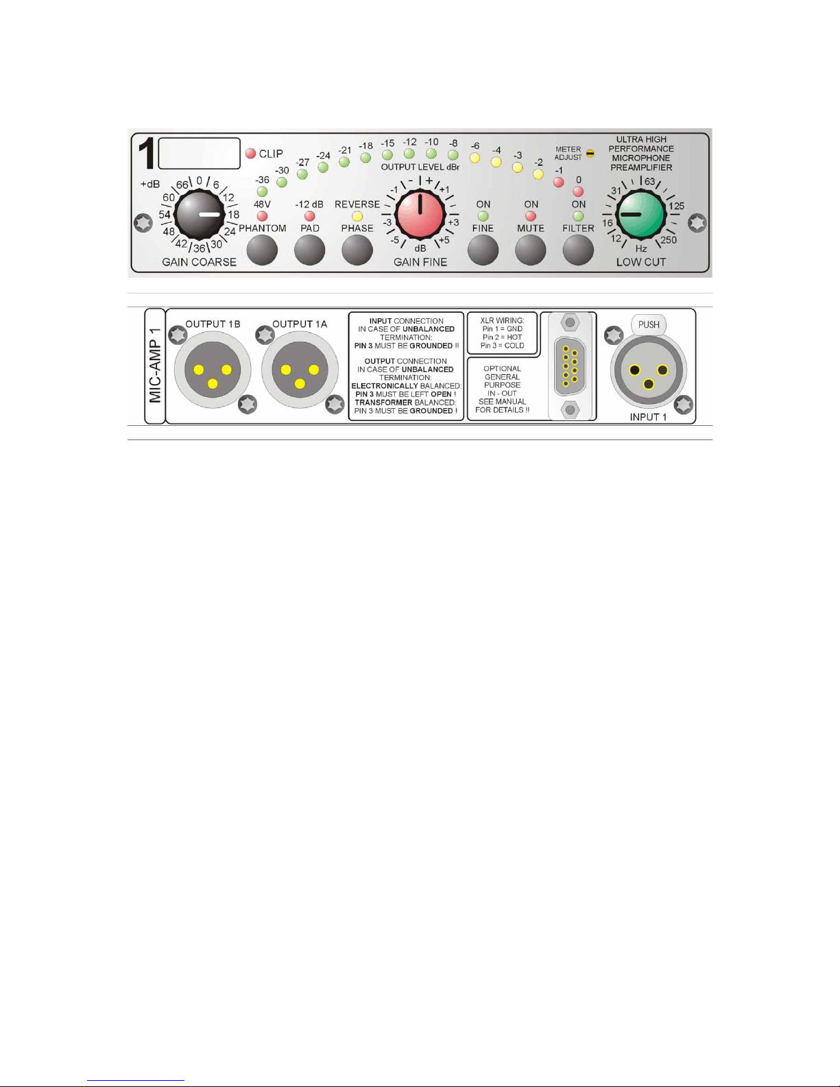
DIE BEDIENELEMENTE
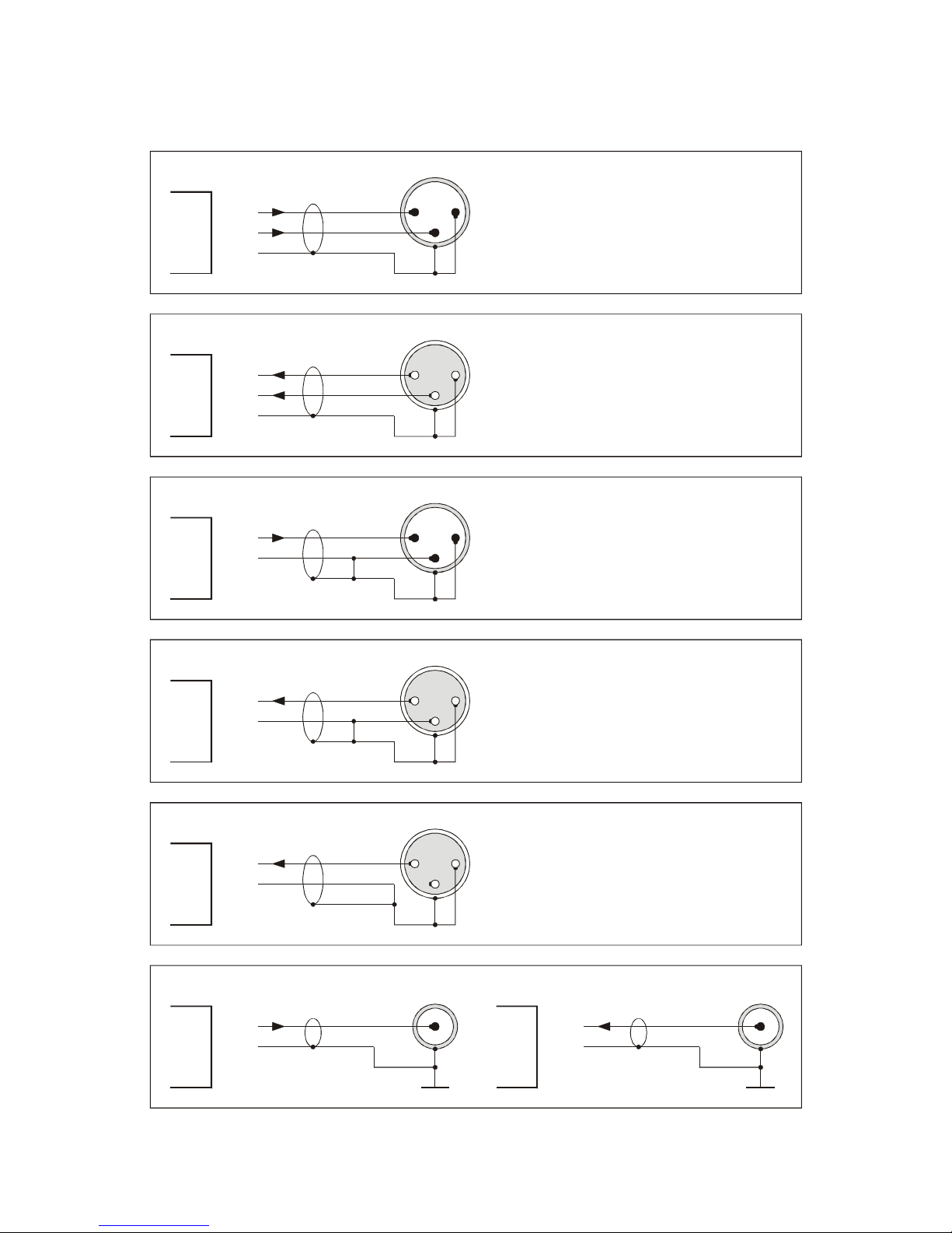
DER EINGANG
Der elektronisch symmetrische Eingang befin-
det sich auf der Rückseite des Gehäuses und
ist mit einer XLR Buchse ausgestattet. Er ist mit
"Input 1" bzw. "Input 2" bezeichnet. Der Ein-
gang akzeptiert symmetrische und unsym-
metrische Audiosignale. Die Belegung ist den
internationalen Normen entsprechend
- 1 = Masse
- 2 = (+) Phase
- 3 = (-) Phase
Bei unsymmetrischem Abschluss des Eingangs
sollte Pin 3 auf Masse gelegt werden.
DIE PHANTOMSPEISUNG
Hochwertige Kondensatormikrofone benötigen
im allgemeinen eine Polarisations- oder
Betriebsspannung, die so genannte Phantom-
spannung.
Der MIC-AMP F355 stellt diese Spannung über
den auf der Front befindlichen "PHANTOM"-
Taster zur Verfügung. Die aktivierte Funktion
wird durch eine rote LED angezeigt.
Sie beträgt ca. 48 Volt und wird gleichphasig
über 6.8 kOhm Widerstände auf die Pins 2 und
3 der jeweiligen Eingangsbuchse gelegt.
Bei üblichen Mikrofon Vorverstärkern führt das
Ein- und Ausschalten der Phantomspannung
konstruktionsbedingt zu niederfrequenten
Spannungsänderungen am Ausgang, die nach-
folgendes Equipment beschädigen können.
Deshalb kann im MIC-AMP F355 ein AUTO-
Mute-Vorgang von ca. 4 Sekunden beim Ein-
und Ausschalten der Phantomspeisung pro-
grammiert werden.
HINWEIS: Nach dem Einschalten der
Phantomspannung stehen 48 Volt
an den Pins 2 und 3 der jeweiligen
Eingangsbuchse.
Eventuell angeschlossenes Line-
Level-Equipment - wie z.B. Synthe-
sizer - kann hierdurch beschädigt
werden.