Lake People DAC RS 06 User manual

1
DIGITAL-ANALOG KONVERTER
DAC RS 06
USER´s MANUAL

2
Content
Theme Page
About Lake People 3
Safety Instructions 5
The Earth / Grounding Concept 7
Connection / Connectors 9
General 10
Operation 12
About Resampling 14
The Menu 16
The Analog Output Level 18
How It Al Works 20
Dismantling 22
Jumper Setting 23
Technical Data 24
Conformity Statement 25
Warranty 26

3
Cordial thanks for your decision in favour of a
Lake People product !
Lake People electronic GmbH develops, manufactures and distributes
products in the professional range, for broadcast, television, airports,
exhibition halls, festival venues, theatres, large-scale installations,
private studios and more. In the private sector as well, Lake People
products become increasingly popular due to their outstanding quality.
Who develops Lake People equipment ?
The devices are exclusively developed in Germany by the engineers of
Lake People electronic GmbH. In doing so, the team of developers can
draw on thirty years of experience and countless products for the pro-
audio domain.
Among others, the first German-made 20-bit A/D and D/A converters
were developed by Lake People in the early nineties of the past century.
Who manufactures Lake People equipment ?
The devices are exclusively manufactured in Germany by Lake People
electronic GmbH or contractors in the company's vicinity.
Lake People puts high emphasis on domestic manufacturing. As well, all
component suppliers are chosen in order achieve the main part of
added value inland.
How do Lake People devices get to the customer ?
Lake People devices can be obtained from respective specialist
suppliers. If there is none such accessible regionally, the customer is
supported by transregional distribution partners (google may help...)
and, of course, by Lake People on-line shop.

4
…and if it doesn't work like it should ?
Lake People devices are covered by a 24-month warranty. In case of
any malfunction during this period, they can be shipped to the
manufacturer directly. Of course, the client will benefit from Lake
People's full technical support even when warranty has expired. Any
technical questions or need for advice is welcome.
LAKE PEOPLE electronic GmbH
Turmstrasse 7a
D-78467 Konstanz
Fon +49 (0) 7531 73678
Fax +49 (0) 7531 74998
Mail: info@lake-people.de
www.violectric.de www.violectric.com
www.lake-people.de www.lake-people.com

5
General Safety Instructions
WARNING
For your protection, please read the following:
Water, Liquids, Moisture:
This appliance should not be used near water or other sources of liquids.
Care should be taken so that objects do not fall and liquids are not spilled into
the enclosure through openings.
Power Sources:
The appliance should be connected to a power supply only of the type described
in the operating instructions or as marked on the appliance.
Grounding:
Care should be taken that this appliance is operated with proper grounding only.
Power Cord:
Power supply cords should be routed so that they are not likely to be walked on
or pinched by items placed upon or against them, paying particular attention to
cords at plugs, convenience receptacles, and the point where they exit from the
appliance.
This unit is equipped with a 3-pole mains cable with German 3-pin mains plug.
In some countries this unit must be operated with a mains adaptor, supplied by
the owner.
Please refer to the table below to connect a mains plug:
OVERV
IEW: POWER CORD FUNCTION AND COLORS
CONDUCTOR
COLOR
Alternativ
L
LIVE
BROWN
BLACK
N
NEUTRAL
BLUE
WHITE
E
PROTECTIVE EARTH
GREEN+YELLOW
GREEN
U.K. Mains Plug Warning:
A moulded mains plug that has been cut off from the cord is unsafe. Discard the mains
plug at a suitable disposal facility.
NEVER UNDER ANY CIRCUMSTANCES SHOULD YOU INSERT A DAMAGED OR
CUT MAINS PLUG INTO A 13 AMP POWER SOCKET. Do not use the mains plug
without the fuse cover in place. Replacement fuse covers can be obtained from your local
retailer. Replacement fuses are 13 amps and MUST be ASTA approved to BS 1362.

6
Mains Fuse:
The mains fuse of this appliance is soldered in place and accessible from the
inside only!!
A blown fuse may indicate an internal problem and should be replaced during
qualified servicing or repair work !!
Switchable Power Supply:
Connect this unit to the power source indicated on the equipment rear panel
only to ensure safe operation !!
This unit is provided with a switch-mode AC power supply and will work properly
with all worldwide AC voltages from 90 –260 V AC and 50 –60 Hz.
Service / Repair:
To reduce the risk of fire or electric shock, the user should not attempt to service the
appliance beyond the measures described in the operating manual. All other
servicing or repair should be referred to qualified personnel !!
Electromagnetic Compatibility
This unit conforms to the Product Specifications noted as Declaration of
Conformity at the end of this manual. Operation is subject to the following
conditions:
- this device may not cause harmful interferences
- this device must accept any interference received,
including interference that may cause undesired operation
- this device must not be operated within significant electromagnetic field
VOR DEM ÖFFNEN NETZSTECKER
ZIEHEN!! PULL MAINS BEFORE
OPENING!! AVANT D´OUVRIER
RETIREZ LA FICHE MALE!!

7
Das Erde / Masse Konzept
General GROUND-LIFT Jumper - accessible from the inside.
Mind the SECURITY INSTRUCTIONS !!
Ex-works this jumper is set to the LIFT position.
The internal ground potential is “lifted”by means of this jumper.
As a result, the interconnection for DC voltages and lower frequencies
(< 150 Hz) will be cut. Higher frequencies will be bled off to earth
potential through the RC filter. The LIFT position is helpful in case of
hum or jitter caused by different ground/earth potentials.
Of course full electrical protection is granted as the case is always
connected to ground/earth potential !

8
Unfortunately there is no general recommendation how to solve hum
and jitter problems - or even minimize them. The best way to succeed is
to check different options !! In case of balanced cables, it should always
been verified if the shield of the cable is connected to the shell of the
XLR connector. The shell is ALWAYS connected to earth potential when
the connector is inserted !!
Concerning ANALOG inputs and outputs, the relationship between
ground and earth may be modified. Electrical safety is always ensured,
since the earth conductor is permanently connected to the enclosure !!
Please note that with jumpers in LIFT or GROUND position
EMC emission might occur,
for which the user is responsible only !

9
Connection / Connectors

10
GENERAL INFORMATION
LAKE PEOPLE DAC RS 06 is a top-range D/A converter, distinguished
by its resampling unit, its 32-bit double mono converters and very
particular analog output stages. By means of their specially designed,
variable low-noise and low-distortion circuitry, the DAC RS 06 fulfils
even highest demands.
Features:
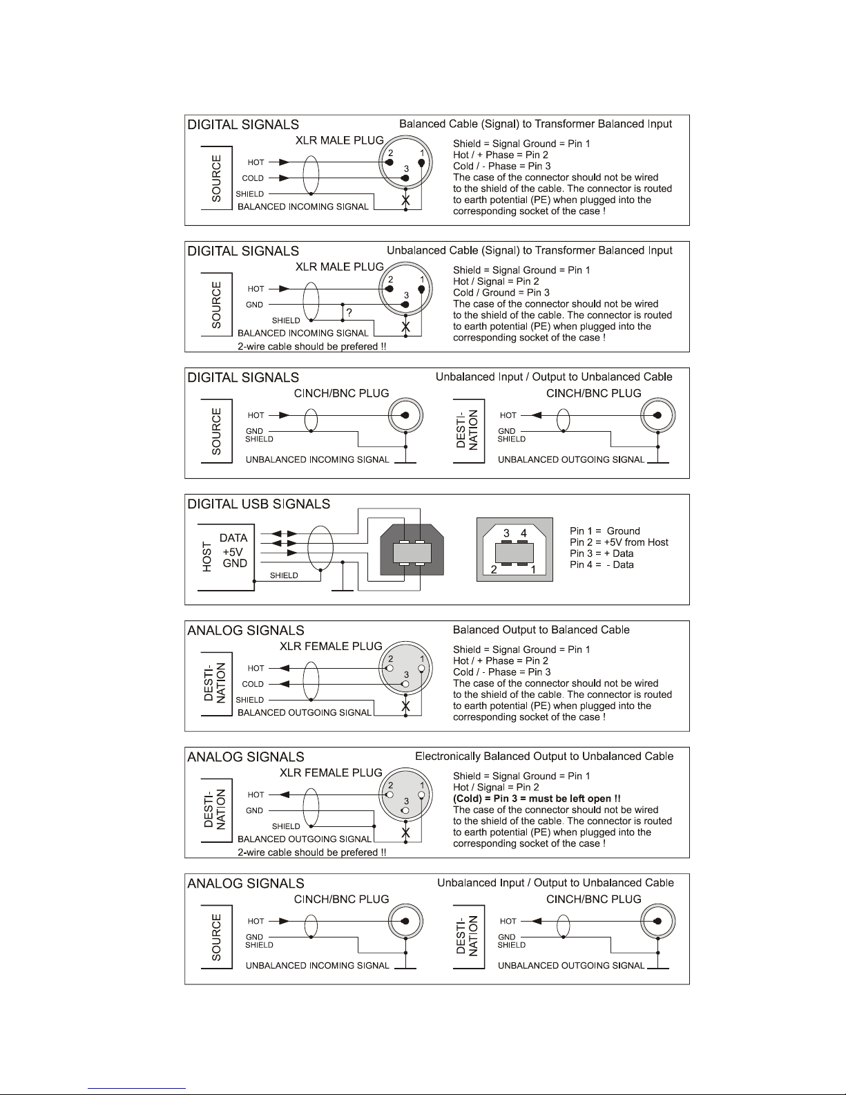
- four switchable digital inputs:
- transformer balanced via XLR (AES 3), 24 bit / 192 kHz
- coaxial via RCA (S/P-DIF, AES-3id), 24 bit / 192 kHz
- optical via TOS-Link, 24 bit / 192 kHz
- USB 24/96 input Style B, transformer-coupled,
- USB 24/192 as an option
- coaxial digital output
- LED signaling for active input, lock, error/mute and resampling mode
- resampling / upsampling set to 96 kHz
- 32 bit double-mono converters ( 2 converters per channel )
- Delta-Sigma D/A converter with 120 dB dynamic range / -112 dB THD
- output level adjustable on the front panel
- sophisticated analog output stages, max. dyn. range / min. distortion
- 4 output levels adjustable via software
+3/+9/+15/+21 dBu for the balanced output respectively
-3/+3/+9/+15 dBu for the unbalanced output
- high-quality op-amps along the signal path
- high-quality MKP capacitors along the signal path
- 0,1 / 1 % metal film resistors throughout the unit
- balanced signals from the D/A converters to the outputs
- analog outputs electronically balanced via XLR, unbalanced via RCA
- elaborate supply voltage, low ERS caps for filtering and stabilization
- black aluminum case

11
THE CASE
The case as well as the front/rear panels are made of solid aluminum.
This choice of material ensures high mechanical stability and resistance.
EARTH AND GROUND
The case of DAC RS 06 is grounded. Internal reference ground is
bridged to protective earth by means of a jumper. The jumper is set to
the 'LIFT' position (see also: page 7 "Earth/Ground concept", page 23
"Technical Appendix").
POWER SUPPLY
Mains power is provided via a three-pin IEC/CEE socket and mating
"cold-appliance" mains cord with Schuko-type plug. Depending on the
location of purchase other mains cords like GB-style, US-style or China-
style may be supplied.
This unit offers a switch-mode supply to enable trouble free worldwide
operation with mains voltages ranging from 90 –260 V and 50 –60 Hz.
The internal supply generates a stabilized and filtered voltage of 5 V DC
which is used for many digital building blocks and from which other
voltages are derived:
-/- 15 Volt, stabilized and filtered for the analogue circuitry.
+3,3 Volt, stabilized and filtered for other digital circuitry.
MAINS FUSE
The 1 A time-lag fuse is soldered in place on the circuit board. In case, it
must be replaced with a fuse of the same type only.
CAUTION !!
MIND THE SAFETY INSTRUCTIONS:
A blown fuse indicates an internal fault and
should be replaced during qualified repair or
servicing only !!

12
THE POWER SWITCH
The unit is activated by means of the power switch. Power-on status is
indicated by the green LED below.
THE DIGITAL INPUTS
Four digital inputs are found on the unit's rear panel. They are denoted
according to their electrical properties: balanced, coaxial (unbalanced),
optical and USB.
You won't find terms like AES, S/P-DIF, professional or consumer here,
since it doesn't matter at all which signal type is applied to a dedicated
input.
The electrical inputs (Bal and Coax) accept PCM-encoded digital audio
data with a word length of 16 ... 24 bit and 28 ... 210 kHz sample rate.
So does the optical input.
- The balanced input is equipped with an XLR socket according to
AES 3-1992, transformer-balanced, at 110 ohms input impedance
and 200mV sensitivity at Tnom/2.
- The coaxial input is fitted with a RCA socket according to IEC 958
and AES-3-id resp., unbalanced at 75 ohms input impedance and
200 mV sensitivity at Tnom/2
- The optical input provides a TOS-Link connector according to EIAJ
RC-5720.
- The USB terminal is specified as audio interface according to USB
1.1 / 2.0 standard. The 24/96 or 24/192 USB circuitry uses the Tenor
chip set. It accepts a choice of the usual sample rates which may be

13
dependend on your specific computer and/or software.
The 24/96 USB input is USB 1.1 based and normally runs without a
specific software. For the 24/192 USB circuitry a special driver is
needed which can be downloaded on our web site
www.violectric.com or www.violectric-usa.com
In order to avoid any interference caused from the host, the USB
input is fully insulated, with the signal coupled via transformer.
THE DIGITAL OUTPUT
is located on the rear panel. It is fitted with a RCA socket according to
IEC 958, unbalanced, at 75 ohms output impedance. The level at this
output however complies with AES-3-id (1 Vss).
The data word on this output is the same as on the selected input with
the identical sample rate when the resampling process is not activated.
When the resampling process is activated, the sample rate on this
output is 96 kHz.
THE ANALOG OUTPUTS
are situated on the rear panel, fitted with electronically balanced XLR
terminals, as well as RCA sockets.
The unbalanced outputs are generated from the in-phase signals of the
balanced outputs and so should not be used simultaneously when the
following input stages have impedances lower than 5 kOhm.

14
Polarity of the XLR terminals complies with AES 14-1992:
1 = ground, 2 = (+) in phase, 3 = (-) out of phase.
Source impedance of all analog outputs is significantly lower than
1 (one) Ohm !
NOTE:
When connecting unbalanced lines to the balanced outputs, pin 3 must
not be bridged but left unused (open). In this case the resulting output
level will be 6 dB less.
INPUT SELECTION
By pressing the “INPUT SELECT“button, the inputs BALanced >
COAXial > OPTO > USB can be selected.
If a valid signal is present at the corresponding input, the blue "lock"
LED will come up. Unused inputs or such with an invalid digital signal
present are indicated by the red “MUTE / ERROR“light.
THE RESAMPLING BUTTON
serves to switch on and off the resampling process.
The active resampling is shown by the yellow “ON”LED.
Resampling means that all input jitter is removed and the input signals
are converted into a 96 kHz sample rate. This is the frequency at which
most contemporary converters perform best.

15
RESAMPLING
is a mighty feature for the transformation/restoration of jittered signals
into high-quality signals. As well, the signal quality of 44.1 or 48 kHz
sources can be improved by converting them to a higher rate. This also
complies to the USB input which often suffers from jitter caused by
improper treated computer outputs. With the aid of resampling process
nearly all jitter (and not only specific ones) is removed from the USB
data stream without using “asynchronous USB mode”which is
nonetheless also a feature of the USB input.
This isn't mystery at all, but a feature offered by so called sample-rate
converters - available since the nineties of the past century.
While early sample rate converters could provide conversion ratios of
1:2 to 2:1 at 100dB dynamic range only, ratios of 1:16 to 16:1 at 140 dB
dynamic range are feasible today.
In principle, the digital data stream is asynchronously disassembled by a
DSP specially developed for this purpose and can be recombined at
virtually any sample rate desired.
The quality of this recombination is directly dependent from the SRC´s
clock source. Therefore inside DAC RS 06 a special low jitter oscillator
with typical < 1 pS (Picosecond !) phase jitter is used.
The oscillator is powered by a low noise source made of discrete
components. By means of this process, all potential jitter vanishes
almost completely and - due to the higher sampling rate - the analog
filters after the converter stage can follow a much more straightforward
and "musical" design. Furthermore, all digital input signals will be
completed to 24 bit.

16
THE MENU consists of two points.
To enter the MENU push and hold the right “RESAMPLING”button for
two seconds. The yellow “ON“LED flashes constantly. The green LED
under “BAL”flashes once to show that Menu 1 is entered. Afterwards it
is either on or off.
1st Menu item: Sharp or soft digital filter in the D/A converter
The status may be altered by pushing the left button.
LED off = the digital filter has sharp roll-off (ex works setting)
LED on = the digital filter has soft roll-off.
The digital filter has some influence on the conversion process. When
generally digital audio data with more than 80 kHz sampling sate is
input, the filter may be set to soft roll-off.

17
Depressing shortly the right button again calls the 2nd Menu item.
The yellow “ON“LED keeps flashing constantly.
The green LED under “COAX”flashes once to show that Menu 2 is
entered. Afterwards it is either on or off.
2nd Menu item: the phase correlation of the analog outputs
The status may be altered by pushing the left button.
LED off = no phase shift on the analog outputs (ex works setting)
LED on = 1800phase shift on the analog outputs.
Specially when more than one D/A converter is engaged a different
phase on the outputs may be helpful.
Please note that the phase of all outputs is reversed: the left and right
channel and the balanced and unbalanced output.
Exit the menu
To exit the menu push and hold the right “RESAMPLING”button for
more than two seconds.

18
ABOUT THE ANALOG OUTPUT LEVEL
Unlike in the analog world, digital technology uses a clearly defined
maximum level, described as 0 dBFs, or "zero deciBels Full scale" in
clear text. From this maximum downward, signal levels are expressed
with a negative sign.
The “translation“of the digital level into analog is provided by the D/A
converter and is extremely flexible, whereby several standards have
established.
Professional broadcast facilities in Germany - i.e. radio and TV stations -
understand 0 dBFs as equivalent to +15 dBu analog level.
In other countries this may be handled differently.
Notabene, +15 dBu represent a voltage of 4.5 Veff which may exceed
the capabilities of many audio devices designed for a voltage swing of
1...2 volts. Therefore, the maximum output level of the DAC RS 06 can
be adapted by means of software. While factory-preset to +15dBu, the
maximum balanced output level can as well be set to +21 / +15 / +9 / +3
dBu. The unbalanced outputs have always 6 dB lower level: +15, +9,
+3, -3 dBu (+9 dBu ex works).
While the level adjustments are made inside the D/A converter, these
settings have no influence on the very low output impedance of all
analog outputs.
Also there will be no signal degradation due to the truncation of the
digital signal as the level setting is part of the 32 bit conversion process.
Theoretically the signal can be attenuated by 8 bit or 48 dB without
touching the original 24 bit resolution. When there are only 16 bit signals
present on the digital input (CD quality), the same would be true for 16
bit or 96 dB attenuation.

19
THE SETTING OF THE ANALOG OUTPUT LEVEL
To enter the setting push and hold the left “INPUT SELECT”button for
two seconds. The blue “LOCK”LED flashes constantly. One or more
green LEDs will be lit constantly.
1 LED = output level +3 (-3) dBu for 0 dBFs
2 LEDs = output level +9 (+3) dBu for 0 dBFs
3 LEDs = output level +15 dBu (+9) for 0 dBFs (ex works)
4 LEDs = output level +21 (+15) dBu für 0 dBFs
The above levels are related to the balanced analog outputs.
The unbalanced output levels are denoted in ( ) brackets.
The output level may be altered by pushing the left or right button
shortly. The blue “LOCK”LED remains flashing.
Exiting the level setting
To exit the level setting push the left “INPUT SELECT“button for more
than 2 seconds. The blue “LOCK”LED stops flashing.

20
HOW IT ALL WORKS...
The DAC RS 06 offers high-class technology by means of well thought-
out handling, a variety of inputs, the resampling module, top-notch
converters and, above all, its outstanding and flexible analog output
circuitry.
Taken from one of four possible inputs, the digital signal is forwarded to
the resampling module. If it is activated, its business is to prepare the
incoming signals for processing in the subsequent circuitry. As well, the
sampling rate is generally set to 96 kHz.
The resampling module recognizes the input data as PCM audio and
evaluates the status bits found in the digital signal. Furthermore, the
resampling module expands 16 or 20 bit incoming data to 24 bit data
words and generates auxiliary clock signals needed for further
processing of the digital signal within the unit.
The quality of the resampled signal is directly dependent from its clock
source. Therefore a special low-jitter oscillator is installed which is fed
from its own low noise power supply - build with discrete components.
After the resampling stage, an AES/EBU encoded PCM signal is sent to
the rear digital output, while the data contents and auxiliary clocks are
fed to the digital-to-analog converters.
The D/A converters comprise a digital filter, the output level control, the
stereophonic converters as such, as well as the analog output filters.
Each converter is based on a delta-sigma architecture and provides a
dynamic range of 124 dB. According to the double-mono architecture
two 32 bit D/A converters per channel are used inside DAC RS 06 to
achieve higher linearity and lower noise. An incoming 16, 20 or 24 bit
signal is expanded in a 32 bit signal inside the converters.
The output level setting is part of the 32 bit processing. By this measure
all those should be satisfied who felt uncomfortable concerning bit
truncating whilst attenuating former 16 or 24 bit signals.
The internal frequency of the digital signal (and potential interference
therein) is very high in comparison with the useful analog frequencies.
Therefore, the subsequent analog low-pass filters have to meet less
Table of contents
Other Lake People Media Converter manuals
Popular Media Converter manuals by other brands

Retro Active Arcade
Retro Active Arcade GBS-8200 Ver.3 manual

Visionary Solutions
Visionary Solutions AVN210 user manual

Z3 Technology
Z3 Technology Z3-MVE-02 User instructions

StarTech.com
StarTech.com CONVERGEAV CPNTA2HDMI user guide

SIIG
SIIG RS-232 to Multi-Mode Fiber Optic Quick installation guide

North Star
North Star Fluxio operating manual