Lake People ADC C74 User manual

1
BEDIENUNGSANLEITUNG
USER´s MANUAL Date I/01
ADC C74
24 BIT ANALOG-DIGITAL CONVERTER
Inhalt / Content Seite / Page
Bedienungsanleitung 2
User´s Manual 5
Technical Specifications 8
Pro / Con Bit-Settings 9
Schaltpläne 10
Schematics 10
Lage der Bauelemente 12
Component Layout 12
Konformitätserklärung 13
Confirmity Statement 13

2
HINWEIS:
Für fremde Versorgungsgeräte gilt
- Spannung 8 ... 12 V AC oder DC
- Strom min. 0,4 A
EINSCHALTEN
Vor dem Einschalten sollte überprüft werden,
ob das Steckernetzteil richtig angeschlossen
ist.
Der "POWER"-Schalter befindet sich auf der
Front. Der eingeschaltete Zustand wird über
eine oder mehrere aktive LED´s auf der Front
angezeigt.
Die immer nach dem Einschalten ablaufende
Initialisierungsphase dauert ca. zwei Sekunden
und dient hauptsächlich der Kalibrierung des
A/D Wandlers.
Die digitalen Ausgänge sind dabei stummge-
schaltet.
DIE TAKTERZEUGUNG
Der ADC C74 benötigt diverse Haupt- und Hilf-
stakte zum Betrieb. Die Taktquelle hierfür kann
intern oder extern sein.
Sie wird über den "SYNC-SOURCE"-Schalter
auf der Front ausgewählt.
INTern
In Stellung "INTern" des "SYNC-SOURCE"-
Schalters leuchtet die zugehörige "INT"-LED.
Mit dem daneben liegenden "S-RATE"-Schalter
kann nun die gewünschte Sample-Rate 44.1
kHz oder 48 kHz bestimmt werden.
Die zugehörige gelbe LED "48 kHz" oder "44.1
kHz" leuchtet.
WCLK
In Stellung "WCLK" des "SYNC-SOURCE"-
Schalters wird der Wordclock Eingang auf der
Rückseite des ADC C74 aktiviert.
Der koaxiale Wordclock-Eingang ist als BNC
Buchse ausgeführt.
Die Eingangsimpedanz ist auf 75 Ohm einges-
tellt. Der gültige Taktbereich ist 28 ... 56 kHz.
ALLGEMEINES
Der LAKE PEOPLE ADC C74 ist ein kleiner,
portabeler 24 Bit Analog-Digital Wandler
höchster Qualität. Er wird in mehreren Aus-
führungen geliefert, die sich durch ihre erziel-
bare Dynamik unterscheiden.
Er wandelt ein stereophones analoges Ein-
gangssignal in ein lineares 24 Bit breites digita-
les Ausgangssignal mit einer Dynamik von 105
oder optional 115 dB.
Die analogen Eingänge sind elektronisch sym-
metrisch mit XLR Buchsen ausgeführt. Die Ein-
gangsempfindlichkeit wird mit zwei Potis auf der
Front eingestellt.
Zwei Clip-LEDs warnen vor Übersteuerungen.
Die interne Sample-Rate ist auf 44.1, 48 kHz
einstellbar. Weiter ist eine Synchronisation ex-
tern über WCLK möglich.
Die digitalen Ausgänge sind symmetrisch (AES)
auf XLR und unsymmetrisch (S/P-DIF) auf
Cinch ausgeführt.
Das digitale Ausgangsformat kann auf der Front
auf Professional- oder Consumer-Mode einges-
tellt werden.
DAS GEHÄUSE
Das Gehäuse besteht aus 1 mm starkem Stahl-
blech, die Front- und Rückseite aus 2mm star-
kem Stahlblech.
Dadurch wird eine hohe mechanische Stabilität
und Widerstandsfähigkeit gegen rauhe Be-
triebsbedingungen erreicht.
Die interne Signalmasse ist mit dem Gehäuse
verbunden.
DIE STROMVERSORGUNG
Die Stromversorgung erfolgt über eine einge-
baute 3,5 mm Klinkenbuchse auf der Rückseite
des Gehäuses durch ein mitgeliefertes Stecker-
netzteil. Durch eine integrierte Diode sind Schä-
den durch Verpolungen ausgeschlossen!
Die Belegung ist: Tip = U+ , Sleeve = Masse
Das Netzteil liefert 12 V DC und kann bis 0,6 A
belastet werden.

3
Die roten LEDs leuchten bei einem Pegel von
ca. -1 dB unterhalb der Vollaussteuerung und
sollen auf drohendes Übersteuern hinweisen.
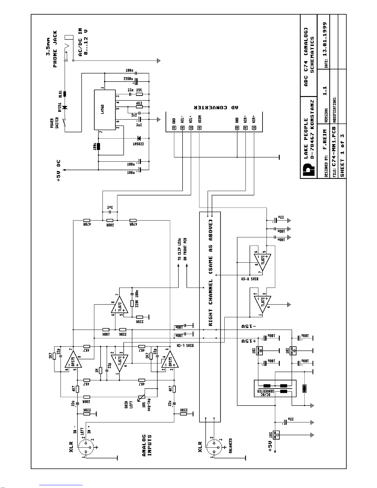
DER A/D WANDLER
Der Wandler im A/D Teil ist in der Standard-
ausführung ein 48 kHz - 24-Bit Wandler mit 105
dB Dynamik.
Gegen Aufpreis ist z.Z. ein 48 kHz - 24 Bit
Wandler mit 115 dB Dynamik erhältlich.
Der ADC C74 ist aufgrund seiner recht uni-
versellen Auslegung für viel heutige und zu-
künftige Wandler geeignet.
Da der A/D-Wandler Chipmarkt momentan sehr
lebendig ist, sind Verbesserungen der Wandler
möglich und können meist auch sehr leicht ein-
gebaut werden.
Die Fa. LAKE PEOPLE wird in ihrer Web-Site
(www.lake-people.de) auf mögliche Updates
hinweisen!
DIE DIGITALEN AUSGÄNGE
Der A/D Wandler stellt je einen symmetrischen
und einen koaxialen digitalen Ausgang zur Ver-
fügung.
Das Datenwort (Professional- oder Consumer-
format) ist an allen Ausgängen gleich, unabhän-
gig von der Norm oder Bauweise der Anschlüs-
se.
Die Ausgänge befinden sich auf der Rückseite
des Gehäuses und sind entsprechend bezeich-
net:
- Der symmetrische Ausgang ist als XLR-Ver-
binder ausgeführt und entspricht AES 3-
1992, Ausgangsimpedanz 110 Ohm.
- Der koaxiale Ausgang ist als Cinch Buchse
ausgeführt. Er entspricht IEC 958, unsym-
metrisch, Ausgangsimpedanz 75 Ohm.
DAS DIGITALE AUSGANGSFORMAT
Das digitale Ausgangsformat (Professional-
oder Consumer) ist über den "FORMAT"-
Schalter auf der Front einstellbar.
Näheres dazu siehe "BIT-SETTING", Seite 9.
Sowie ein gültiger Takt erkannt wurde leuchtet
die "WCLK LOCK"-LED. Wenn sich der Takt in
einem Bereich von +/- 200 Hz um die Frequen-
zen 44.1 oder 48 kHz bewegt, leuchtet zusätz-
lich eine der beiden Sample-Rate LED´s.
Durch ein fehlerhaftes Sync-Signal am WCLK-
Eingang erfolgt eine Stummschaltung des A/D
Wandlers und die "WCLK LOCK"-LED erlischt.
DER FORMAT-SCHALTER
Der "FORMAT"-Schalter beeinflusst das digitale
Ausgangswort des ADCs (siehe "BIT SET-
TING" auf Seite 9):
- Der Professional-Mode ist eingestellt, wenn
die gelbe "PRO" LED leuchtet: Das Format
des digitalen Ausgangswortes des A/D
Wandlers wird auf den Professional-Mode
gesetzt.
- Der Consumer-Mode ist eingestellt, wenn die
gelbe "CON" LED leuchtet: Das Format des
digitalen Ausgangswortes wird auf den Con-
sumer-Mode gesetzt.
DIE ANALOGEN EINGÄNGE
Die analogen Eingänge befinden sich auf der
Rückseite und sind als symmetrische XLR
Buchsen ausgeführt.
Die Polarität entspricht AES 14-1992:
1 = Masse, 2 = (+) Phase, 3 = (-) Phase.
Die Eingangsimpedanz beträgt 5 kOhm, die
Eingangsempfindlichkeit für Vollaussteuerung
ist für beide Eingänge getrennt von ca. +2 ...
+21 dBu einstellbar.
DIE EINGANGSREGLER
Mit den für Links und Rechts getrennten
"GAIN"-Reglern kann das Eingangssignal abge-
glichen werden. Der Bereich beträgt ca. +2
...+22 dBu für die Vollaussteuerung.
DIE CLIPANZEIGE
Die "CLIP"-LEDs befinden sich für jeden Kanal
getrennt über den zugehörigen Einstellreglern.

4
DIE FUNKTION
Die analogen Eingangssignale gelangen in eine
Pufferstufe und können hier in ihrem Pegel
durch zwei Potis auf die Empfindlichkeit des
Wandlers abgestimmt werden.
Das analoge Frontend wurde sehr sorgfältig
konstruiert und hat eine Dynamik >126 dB - ge-
nug also für zukünftige Wandlergenerationen.
Das Herz ist natürlich der A/D Wandler. Er prä-
sentiert sich jetzt und zukünftig als Delta-Sigma
Wandler mit 64...128-fachem Oversampling.
Der linke und der rechte Kanal werden ge-
meinsam gesampelt.
Ein Digitalfilter auf dem Wandlerchip sorgt für
eine hohe Dämpfung von nicht erwünschten
Aliasfrequenzen. Die digitale Wandlung des
Eingangssignals ist innerhalb gewisser Gren-
zen unabhängig von seiner Frequenz und Am-
plitude. Das digitale Ausgangswort liegt in se-
rieller Form im Zweierkomplement vor.
Um zu funktionieren, benötigt der A/D Wandler
einige Takte. Sie werden intern aus Quartz-
oszillatoren erzeugt, oder extern über eine PLL
aus einem WCLK- oder AES-Signal gewon-
nen.
Nach dem Verlassen des A/D Wandlers wird
das digitale Signal in einem weiteren Baustein
zu AES/EBU- bzw. S/P-DIF-konformen Signa-
len aufbereitet, um danach in normierter Form
zu den digitalen Ausgängen zu gelangen.
HINWEIS:
Im Consumer-Mode wird das SCMS wie folgt
eingetragen:
- Byte 0, Bit 2=1: copy permitted / copy-right
not asserted.
- Byte 1, Bit 7=0: original / pre-recorded data
WIE FUNKTIONIERT'S
PRÄMBEL
Der ADC C74 bietet in seinen verschiedenen
Versionen Spitzentechnologie.
Durch die gestaffelten Ausführungen ist es dem
Benutzer möglich, eine differenzierte Preis-
Leistungs Optimierung durchzuführen.
Alle Versionen sind mess- und hörbar besser
als Standard 16-Bit Wandler, wie sie üblicher-
weise in DAT Recordern, Hard-Disk Recordern
oder digitalen Mehrspurmaschinen eingesetzt
werden - selbst wenn die digitalen Signale im
Aufnahmemedium auf 16 Bit begrenzt werden!
Wichtiger als die Angabe der verfügbaren Bit-
breite der einzelnen Wandler ist für uns bei LA-
KE PEOPLE die erzielbare Dynamik.
Wir denken, dass diese Angabe aussagekräfti-
ger und ehrlicher ist als die immer nur theoreti-
sche Angabe der erzeugten Bitbreite am Aus-
gang.
Wer es genau wissen möchte, kann nach fol-
gender vereinfachten Formel verfahren:
Auflösung in Bit = Dynamik / 6
Daraus ergibt sich eine tatsächliche Auflösung
von ca. 17,5 Bit für die 105 dB Ausführungen,
und 19,2 Bit für die 115 dB Ausführungen. Der
Rest ist im wahrsten Sinne Rauschen!
Anzumerken wäre noch, dass unsere Werte A-
bewertet (wie bei allen anderen) angegeben
werden. Nach den Messvorschriften "RMS un-
bewertet" oder "CCIR Quasi-Peak 2K" ergäben
sich bis 10 dB schlechtere Daten.

5
HINT:
Other Wall plug adaptors or AC/DC power
supplies may be used with the ADC C74 under
the follwing circumstances:
- Voltage 8 ... 12 V AC or DC
- Current min. 0.5 A
POWER UP
Before operating the "POWER"-switch the wall
plug adaptor should be connected in a correct
way with the ADC C74.
The "POWER"-switch is situated on the front
panel. Power-on is indicated by one or more il-
luminated LED´s on the front panel.
After powering the unit, a two second initalising
sequence is run which serves mainly to calibra-
te the A/D converter chip.
During power-up the digital outputs are muted.
THE SYNC SOURCES
An A/D converter needs some clocks to operate
in a proper way. These clocks may be derived
internally or externally by means of the "SYNC-
SOURCE"-switch.
INTernal
When operating the "SYNC-SOURCE"-switch
to the internal clocks the "INT"-LED is lit.
With the "S-RATE"-switch nearby 44.1 kHz or
48 kHz internal sampling-rate may be selected.
The selected sample frequency is displayed by
two yellow LED´s "48 kHz" and "44.1 kHz" on
top of the "S-RATE"-switch.
WCLK
When operating the "SYNC-SOURCE"-switch
to the "WCLK" position, the external wordclock
input on the back of the unit is activated.
Sync-signals are input via a BNC connector.
The input impedance is set to 75 ohms, the va-
lid clock ranges from 28 ... 56 kHz.
As soon as a clock is recognized as a valid sig-
nal the "WCLK LOCK"-LED is lit.
GENERAL
The LAKE PEOPLE ADC C74 is a small, por-
table analog-to-digital converter of highest qua-
lity in a small case.
The unit converts an analog stereo input into a
24 bit digital output signal with 105 dB dynamic
range.
Optionally the unit is deliverable with an enhan-
ced converter-chip with 115 dB dynamic range.
The analog inputs are electronically balanced
via XLR sockets. The input sensitivity is adjus-
ted by two rotary faders on the front panel.
Two clip LED´s warn in case of signal overload.
The internal sampling-rate can be switched ei-
ther to 44.1 or 48 kHz on the frontpanel. Fur-
thermore an external WCLK-sync input is provi-
ded.
The two digital outputs are matching balanced
(AES/EBU) as well as unbalanced (S/P-DIF)
standard via XLR respectively Cinch sockets.
The digital output format can be set to consu-
mer or professional standard by a frontside
switch.
THE CASE
The case is crafted from 1 mm steel sheet while
front- and backpanels are made from 2 mm
steel.
This construction offers a maximum of me-
chanical stability and withstands even rough en-
vironmental conditions.
The internal signal ground is connected to case
ground.
POWER SUPPLY
The unit is powered by a wall plug adaptor via
the built-in 3.5 mm phone-jack on the rear pan-
el. Because of the integrated rectifier diode no
damages can occur when accidentially the po-
wer supply is reversed!
The connection of the 3.5 mm phone-jack is:
Tip = U+, Sleeve = Gnd

6
THE A/D CONVERTER
The A/D converter of the standard version is a
48 kHz - 24 bit converter with 105 dB dynamic
range.
At extra cost optionally a 48kHz - 24 bit conver-
ter with 115 dB dynamic range is deliverable.
Because of its internal fexibility the ADC C74 is
suitable for many today and future convertes.
As far as the chip market for A/D converters is
very vivid in the moment, enhanced converters
may be built in mostly in an easy way.
LAKE PEOPLE will refer to possible future up-
dates on their web pages (www.lake-peo-
ple.de).
THE DIGITAL OUTPUTS
The ADC C74 is equipped with a balanced and
a coaxial output. The digital output word (pro-
fessional- or consumer format) on each output
is identical, regardless of the physical and elec-
trical standard. The outputs are situated on the
rear panel.
- The balanced output, signed with "BAL", com-
plies with AES 3-1992 standard and is equip-
ped with an XLR type terminal, electronically
balanced at 110 ohms impedance.
- The unbalanced output, signed with "COAX",
is equipped with a cinch socket, meets IEC
958 specifications at 75 ohms impedance.
THE DIGITAL OUTPUT FORMAT
The digital output format is selected with the
"FORMAT“ switch on the front panel and may
be fixed to professional- or consumer standard.
The corresponding LED´s "PRO" or "CON" are
lit. For more information see "BIT-SETTING"
table on page 9.
HINT:
In consumer mode, SCMS information is hand-
led as follows:
- Byte 0, Bit 2 = 1 = copy permitted / copyright
not asserted.
- Byte 1, Bit 7 = 0 = original / pre-recorded
data
When the external frequency is within a range
of +/- 200 Hz around 44.1 kHz or 48 kHz, the
corresponding "S-RATE"-LED´s are lit, too.
A faulty sync-signal on the WCLK input forces a
mute of the A/D converter and the "WCLK
LOCK"-LED is not illuminated.
THE FORMAT SWITCH
The "FORMAT"-switch influences the digital
output word of the ADC C74 (see "BIT SET-
TING" table on page 9.
- Professional mode is selected when the yel-
low "PRO"-LED is lit. The digital output for-
mat of the ADC C74 is set to professional
mode.
- Consumer mode is selected when the yellow
"CON"-LED is lit. The digital output format of
the ADC C74 is set to consumer format
THE ANALOG INPUTS
The analog inputs are situated on the rear pan-
el, equipped with balanced XLR.
The pinout corresponds to AES 14-1992:
1 = Ground, 2 = (+) Phase, 3 = (-) Phase
Input impedance is 5 kOhms, while input sensi-
tivity for digital full scale can be calibrated indi-
vidually for both channels within a range of +2
... +21 dBu approx.
INPUT GAIN ADJUST
By means of two independent rotary gain faders
for left and right channel, input sensitivity can
be set individually. Input level may vary bet-
ween +2 ... +21 dBu for digital full scale.
CLIP LED´s
The red clip LED´s are situated beyond the cor-
responding gain pots and starts flashing at
about -1 dB below digital full scale.

7
THE FUNCTION
The analog input signals are first buffered, then
their level can be adjusted to the converter's in-
put sensitivity by two pots.
The analog front-end had been carefully desig-
ned to achieve a dynamic range of >126 dB,
enough for coming converter generations.
The unit's core is, of course, the A-to-D conver-
ter chip. It is designed for 1-bit delta/sigma con-
version at 64...128 times oversampling. Left
and right channel are processed by one and the
same chip.
The incorporated digital filter provides high atte-
nuation of undesirable alias frequencies. The
conversion process is not influenced by the in-
put signal's level or frequency.
The digital output word is available as a serial
signal in two's complement.
For its task, the A-to-D converter requires a
number of clock signals. These are derived ei-
ther from an internal crystal oscillator or from an
external WCLK signal, pre-processed by the in-
ternal PLL circuitry.
Coming from the converter chip, the digital sig-
nal is translated into a form corresponding to
AES/EBU resp. S/P-DIF standard by a further
integrated circuit. After this, it is available at the
corresponding digital outputs on the rear panel.
HOW IT ALL WORKS....
PREFACE
The ADC C74 in all available versions offers
high-end technology.
By choosing the suitable version to meet his
specific requirements, the customer will take
advantage of an excellent price/performance ra-
tio.
Even the basic model is measurably and au-
dibly better than the middle-of-the-road 16-bit
converters usually found in DAT machines,
harddisk recorders or digital multitrack systems
- even when the digital signals are truncated to
16 bits inside the recording medium.
Much more important than stating the conver-
ters' available bit width is the maximum achie-
vable dynamic range.
We at LAKE PEOPLE consider this parameter
as much more significant and honest than the -
barely theoretic - available output bit width.
For those who want to know in detail:
Bitresolution = dynamic range / 6
This formula leads to an in-fact resolution of
about 17.5 bit for the standard 105 dB version
and 19.2 bit for the enhanced 115 dB version.
There is still to be mentioned, that all our mea-
surements are taken from 20 Hz to 20 kHz with
an A-wtd filter like everbody else does.
Assuming an "RMS unweighted" or "CCIR 2K"
measurement, performance would decrease by
up to 10 dB !

8
TECHNICAL SPECIFICATIONS ADC C74
(All measurements A-weighted, 20 Hz... 20 kHz, 44.1 kHz internal sampling-rate,
referred to digital full scale and +20 dBu analog input level)
Analog Inputs: electronically balanced (XLR), Impedance 5 kOhms
CMRR (@15 kHz): > 60 dB
Input Sensitivity (+/-0.5 dB): +2 dBu ... +22 dBu
Crosstalk (@ 15 kHz): < -100 dB
Clip LED: flashes at -1 dB beyond digital full scale
48 kHz Version 48 (enhanced)
Frequency Range (-0.2 dB): 10 Hz ... 20 kHz 10 Hz ... 20 kHz
THD+N (@ Fs -1 dB): - 93 dB - 105 dB
Dynamic Range: 105 dB (CS 5360) 115 dB (AK 5392)
Stopband Rejection: - 80 dB -110 dB
Internal Oszillators: 44.1 / 48 kHz
WCLK Sync Input: BNC, unbalanced, TTL level (0.5 V min.)
Impedance: 75 ohms
Lock Range: 28... 56 kHz
Slew-Rate: 5 nS
Digital Formats: professional / consumer format selectable
Digital Outputs: - balanced, 110 ohms, XLR, acc. to AES 3-1992
- unbalanced, 75 ohms, Cinch, according to IEC 958
Supply Voltage: 8 ... 12 V AC/DC, max 5 VA via 3.5 mm phone-jack
Dimensions: 130 x 44 x 170 mm (W x H x D)

9
CHANNEL STATUS BIT SETTINGS
PROFESSIONAL MODE CONSUMER MODE
BYTE 0 BYTE 0
BIT 0Pro / Con
I
BIT 0Pro / Con
0
0Consumer use 0Consumer use
IProfessional use IProfessional use
BIT 1Audio/Non Audio
0
BIT 1Audio/Non Audio
0
0Normal Audio 0Normal Audio
INon-Audio INon-Audio
BIT 234 Signal Emphasis
0 0 0
BIT 2Copy / Copyright
I
0 0 0 not indicated 0Copy inhibited
I0 0 None ICopy permitted
I I 050/15 uS BIT 3 4 5 Preemphasis
0 0 0
I I I CCITT J.17 000 None
BIT 5Lock: Source
0
I0 0 50/15 uS
0Locked - default BIT 6 7 Mode
0 0
IUnlocked 0 0 Mode 0
BIT 6 7 Sample-Rate
Calculated
from Sync
0 0 Not indicated
0I48 kHz
I044.1 kHz
I I 32 kHz
BYTE 1 BYTE 1
BIT 0 1 2 3 Channel Mode
0 0 0 0
BIT 0 1 2 3 Category Code
0 0 0 0 ( 0 0 0 )
0 0 0 0 Not indicated 0 0 0 0 General
0 0 0 ITwo-Channel 000 ISolid Sate Memory
0 0 I0Single Channel 0 0 IXBroadcast
0 0 I I Primary - Secondary 0I0XDigital Converters
0I0 0 Stereophonic 0I I 0A/D Converters
0I0IReserved 0I I I Broadcast
0I I 0Reserved I00XLaser Optical
I I I I Vector to Byte 3 I0IXMusical Instruments
BIT 4 5 6 7 User Bits Managem.
0 0 0 0
I I 0XMagnetic Tape or Disk
0 0 0 0 Not defined IIIXReserved
0 0 0 IMain Audio BIT 7Generation Status
I
0 0 I0Single 01st Generation
0 0 I I User defined IOriginal
BYTE 2 BYTE 2
BIT 012 Aux. sample bits
0 0 I
BIT 0 1 2 3 Source Number
0 0 0 0
0 0 0 Not defined, 20 Bit 0 0 0 0 Unspecified
0 0 IMain Audio, 24 Bit I0 0 0 1
0I0Single, 20 Bit 0I0 0 2 ...to
0I I User defined I I I I 15
BIT 345 Word length
I 0 I ( 0 0 )
BIT 4 5 6 7 Channel Number
0 0 0 0
0 0 0 Not indicated 0 0 0 0 Unspecified
0 0 I23 Bit I0 0 0 A
0I022 Bit 0I0 0 B
0I I 21 Bit I I 0 0 C...to
I0 0 20 Bit 0I I I N
I0I24 Bit I I I I O
BYTE 3
0
BYTE 4 BYTE 3
BIT 0 1 Reference Signal
0 0 ( 0 0 0 0 0 0 )
BIT 0 1 2 3 Sample-Rate
Calculated
from Sync
0 0 Not Reference Signal 0 0 0 0 44.1 kHz
0IGrade 1 Ref. Signal 0I0 0 48 kHz
I0Grade 2 Ref. Signal I I 0 0 32 kHz
I I Reserved BIT 4 5 Clock Accuracy
0 0 ( 0 0 )
BIT 234 0 0 Level 2, +/- 1000 ppm
0 0 0 0 ILevel 3, variable
BIT 567 I0Level 1, +/- 50 ppm
0 0 0 I I Reserved
BYTE 5 - 22
0
BYTE 23 CRC BYTE 4 - 23
0

10

11

12

13
KONFORMITÄTSERKLÄRUNG
CONFORMITY STATEMENT
Wir bestätigen hiermit, dass das folgende Gerät
den unten aufgeführten Bestimmungen entspricht.
We herewith declare that the following unit
complies to the below mentioned regulations.
Bezeichnung / Name: 24 BIT ANALOG-DIGITAL CONVERTER
Typ / Type: ADC C74
Serien Nr / Serial No.: - alle / all -
Seit / Since: 1999
EG RICHTLINIEN / EC REGULATIONS:
Niederspannungsrichtlinie / Low Voltage Regulations 73/23/EWG
Elektromagnetische Verträglichkeit / EMC Regulations 89/336/EWG
EN 50081-1 ENV 50140 ENV 61000-4-2
EN 50082-1 ENV 50141 ENV 61000-4-4
ENV 50142 ENV 610004-11
NATIONALE REGELN DER TECHNIK / NATIONAL REGULATIONS:
VBG 4 (Unfallverhütungsvorschrift "Elektrische Anlagen und Betriebsmittel")
Konstanz 10.01.2001 Fried Reim
(Geschäftsführer / Managing Director)
Table of contents
Languages:
Other Lake People Media Converter manuals
Popular Media Converter manuals by other brands

Ramsey Electronics
Ramsey Electronics SC1 manual

Digitus
Digitus DN-82212 Quick installation guide

Westermo
Westermo MCI-211G Quick installation guide

FibroLAN
FibroLAN CTF6/M User and installation guide

Wadia
Wadia di322 owner's manual

Connection Technology Systems
Connection Technology Systems HET-3012 SERIES user guide