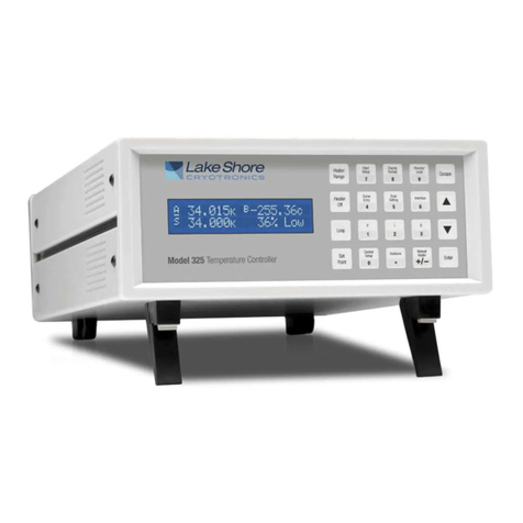
Lake Shore 335 User manual

User’s Manual
Model 335
Temperature Controller
Lake Shore Cryotronics, Inc.
575 McCorkle Blvd.
Westerville, Ohio 43082-8888 USA
service@lakeshore.com
www.lakeshore.com
Fax: (614) 891-1392
Telephone: (614) 891-2243
| www.lakeshore.com
Methods and apparatus disclosed and described herein have been developed solely on company funds of
Lake Shore Cryotronics, Inc. No government or other contractual support or relationship whatsoever has existed
which in any way affects or mitigates proprietary rights of Lake Shore Cryotronics, Inc. in these developments.
Methods and apparatus disclosed herein may be subject to U.S. Patents existing or applied for.
Lake Shore Cryotronics, Inc. reserves the right to add, improve, modify, or withdraw functions, design modifications,
or products at any time without notice. Lake Shore shall not be liable for errors contained herein or for incidental or
consequential damages in connection with furnishing, performance, or use of this material.
Rev. 1.5 P/N 119-055 25 July 2017

Model 335 Temperature Controller
LIMITED WARRANTY STATEMENT
WARRANTY PERIOD: THREE (3) YEARS
1.Lake Shore warrants that products manufactured by Lake Shore (the
"Product") will be free from defects in materials and workmanship for
three years from the date of Purchaser's physical receipt of the Prod-
uct (the "Warranty Period"). If Lake Shore receives notice of any such
defects during the Warranty Period and the defective Product is
shipped freight prepaid back to Lake Shore, Lake Shore will, at its
option, either repair or replace the Product (if it is so defective) with-
out charge for parts, service labor or associated customary return
shipping cost to the Purchaser. Replacement for the Product may be
by either new or equivalent in performance to new. Replacement or
repaired parts, or a replaced Product, will be warranted for only the
unexpired portion of the original warranty or 90 days (whichever is
greater).
2.Lake Shore warrants the Product only if the Product has been sold
by an authorized Lake Shore employee, sales representative, dealer or
an authorized Lake Shore original equipment manufacturer (OEM).
3.The Product may contain remanufactured parts equivalent to new
in performance or may have been subject to incidental use when it is
originally sold to the Purchaser.
4.The Warranty Period begins on the date the Product ships from Lake
Shore’s plant.
5.This limited warranty does not apply to defects in the Product
resulting from (a) improper or inadequate installation (unless OT&V
services are performed by Lake Shore), maintenance, repair or cali-
bration, (b) fuses, software, power surges, lightning and non-
rechargeable batteries, (c) software, interfacing, parts or other sup-
plies not furnished by Lake Shore, (d) unauthorized modification or
misuse, (e) operation outside of the published specifications, (f)
improper site preparation or site maintenance (g) natural disasters
such as flood, fire, wind, or earthquake, or (h) damage during ship-
ment other than original shipment to you if shipped through a Lake
Shore carrier.
6.This limited warranty does not cover: (a) regularly scheduled or ordi-
nary and expected recalibrations of the Product; (b) accessories to the
Product (such as probe tips and cables, holders, wire, grease, varnish,
feedthroughs, etc.); (c) consumables used in conjunction with the
Product (such as probe tips and cables, probe holders, sample tails,
rods and holders, ceramic putty for mounting samples, Hall sample
cards, Hall sample enclosures, etc.); or, (d) non-Lake Shore branded
Products that are integrated with the Product.
7. To the extent allowed by applicable law, this limited warranty is the
only warranty applicable to the Product and replaces all other war-
ranties or conditions, express or implied, including, but not limited to,
the implied warranties or conditions of merchantability and fitness
for a particular purpose. Specifically, except as provided herein, Lake
Shore undertakes no responsibility that the products will be fit for any
particular purpose for which you may be buying the Products. Any
implied warranty is limited in duration to the warranty period. No oral
or written information, or advice given by the Company, its Agents or
Employees, shall create a warranty or in any way increase the scope of
this limited warranty. Some countries, states or provinces do not
allow limitations on an implied warranty, so the above limitation or
exclusion might not apply to you. This warranty gives you specific
legal rights and you might also have other rights that vary from coun-
try to country, state to state or province to province.
8.Further, with regard to the United Nations Convention for Interna-
tional Sale of Goods (CISC,) if CISG is found to apply in relation to this
agreement, which is specifically disclaimed by Lake Shore, then this
limited warranty excludes warranties that: (a) the Product is fit for the
purpose for which goods of the same description would ordinarily be
used, (b) the Product is fit for any particular purpose expressly or
impliedly made known to Lake Shore at the time of the conclusion of
the contract. (c) the Product is contained or packaged in a manner
usual for such goods or in a manner adequate to preserve and protect
such goods where it is shipped by someone other than a carrier hired
by Lake Shore.
9. Lake Shore disclaims any warranties of technological value or of
non-infringement with respect to the Product and Lake Shore shall
have no duty to defend, indemnify, or hold harmless you from and
against any or all damages or costs incurred by you arising from the
infringement of patents or trademarks or violation or copyrights by
the Product.
10.THIS WARRANTY IS NOT TRANSFERRABLE. This warranty is not
transferrable.
11.Except to the extent prohibited by applicable law, neither Lake
Shore nor any of its subsidiaries, affiliates or suppliers will be held lia-
ble for direct, special, incidental, consequential or other damages
(including lost profit, lost data, or downtime costs) arising out of the
use, inability to use or result of use of the product, whether based in
warranty, contract, tort or other legal theory, regardless whether or
not Lake Shore has been advised of the possibility of such damages.
Purchaser's use of the Product is entirely at Purchaser's risk. Some
countries, states and provinces do not allow the exclusion of liability
for incidental or consequential damages, so the above limitation may
not apply to you.
12.This limited warranty gives you specific legal rights, and you may
also have other rights that vary within or between jurisdictions where
the product is purchased and/or used. Some jurisdictions do not allow
limitation in certain warranties, and so the above limitations or exclu-
sions of some warranties stated above may not apply to you.
13.Except to the extent allowed by applicable law, the terms of this
limited warranty statement do not exclude, restrict or modify the
mandatory statutory rights applicable to the sale of the product
to you.
| www.lakeshore.com
CERTIFICATION
Lake Shore certifies that this product has been inspected and tested
in accordance with its published specifications and that this product
met its published specifications at the time of shipment. The accu-
racy and calibration of this product at the time of shipment are trace-
able to the United States National Institute of Standards and
Technology (NIST); formerly known as the National Bureau of Stan-
dards (NBS).
FIRMWARE LIMITATIONS
Lake Shore has worked to ensure that the Model 335 firmware is as
free of errors as possible, and that the results you obtain from the
instrument are accurate and reliable. However, as with any com-
puter-based software, the possibility of errors exists.
In any important research, as when using any laboratory equipment,
results should be carefully examined and rechecked before final con-
clusions are drawn. Neither Lake Shore nor anyone else involved in
the creation or production of this firmware can pay for loss of time,
inconvenience, loss of use of the product, or property damage caused
by this product or its failure to work, or any other incidental or conse-
quential damages. Use of our product implies that you understand
the Lake Shore license agreement and statement of limited warranty.
FIRMWARE LICENSE AGREEMENT
The firmware in this instrument is protected by United States copy-
right law and international treaty provisions. To maintain the war-
ranty, the code contained in the firmware must not be modified. Any
changes made to the code is at the user's risk. Lake Shore will assume
no responsibility for damage or errors incurred as result of any
changes made to the firmware.
FIRMWARE LICENSE AGREEMENT (continued)
Under the terms of this agreement you may only use the Model 335
firmware as physically installed in the instrument. Archival copies are
strictly forbidden. You may not decompile, disassemble, or reverse
engineer the firmware. If you suspect there are problems with the
firmware, return the instrument to Lake Shore for repair under the
terms of the Limited Warranty specified above. Any unauthorized
duplication or use of the Model 335 firmware in whole or in part, in
print, or in any other storage and retrieval system is forbidden.
TRADEMARK ACKNOWLEDGMENT
Many manufacturers and sellers claim designations used to distin-
guish their products as trademarks. Where those designations
appear in this manual and Lake Shore was aware of a trademark
claim, they appear with initial capital letters and the ™ or ® symbol.
Alumel™ and Chromel™ are trademarks of
Conceptech, Inc., Corporation
Apiezon™ is a registered trademark of M&I Materials, Ltd.
CalCurve™, Cernox™, SoftCal™, Rox™, Curve Handler™ are trade-
marks of Lake Shore Cryotronics, Inc.
Java™ is a registered trademark of Sun Microsystems, Inc.
of Santa Clara, CA
LabVIEW® is a registered trademark of National Instruments.
Mac® is a registered trademark of Apple, Inc., registered in the U.S and
other countries.
Microsoft Windows®, Excel®, and Windows Vista® are registered
trademarks of Microsoft Corporation in the United States and other
countries.
Stycast® is a trademark of Emerson & Cuming.
WinZip™ is a registered trademark of Nico Mak of Connecticut.
Copyright 2011 - 2017 Lake Shore Cryotronics, Inc. All rights reserved. No portion of this manual may be
reproduced, stored in a retrieval system, or transmitted, in any form or by any means, electronic, mechanical,
photocopying, recording, or otherwise, without the express written permission of Lake Shore.

EU DECLARATION OF CONFORMITY
This declaration of conformity is issued under the sole responsibility of the manufacturer.
Manufacturer:
Lake Shore Cryotronics, Inc.
575 McCorkle Boulevard
Westerville, OH 43082
USA
Object of the declaration:
Model(s): 335
Description: Cryogenic Temperature Controller
The object of the declaration described above is in conformity with the relevant Union harmonization
legislation:
2014/35/EU Low Voltage Directive
2014/30/EU EMC Directive
2011/65/EU RoHS
References to the relevant harmonized standards used to the specification in relation to which
conformity is declared:
EN 61010-1:2010
Overvoltage Category II
Pollution Degree 2
EN 61326-1:2013
Class A
Controlled Electromagnetic Environment
EN 50581:2012
Signed for and on behalf of:
Place, Date:
Westerville, OH USA Scott Ayer
29-SEP-2016 Director of Quality & Compliance
Model 335 Temperature Controller

| www.lakeshore.com
Electromagnetic Compatibility (EMC) for the Model 335 Temperature Controller
Electromagnetic Compatibility (EMC) of electronic equipment is a growing concern worldwide. Emissions of and
immunity to electromagnetic interference is now part of the design and manufacture of most electronics. To qualify
for the CE Mark, the Model 335 meets or exceeds the requirements of the European EMC Directive 89/335/EEC as a
CLASS A product. A Class A product is allowed to radiate more RF than a Class B product and must include the follow-
ing warning:
WARNING: This is a Class A product. In a domestic environment, this product may cause radio interference in which
case the user may be required to take adequate measures.
The instrument was tested under normal operating conditions with sensor and interface cables attached. If the
installation and operating instructions in the User's Manual are followed, there should be no degradation in EMC
performance.
This instrument is not intended for use in close proximity to RF transmitters such as two-way radios and cell
phones. Exposure to RF interference greater than that found in a typical laboratory environment may disturb the
sensitive measurement circuitry of the instrument.
Pay special attention to instrument cabling. Improperly installed cabling may defeat even the best EMC protection.
For the best performance from any precision instrument, follow the grounding and shielding instructions in the
User's Manual. In addition, the installer of the Model 335 should consider the following:
DShield measurement and computer interface cables.
DLeave no unused or unterminated cables attached to the instrument.
DMake cable runs as short and direct as possible. Higher radiated emissions are possible with long cables.
DDo not tightly bundle cables that carry different types of signals.

Model 335 Temperature Controller

i
| www.lakeshore.com
Table of Contents
Chapter 1
Introduction
1.1 Product Description . . . . . . . . . . . . . . . . . . . . . . . . . . . . . . . . . . . . . . . . . . . . . . . . . . . . . . . . . . . . . . . . . . 1
1.1.1 Sensor Inputs . . . . . . . . . . . . . . . . . . . . . . . . . . . . . . . . . . . . . . . . . . . . . . . . . . . . . . . . . . . . . . . . . . 2
1.1.2 Temperature Control . . . . . . . . . . . . . . . . . . . . . . . . . . . . . . . . . . . . . . . . . . . . . . . . . . . . . . . . . . 3
1.1.3 Interface . . . . . . . . . . . . . . . . . . . . . . . . . . . . . . . . . . . . . . . . . . . . . . . . . . . . . . . . . . . . . . . . . . . . . . . 3
1.1.4 Configurable Display . . . . . . . . . . . . . . . . . . . . . . . . . . . . . . . . . . . . . . . . . . . . . . . . . . . . . . . . . . 4
1.1.5 Model 3060 Thermocouple Input Option . . . . . . . . . . . . . . . . . . . . . . . . . . . . . . . . . . . . . 4
1.2 Sensor Selection . . . . . . . . . . . . . . . . . . . . . . . . . . . . . . . . . . . . . . . . . . . . . . . . . . . . . . . . . . . . . . . . . . . . . . 5
1.3 Model 335 Specifications . . . . . . . . . . . . . . . . . . . . . . . . . . . . . . . . . . . . . . . . . . . . . . . . . . . . . . . . . . . . 7
1.3.1 Input Specifications . . . . . . . . . . . . . . . . . . . . . . . . . . . . . . . . . . . . . . . . . . . . . . . . . . . . . . . . . . . 7
1.3.2 Sensor Input Configuration . . . . . . . . . . . . . . . . . . . . . . . . . . . . . . . . . . . . . . . . . . . . . . . . . . . . 8
1.3.3 Thermometry . . . . . . . . . . . . . . . . . . . . . . . . . . . . . . . . . . . . . . . . . . . . . . . . . . . . . . . . . . . . . . . . . . 8
1.3.4 Control . . . . . . . . . . . . . . . . . . . . . . . . . . . . . . . . . . . . . . . . . . . . . . . . . . . . . . . . . . . . . . . . . . . . . . . . . 8
1.3.4.1 Heater Outputs (Outputs 1 and 2) . . . . . . . . . . . . . . . . . . . . . . . . . . . . . . . . . . . . 8
1.3.5 Front Panel . . . . . . . . . . . . . . . . . . . . . . . . . . . . . . . . . . . . . . . . . . . . . . . . . . . . . . . . . . . . . . . . . . . .10
1.3.6 Interface . . . . . . . . . . . . . . . . . . . . . . . . . . . . . . . . . . . . . . . . . . . . . . . . . . . . . . . . . . . . . . . . . . . . . . 10
1.3.7 General . . . . . . . . . . . . . . . . . . . . . . . . . . . . . . . . . . . . . . . . . . . . . . . . . . . . . . . . . . . . . . . . . . . . . . . . 10
1.4 Safety Summary and Symbols . . . . . . . . . . . . . . . . . . . . . . . . . . . . . . . . . . . . . . . . . . . . . . . . . . . . . . 11
Chapter 2
Cooling System
Design and
Temperature
Control
2.1 General . . . . . . . . . . . . . . . . . . . . . . . . . . . . . . . . . . . . . . . . . . . . . . . . . . . . . . . . . . . . . . . . . . . . . . . . . . . . . . .13
2.2 Temperature Sensor Selection . . . . . . . . . . . . . . . . . . . . . . . . . . . . . . . . . . . . . . . . . . . . . . . . . . . . . .13
2.2.1 Temperature Range . . . . . . . . . . . . . . . . . . . . . . . . . . . . . . . . . . . . . . . . . . . . . . . . . . . . . . . . . .13
2.2.2 Sensor Sensitivity . . . . . . . . . . . . . . . . . . . . . . . . . . . . . . . . . . . . . . . . . . . . . . . . . . . . . . . . . . . . .13
2.2.3 Environmental Conditions . . . . . . . . . . . . . . . . . . . . . . . . . . . . . . . . . . . . . . . . . . . . . . . . . . .14
2.2.4 Measurement Accuracy . . . . . . . . . . . . . . . . . . . . . . . . . . . . . . . . . . . . . . . . . . . . . . . . . . . . . . 14
2.2.5 Sensor Package . . . . . . . . . . . . . . . . . . . . . . . . . . . . . . . . . . . . . . . . . . . . . . . . . . . . . . . . . . . . . . . 14
2.3 Sensor Calibrations . . . . . . . . . . . . . . . . . . . . . . . . . . . . . . . . . . . . . . . . . . . . . . . . . . . . . . . . . . . . . . . . . 14
2.3.1 Precision Calibration . . . . . . . . . . . . . . . . . . . . . . . . . . . . . . . . . . . . . . . . . . . . . . . . . . . . . . . . .15
2.3.2 SoftCal™ . . . . . . . . . . . . . . . . . . . . . . . . . . . . . . . . . . . . . . . . . . . . . . . . . . . . . . . . . . . . . . . . . . . . . .15
2.3.3 Sensors Using Standard Curves . . . . . . . . . . . . . . . . . . . . . . . . . . . . . . . . . . . . . . . . . . . . . .15
2.3.4 Curve Handler™ . . . . . . . . . . . . . . . . . . . . . . . . . . . . . . . . . . . . . . . . . . . . . . . . . . . . . . . . . . . . . .15
2.4 Sensor Installation . . . . . . . . . . . . . . . . . . . . . . . . . . . . . . . . . . . . . . . . . . . . . . . . . . . . . . . . . . . . . . . . . . .16
2.4.1 Mounting Materials . . . . . . . . . . . . . . . . . . . . . . . . . . . . . . . . . . . . . . . . . . . . . . . . . . . . . . . . . .16
2.4.2 Sensor Location . . . . . . . . . . . . . . . . . . . . . . . . . . . . . . . . . . . . . . . . . . . . . . . . . . . . . . . . . . . . . . . 16
2.4.3 Thermal Conductivity . . . . . . . . . . . . . . . . . . . . . . . . . . . . . . . . . . . . . . . . . . . . . . . . . . . . . . . . 16
2.4.4 Contact Area . . . . . . . . . . . . . . . . . . . . . . . . . . . . . . . . . . . . . . . . . . . . . . . . . . . . . . . . . . . . . . . . . .17
2.4.5 Contact Pressure . . . . . . . . . . . . . . . . . . . . . . . . . . . . . . . . . . . . . . . . . . . . . . . . . . . . . . . . . . . . . . 17
2.4.6 Lead Wire . . . . . . . . . . . . . . . . . . . . . . . . . . . . . . . . . . . . . . . . . . . . . . . . . . . . . . . . . . . . . . . . . . . . .17
2.4.7 Lead Soldering . . . . . . . . . . . . . . . . . . . . . . . . . . . . . . . . . . . . . . . . . . . . . . . . . . . . . . . . . . . . . . . .18
2.4.8 Thermal Anchoring Leads . . . . . . . . . . . . . . . . . . . . . . . . . . . . . . . . . . . . . . . . . . . . . . . . . . . .18
2.4.9 Thermal Radiation . . . . . . . . . . . . . . . . . . . . . . . . . . . . . . . . . . . . . . . . . . . . . . . . . . . . . . . . . . . .19
2.5 Heater Selection and Installation . . . . . . . . . . . . . . . . . . . . . . . . . . . . . . . . . . . . . . . . . . . . . . . . . . .19
2.5.1 Heater Resistance and Power . . . . . . . . . . . . . . . . . . . . . . . . . . . . . . . . . . . . . . . . . . . . . . . . 19
2.5.2 Heater Location . . . . . . . . . . . . . . . . . . . . . . . . . . . . . . . . . . . . . . . . . . . . . . . . . . . . . . . . . . . . . . . 20
2.5.3 Heater Types . . . . . . . . . . . . . . . . . . . . . . . . . . . . . . . . . . . . . . . . . . . . . . . . . . . . . . . . . . . . . . . . . . 20
2.5.4 Heater Wiring . . . . . . . . . . . . . . . . . . . . . . . . . . . . . . . . . . . . . . . . . . . . . . . . . . . . . . . . . . . . . . . . .21
2.6 Consideration for Good Control . . . . . . . . . . . . . . . . . . . . . . . . . . . . . . . . . . . . . . . . . . . . . . . . . . . . .21
2.6.1 Thermal Conductivity . . . . . . . . . . . . . . . . . . . . . . . . . . . . . . . . . . . . . . . . . . . . . . . . . . . . . . . . 21
2.6.2 Thermal Lag . . . . . . . . . . . . . . . . . . . . . . . . . . . . . . . . . . . . . . . . . . . . . . . . . . . . . . . . . . . . . . . . . . .21
2.6.3 Two-Sensor Approach . . . . . . . . . . . . . . . . . . . . . . . . . . . . . . . . . . . . . . . . . . . . . . . . . . . . . . . . 21
2.6.4 Thermal Mass . . . . . . . . . . . . . . . . . . . . . . . . . . . . . . . . . . . . . . . . . . . . . . . . . . . . . . . . . . . . . . . . .22
2.6.5 System Non-Linearity . . . . . . . . . . . . . . . . . . . . . . . . . . . . . . . . . . . . . . . . . . . . . . . . . . . . . . . .22

Model 335 Temperature Controller
2.7 PID Control . . . . . . . . . . . . . . . . . . . . . . . . . . . . . . . . . . . . . . . . . . . . . . . . . . . . . . . . . . . . . . . . . . . . . . . . . . 22
2.7.1 Proportional (P) . . . . . . . . . . . . . . . . . . . . . . . . . . . . . . . . . . . . . . . . . . . . . . . . . . . . . . . . . . . . . . . 23
2.7.2 Integral (I) . . . . . . . . . . . . . . . . . . . . . . . . . . . . . . . . . . . . . . . . . . . . . . . . . . . . . . . . . . . . . . . . . . . . . 23
2.7.3 Derivative (D) . . . . . . . . . . . . . . . . . . . . . . . . . . . . . . . . . . . . . . . . . . . . . . . . . . . . . . . . . . . . . . . . . 23
2.7.4 Manual Output . . . . . . . . . . . . . . . . . . . . . . . . . . . . . . . . . . . . . . . . . . . . . . . . . . . . . . . . . . . . . . . 23
2.8 Manual Tuning . . . . . . . . . . . . . . . . . . . . . . . . . . . . . . . . . . . . . . . . . . . . . . . . . . . . . . . . . . . . . . . . . . . . . . 25
2.8.1 Setting Heater Range . . . . . . . . . . . . . . . . . . . . . . . . . . . . . . . . . . . . . . . . . . . . . . . . . . . . . . . . . 25
2.8.2 Tuning Proportional . . . . . . . . . . . . . . . . . . . . . . . . . . . . . . . . . . . . . . . . . . . . . . . . . . . . . . . . . . 25
2.8.3 Tuning Integral . . . . . . . . . . . . . . . . . . . . . . . . . . . . . . . . . . . . . . . . . . . . . . . . . . . . . . . . . . . . . . . 26
2.8.4 Tuning Derivative . . . . . . . . . . . . . . . . . . . . . . . . . . . . . . . . . . . . . . . . . . . . . . . . . . . . . . . . . . . . . 27
2.9 Autotuning . . . . . . . . . . . . . . . . . . . . . . . . . . . . . . . . . . . . . . . . . . . . . . . . . . . . . . . . . . . . . . . . . . . . . . . . . . 27
2.10 Zone Tuning . . . . . . . . . . . . . . . . . . . . . . . . . . . . . . . . . . . . . . . . . . . . . . . . . . . . . . . . . . . . . . . . . . . . . . . . 28
2.11 Thermoelectric Devices . . . . . . . . . . . . . . . . . . . . . . . . . . . . . . . . . . . . . . . . . . . . . . . . . . . . . . . . . . . . 28
Chapter 3
Installation
3.1 General . . . . . . . . . . . . . . . . . . . . . . . . . . . . . . . . . . . . . . . . . . . . . . . . . . . . . . . . . . . . . . . . . . . . . . . . . . . . . . 29
3.2 Inspection and Unpacking . . . . . . . . . . . . . . . . . . . . . . . . . . . . . . . . . . . . . . . . . . . . . . . . . . . . . . . . . . 29
3.3 Rear Panel Definition . . . . . . . . . . . . . . . . . . . . . . . . . . . . . . . . . . . . . . . . . . . . . . . . . . . . . . . . . . . . . . . . 30
3.4 Line Input Assembly . . . . . . . . . . . . . . . . . . . . . . . . . . . . . . . . . . . . . . . . . . . . . . . . . . . . . . . . . . . . . . . . . 30
3.4.1 Line Voltage . . . . . . . . . . . . . . . . . . . . . . . . . . . . . . . . . . . . . . . . . . . . . . . . . . . . . . . . . . . . . . . . . . . 30
3.4.2 Line Fuse and Fuse Holder . . . . . . . . . . . . . . . . . . . . . . . . . . . . . . . . . . . . . . . . . . . . . . . . . . . . 31
3.4.3 Power Cord . . . . . . . . . . . . . . . . . . . . . . . . . . . . . . . . . . . . . . . . . . . . . . . . . . . . . . . . . . . . . . . . . . . 31
3.4.4 Power Switch . . . . . . . . . . . . . . . . . . . . . . . . . . . . . . . . . . . . . . . . . . . . . . . . . . . . . . . . . . . . . . . . . 31
3.5 Diode/Resistor Sensor Inputs . . . . . . . . . . . . . . . . . . . . . . . . . . . . . . . . . . . . . . . . . . . . . . . . . . . . . . . 31
3.5.1 Sensor Input Connector and Pinout . . . . . . . . . . . . . . . . . . . . . . . . . . . . . . . . . . . . . . . . . . 31
3.5.2 Sensor Lead Cable . . . . . . . . . . . . . . . . . . . . . . . . . . . . . . . . . . . . . . . . . . . . . . . . . . . . . . . . . . . . 32
3.5.3 Grounding and Shielding Sensor Leads . . . . . . . . . . . . . . . . . . . . . . . . . . . . . . . . . . . . . . 32
3.5.4 Sensor Polarity . . . . . . . . . . . . . . . . . . . . . . . . . . . . . . . . . . . . . . . . . . . . . . . . . . . . . . . . . . . . . . . . 33
3.5.5 Four-Lead Sensor Measurement . . . . . . . . . . . . . . . . . . . . . . . . . . . . . . . . . . . . . . . . . . . . . 33
3.5.6 Two-Lead Sensor Measurement . . . . . . . . . . . . . . . . . . . . . . . . . . . . . . . . . . . . . . . . . . . . . 34
3.5.7 Lowering Measurement Noise . . . . . . . . . . . . . . . . . . . . . . . . . . . . . . . . . . . . . . . . . . . . . . . 34
3.6 Thermocouple Sensor Inputs (Thermocouple Model 3060) . . . . . . . . . . . . . . . . . . . . . . . 35
3.6.1 Sensor Input Terminals . . . . . . . . . . . . . . . . . . . . . . . . . . . . . . . . . . . . . . . . . . . . . . . . . . . . . . . 35
3.6.2 Thermocouple Installation . . . . . . . . . . . . . . . . . . . . . . . . . . . . . . . . . . . . . . . . . . . . . . . . . . . 35
3.6.3 Grounding and Shielding . . . . . . . . . . . . . . . . . . . . . . . . . . . . . . . . . . . . . . . . . . . . . . . . . . . . . 35
3.7 Heater Output Setup . . . . . . . . . . . . . . . . . . . . . . . . . . . . . . . . . . . . . . . . . . . . . . . . . . . . . . . . . . . . . . . . 36
3.7.1 Heater Output Description . . . . . . . . . . . . . . . . . . . . . . . . . . . . . . . . . . . . . . . . . . . . . . . . . . . 36
3.7.2 Heater Output Connectors . . . . . . . . . . . . . . . . . . . . . . . . . . . . . . . . . . . . . . . . . . . . . . . . . . . 36
3.7.3 Heater Output Wiring . . . . . . . . . . . . . . . . . . . . . . . . . . . . . . . . . . . . . . . . . . . . . . . . . . . . . . . . 36
3.7.4 Heater Output Noise . . . . . . . . . . . . . . . . . . . . . . . . . . . . . . . . . . . . . . . . . . . . . . . . . . . . . . . . . 37
3.7.5 Powering Output 2 Using an External Power Supply . . . . . . . . . . . . . . . . . . . . . . . . 37
3.7.5.1 Choosing a Power Supply . . . . . . . . . . . . . . . . . . . . . . . . . . . . . . . . . . . . . . . . . . . . 37
3.7.5.2 Power Supply Setup . . . . . . . . . . . . . . . . . . . . . . . . . . . . . . . . . . . . . . . . . . . . . . . . . . 38
3.7.5.3 Connecting to the Model 335 . . . . . . . . . . . . . . . . . . . . . . . . . . . . . . . . . . . . . . . . 38
3.7.5.4 Programming Voltages Under 10 V . . . . . . . . . . . . . . . . . . . . . . . . . . . . . . . . . . 39

iii
| www.lakeshore.com
Chapter 4
Operation
4.1 General . . . . . . . . . . . . . . . . . . . . . . . . . . . . . . . . . . . . . . . . . . . . . . . . . . . . . . . . . . . . . . . . . . . . . . . . . . . . . . .41
4.1.1 Understanding Menu Navigation . . . . . . . . . . . . . . . . . . . . . . . . . . . . . . . . . . . . . . . . . . . 41
4.2 Front Panel Description. . . . . . . . . . . . . . . . . . . . . . . . . . . . . . . . . . . . . . . . . . . . . . . . . . . . . . . . . . . . . 42
4.2.1 Keypad Definitions . . . . . . . . . . . . . . . . . . . . . . . . . . . . . . . . . . . . . . . . . . . . . . . . . . . . . . . . . . . 42
4.2.1.1 Direct Operation Keys . . . . . . . . . . . . . . . . . . . . . . . . . . . . . . . . . . . . . . . . . . . . . . . .42
4.2.1.2 Menu/Number Pad Keys . . . . . . . . . . . . . . . . . . . . . . . . . . . . . . . . . . . . . . . . . . . . . 42
4.2.2 Annunciators . . . . . . . . . . . . . . . . . . . . . . . . . . . . . . . . . . . . . . . . . . . . . . . . . . . . . . . . . . . . . . . . . .43
4.2.3 General Keypad Operation . . . . . . . . . . . . . . . . . . . . . . . . . . . . . . . . . . . . . . . . . . . . . . . . . . .43
4.3 Display Setup . . . . . . . . . . . . . . . . . . . . . . . . . . . . . . . . . . . . . . . . . . . . . . . . . . . . . . . . . . . . . . . . . . . . . . . . 44
4.3.1 Display Modes . . . . . . . . . . . . . . . . . . . . . . . . . . . . . . . . . . . . . . . . . . . . . . . . . . . . . . . . . . . . . . . .44
4.3.1.1 Two Input, One Loop Modes . . . . . . . . . . . . . . . . . . . . . . . . . . . . . . . . . . . . . . . . . .44
4.3.1.2 Two Loop Mode . . . . . . . . . . . . . . . . . . . . . . . . . . . . . . . . . . . . . . . . . . . . . . . . . . . . . . . 45
4.3.1.3 Input Display Modes . . . . . . . . . . . . . . . . . . . . . . . . . . . . . . . . . . . . . . . . . . . . . . . . . .45
4.3.1.4 Custom Display Mode . . . . . . . . . . . . . . . . . . . . . . . . . . . . . . . . . . . . . . . . . . . . . . . . 46
4.3.2 Display Brightness . . . . . . . . . . . . . . . . . . . . . . . . . . . . . . . . . . . . . . . . . . . . . . . . . . . . . . . . . . . .47
4.4 Input Setup . . . . . . . . . . . . . . . . . . . . . . . . . . . . . . . . . . . . . . . . . . . . . . . . . . . . . . . . . . . . . . . . . . . . . . . . . .47
4.4.1 Diode Sensor Input Setup . . . . . . . . . . . . . . . . . . . . . . . . . . . . . . . . . . . . . . . . . . . . . . . . . . . . .48
4.4.2 Positive Temperature Coefficient (PTC) Resistor Sensor Input Setup . . . . . . . 48
4.4.3 Negative Temperature Coefficient (NTC) Resistor Sensor Input Setup . . . . . 48
4.4.4 Range Selection . . . . . . . . . . . . . . . . . . . . . . . . . . . . . . . . . . . . . . . . . . . . . . . . . . . . . . . . . . . . . . . 49
4.4.5 Thermal Electromotive Force (EMF) Compensation . . . . . . . . . . . . . . . . . . . . . . . . 49
4.4.6 Thermocouple Sensor Input Setup (Model 3060 Only) . . . . . . . . . . . . . . . . . . . . . .50
4.4.6.1 Internal Room Temperature Compensation . . . . . . . . . . . . . . . . . . . . . . . . .50
4.4.6.2 Internal Room Temperature Compensation Calibration Procedure 50
4.4.7 Curve Selection . . . . . . . . . . . . . . . . . . . . . . . . . . . . . . . . . . . . . . . . . . . . . . . . . . . . . . . . . . . . . . .51
4.4.8 Filter . . . . . . . . . . . . . . . . . . . . . . . . . . . . . . . . . . . . . . . . . . . . . . . . . . . . . . . . . . . . . . . . . . . . . . . . . . .52
4.4.9 Input Sensor Name . . . . . . . . . . . . . . . . . . . . . . . . . . . . . . . . . . . . . . . . . . . . . . . . . . . . . . . . . . .53
4.4.10 Temperature Limit . . . . . . . . . . . . . . . . . . . . . . . . . . . . . . . . . . . . . . . . . . . . . . . . . . . . . . . . . .53
4.4.11 Preferred Units . . . . . . . . . . . . . . . . . . . . . . . . . . . . . . . . . . . . . . . . . . . . . . . . . . . . . . . . . . . . . . 54
4.4.12 Max/Min . . . . . . . . . . . . . . . . . . . . . . . . . . . . . . . . . . . . . . . . . . . . . . . . . . . . . . . . . . . . . . . . . . . . .54
4.5 Output and Control Setup . . . . . . . . . . . . . . . . . . . . . . . . . . . . . . . . . . . . . . . . . . . . . . . . . . . . . . . . . . .54
4.5.1 Heater Outputs . . . . . . . . . . . . . . . . . . . . . . . . . . . . . . . . . . . . . . . . . . . . . . . . . . . . . . . . . . . . . . .54
4.5.1.1 Heater Output Type (Output 2) . . . . . . . . . . . . . . . . . . . . . . . . . . . . . . . . . . . . . .55
4.5.1.2 75 W Configuration . . . . . . . . . . . . . . . . . . . . . . . . . . . . . . . . . . . . . . . . . . . . . . . . . .55
4.5.1.3 Max Current and Heater Resistance . . . . . . . . . . . . . . . . . . . . . . . . . . . . . . . . . 55
4.5.1.3.1 User Max Current . . . . . . . . . . . . . . . . . . . . . . . . . . . . . . . . . . . . . . . . . .56
4.5.1.4 Power Up Enable . . . . . . . . . . . . . . . . . . . . . . . . . . . . . . . . . . . . . . . . . . . . . . . . . . . . . 57
4.5.1.5 Heater Out Display . . . . . . . . . . . . . . . . . . . . . . . . . . . . . . . . . . . . . . . . . . . . . . . . . . . 58
4.5.1.6 Output Modes . . . . . . . . . . . . . . . . . . . . . . . . . . . . . . . . . . . . . . . . . . . . . . . . . . . . . . . . 58
4.5.1.6.1 Closed Loop PID Mode . . . . . . . . . . . . . . . . . . . . . . . . . . . . . . . . . . . . .58
4.5.1.6.2 Zone Mode 5 . . . . . . . . . . . . . . . . . . . . . . . . . . . . . . . . . . . . . . . . . . . . . . . . . 8
4.5.1.6.3 Open Loop Mode . . . . . . . . . . . . . . . . . . . . . . . . . . . . . . . . . . . . . . . . . . . 59
4.5.1.7 Control Parameters . . . . . . . . . . . . . . . . . . . . . . . . . . . . . . . . . . . . . . . . . . . . . . . . . . . 59
4.5.1.7.1 Control Input . . . . . . . . . . . . . . . . . . . . . . . . . . . . . . . . . . . . . . . . . . . . . . . 59
4.5.1.7.2 Proportional (P) . . . . . . . . . . . . . . . . . . . . . . . . . . . . . . . . . . . . . . . . . . . . 60
4.5.1.7.3 Integral (I) . . . . . . . . . . . . . . . . . . . . . . . . . . . . . . . . . . . . . . . . . . . . . . . . . .60
4.5.1.7.4 Derivative (D) . . . . . . . . . . . . . . . . . . . . . . . . . . . . . . . . . . . . . . . . . . . . . . . 61
4.5.1.7.5 Manual Output . . . . . . . . . . . . . . . . . . . . . . . . . . . . . . . . . . . . . . . . . . . . .61
4.5.1.7.6 Setpoint . . . . . . . . . . . . . . . . . . . . . . . . . . . . . . . . . . . . . . . . . . . . . . . . . . . . 62
4.5.1.7.7 Setpoint Ramping . . . . . . . . . . . . . . . . . . . . . . . . . . . . . . . . . . . . . . . . . .63
4.5.1.7.8 Heater Range . . . . . . . . . . . . . . . . . . . . . . . . . . . . . . . . . . . . . . . . . . . . . . .64
4.5.1.7.9 ALL OFF . . . . . . . . . . . . . . . . . . . . . . . . . . . . . . . . . . . . . . . . . . . . . . . . . . . . .64
4.5.2 Voltage Output . . . . . . . . . . . . . . . . . . . . . . . . . . . . . . . . . . . . . . . . . . . . . . . . . . . . . . . . . . . . . . . .64
4.5.2.1 Warm Up Supply . . . . . . . . . . . . . . . . . . . . . . . . . . . . . . . . . . . . . . . . . . . . . . . . . . . . .65
4.5.2.2 Monitor Out . . . . . . . . . . . . . . . . . . . . . . . . . . . . . . . . . . . . . . . . . . . . . . . . . . . . . . . . . .65

Model 335 Temperature Controller
4.6 Interface . . . . . . . . . . . . . . . . . . . . . . . . . . . . . . . . . . . . . . . . . . . . . . . . . . . . . . . . . . . . . . . . . . . . . . . . . . . . . 65
4.6.1 USB . . . . . . . . . . . . . . . . . . . . . . . . . . . . . . . . . . . . . . . . . . . . . . . . . . . . . . . . . . . . . . . . . . . . . . . . . . . . 65
4.6.2 IEEE-488 . . . . . . . . . . . . . . . . . . . . . . . . . . . . . . . . . . . . . . . . . . . . . . . . . . . . . . . . . . . . . . . . . . . . . . 65
4.6.2.1 Remote/Local . . . . . . . . . . . . . . . . . . . . . . . . . . . . . . . . . . . . . . . . . . . . . . . . . . . . . . . . . 65
4.7 Locking and Unlocking the Keypad . . . . . . . . . . . . . . . . . . . . . . . . . . . . . . . . . . . . . . . . . . . . . . . . . 65
Chapter 5
Advanced
Operation
5.1 General . . . . . . . . . . . . . . . . . . . . . . . . . . . . . . . . . . . . . . . . . . . . . . . . . . . . . . . . . . . . . . . . . . . . . . . . . . . . . . 67
5.2 Autotune . . . . . . . . . . . . . . . . . . . . . . . . . . . . . . . . . . . . . . . . . . . . . . . . . . . . . . . . . . . . . . . . . . . . . . . . . . . . . 67
5.3 Zone Settings . . . . . . . . . . . . . . . . . . . . . . . . . . . . . . . . . . . . . . . . . . . . . . . . . . . . . . . . . . . . . . . . . . . . . . . . 69
5.4 Bipolar Control . . . . . . . . . . . . . . . . . . . . . . . . . . . . . . . . . . . . . . . . . . . . . . . . . . . . . . . . . . . . . . . . . . . . . . 71
5.5 Warm Up Supply . . . . . . . . . . . . . . . . . . . . . . . . . . . . . . . . . . . . . . . . . . . . . . . . . . . . . . . . . . . . . . . . . . . . 71
5.5.1 Warm Up Percentage . . . . . . . . . . . . . . . . . . . . . . . . . . . . . . . . . . . . . . . . . . . . . . . . . . . . . . . . . 72
5.5.2 Warm Up Control . . . . . . . . . . . . . . . . . . . . . . . . . . . . . . . . . . . . . . . . . . . . . . . . . . . . . . . . . . . . . 72
5.6 Monitor Out . . . . . . . . . . . . . . . . . . . . . . . . . . . . . . . . . . . . . . . . . . . . . . . . . . . . . . . . . . . . . . . . . . . . . . . . . 72
5.6.1 Monitor Units . . . . . . . . . . . . . . . . . . . . . . . . . . . . . . . . . . . . . . . . . . . . . . . . . . . . . . . . . . . . . . . . . 73
5.6.1.1 Polarity and Monitor Out Scaling Parameters . . . . . . . . . . . . . . . . . . . . . . 73
5.7 Alarms and Relays . . . . . . . . . . . . . . . . . . . . . . . . . . . . . . . . . . . . . . . . . . . . . . . . . . . . . . . . . . . . . . . . . . . 74
5.7.1 Alarms . . . . . . . . . . . . . . . . . . . . . . . . . . . . . . . . . . . . . . . . . . . . . . . . . . . . . . . . . . . . . . . . . . . . . . . . 74
5.7.1.1 Alarm Annunciators . . . . . . . . . . . . . . . . . . . . . . . . . . . . . . . . . . . . . . . . . . . . . . . . . . 74
5.7.1.2 Alarm Latching . . . . . . . . . . . . . . . . . . . . . . . . . . . . . . . . . . . . . . . . . . . . . . . . . . . . . . . 75
5.7.2 Relays . . . . . . . . . . . . . . . . . . . . . . . . . . . . . . . . . . . . . . . . . . . . . . . . . . . . . . . . . . . . . . . . . . . . . . . . . 76
5.8 Curve Numbers and Storage . . . . . . . . . . . . . . . . . . . . . . . . . . . . . . . . . . . . . . . . . . . . . . . . . . . . . . . . 77
5.8.1 Curve Header Parameters . . . . . . . . . . . . . . . . . . . . . . . . . . . . . . . . . . . . . . . . . . . . . . . . . . . . 77
5.8.2 Curve Breakpoints . . . . . . . . . . . . . . . . . . . . . . . . . . . . . . . . . . . . . . . . . . . . . . . . . . . . . . . . . . . . 77
5.9 Front Panel Curve Entry Operations . . . . . . . . . . . . . . . . . . . . . . . . . . . . . . . . . . . . . . . . . . . . . . . . 78
5.9.1 Edit Curve . . . . . . . . . . . . . . . . . . . . . . . . . . . . . . . . . . . . . . . . . . . . . . . . . . . . . . . . . . . . . . . . . . . . . 78
5.9.1.1 Edit a Breakpoint Pair . . . . . . . . . . . . . . . . . . . . . . . . . . . . . . . . . . . . . . . . . . . . . . . . 79
5.9.1.2 Add a New Breakpoint Pair . . . . . . . . . . . . . . . . . . . . . . . . . . . . . . . . . . . . . . . . . . . 80
5.9.1.3 Delete a Breakpoint Pair . . . . . . . . . . . . . . . . . . . . . . . . . . . . . . . . . . . . . . . . . . . . . 80
5.9.1.4 Thermocouple Curve Considerations . . . . . . . . . . . . . . . . . . . . . . . . . . . . . . . . 80
5.9.2 Erase Curve . . . . . . . . . . . . . . . . . . . . . . . . . . . . . . . . . . . . . . . . . . . . . . . . . . . . . . . . . . . . . . . . . . . 81
5.9.3 Copy Curve . . . . . . . . . . . . . . . . . . . . . . . . . . . . . . . . . . . . . . . . . . . . . . . . . . . . . . . . . . . . . . . . . . . . 81
5.10 SoftCal™ . . . . . . . . . . . . . . . . . . . . . . . . . . . . . . . . . . . . . . . . . . . . . . . . . . . . . . . . . . . . . . . . . . . . . . . . . . . 81
5.10.1 SoftCal™ with Silicon Diode Sensors . . . . . . . . . . . . . . . . . . . . . . . . . . . . . . . . . . . . . . . 82
5.10.2 SoftCal™ Accuracy with DT-400 Series Silicon Diode Sensors . . . . . . . . . . . . . 83
5.10.3 SoftCal™ With Platinum Sensors . . . . . . . . . . . . . . . . . . . . . . . . . . . . . . . . . . . . . . . . . . . 83
5.10.4 SoftCal™ Accuracy With Platinum Sensors . . . . . . . . . . . . . . . . . . . . . . . . . . . . . . . . 84
5.10.5 SoftCal™ CalibrationCurve Creation . . . . . . . . . . . . . . . . . . . . . . . . . . . . . . . . . . . . . . . 84
5.11 Emulation Modes . . . . . . . . . . . . . . . . . . . . . . . . . . . . . . . . . . . . . . . . . . . . . . . . . . . . . . . . . . . . . . . . . . 85
5.11.1 Emulation Mode Configuration . . . . . . . . . . . . . . . . . . . . . . . . . . . . . . . . . . . . . . . . . . . . 85
5.11.2 Unsupported Commands . . . . . . . . . . . . . . . . . . . . . . . . . . . . . . . . . . . . . . . . . . . . . . . . . . . 86
5.11.3 Command Interpretation . . . . . . . . . . . . . . . . . . . . . . . . . . . . . . . . . . . . . . . . . . . . . . . . . . . 86
5.11.4 PID Scaling Mode . . . . . . . . . . . . . . . . . . . . . . . . . . . . . . . . . . . . . . . . . . . . . . . . . . . . . . . . . . . 86
5.11.5 Baud Rate . . . . . . . . . . . . . . . . . . . . . . . . . . . . . . . . . . . . . . . . . . . . . . . . . . . . . . . . . . . . . . . . . . . 86
5.11.6 Hardware Differences . . . . . . . . . . . . . . . . . . . . . . . . . . . . . . . . . . . . . . . . . . . . . . . . . . . . . . . 87
5.11.7 Emulation Mode Differences . . . . . . . . . . . . . . . . . . . . . . . . . . . . . . . . . . . . . . . . . . . . . . . 87
Chapter 6
Computer
InterfaceOperation
6.1 General . . . . . . . . . . . . . . . . . . . . . . . . . . . . . . . . . . . . . . . . . . . . . . . . . . . . . . . . . . . . . . . . . . . . . . . . . . . . . . 89
6.2 IEEE-488 Interface . . . . . . . . . . . . . . . . . . . . . . . . . . . . . . . . . . . . . . . . . . . . . . . . . . . . . . . . . . . . . . . . . . 89
6.2.1 Changing IEEE-488 Interface Parameters . . . . . . . . . . . . . . . . . . . . . . . . . . . . . . . . . . . 90
6.2.2 Remote/Local Operation . . . . . . . . . . . . . . . . . . . . . . . . . . . . . . . . . . . . . . . . . . . . . . . . . . . . . 90
6.2.3 IEEE-488.2 Command Structure . . . . . . . . . . . . . . . . . . . . . . . . . . . . . . . . . . . . . . . . . . . . . 90
6.2.3.1 Bus Control Commands . . . . . . . . . . . . . . . . . . . . . . . . . . . . . . . . . . . . . . . . . . . . . . 90
6.2.3.2 Common Commands . . . . . . . . . . . . . . . . . . . . . . . . . . . . . . . . . . . . . . . . . . . . . . . . . 91
6.2.3.3 Device Specific Commands . . . . . . . . . . . . . . . . . . . . . . . . . . . . . . . . . . . . . . . . . . 91
6.2.3.4 Message Strings . . . . . . . . . . . . . . . . . . . . . . . . . . . . . . . . . . . . . . . . . . . . . . . . . . . . . . 91
6.2.4 Status System Overview . . . . . . . . . . . . . . . . . . . . . . . . . . . . . . . . . . . . . . . . . . . . . . . . . . . . . . 92

v
| www.lakeshore.com
6.2.4.1 Condition Registers . . . . . . . . . . . . . . . . . . . . . . . . . . . . . . . . . . . . . . . . . . . . . . . . . . . 92
6.2.4.2 Event Registers . . . . . . . . . . . . . . . . . . . . . . . . . . . . . . . . . . . . . . . . . . . . . . . . . . . . . . .92
6.2.4.3 Enable Registers . . . . . . . . . . . . . . . . . . . . . . . . . . . . . . . . . . . . . . . . . . . . . . . . . . . . . .92
6.2.4.4 Status Byte Register . . . . . . . . . . . . . . . . . . . . . . . . . . . . . . . . . . . . . . . . . . . . . . . . . . 94
6.2.4.5 Service Request Enable Register . . . . . . . . . . . . . . . . . . . . . . . . . . . . . . . . . . . . . 94
6.2.4.6 Reading Registers . . . . . . . . . . . . . . . . . . . . . . . . . . . . . . . . . . . . . . . . . . . . . . . . . . . . . 94
6.2.4.7 Programming Registers . . . . . . . . . . . . . . . . . . . . . . . . . . . . . . . . . . . . . . . . . . . . . . 94
6.2.4.8 Clearing Registers . . . . . . . . . . . . . . . . . . . . . . . . . . . . . . . . . . . . . . . . . . . . . . . . . . . .95
6.2.5 Status System Detail: Status Register Sets . . . . . . . . . . . . . . . . . . . . . . . . . . . . . . . . . . .95
6.2.5.1 Standard Event Status Register Set . . . . . . . . . . . . . . . . . . . . . . . . . . . . . . . . . .95
6.2.5.2 Operation Event Register Set . . . . . . . . . . . . . . . . . . . . . . . . . . . . . . . . . . . . . . . . .96
6.2.6 Status System Detail: Status Byte Register and Service Request . . . . . . . . . . . .97
6.2.6.1 Status Byte Register . . . . . . . . . . . . . . . . . . . . . . . . . . . . . . . . . . . . . . . . . . . . . . . . . . 97
6.2.6.2 Service Request Enable Register . . . . . . . . . . . . . . . . . . . . . . . . . . . . . . . . . . . . . 98
6.2.6.3 Using Service Request (SRQ) and Serial Poll . . . . . . . . . . . . . . . . . . . . . . . . .98
6.2.6.4 Using Status Byte Query (*STB?) . . . . . . . . . . . . . . . . . . . . . . . . . . . . . . . . . . . . . 99
6.2.6.5 Using the Message Available (MAV) Bit . . . . . . . . . . . . . . . . . . . . . . . . . . . . . .99
6.2.6.6 Using Operation Complete (*OPC) and Operation
Complete Query (*OPC?) . . . . . . . . . . . . . . . . . . . . . . . . . . . . . . . . . . . . . . . . . . . . .99
6.3 USB Interface . . . . . . . . . . . . . . . . . . . . . . . . . . . . . . . . . . . . . . . . . . . . . . . . . . . . . . . . . . . . . . . . . . . . . . 100
6.3.1 Physical Connection . . . . . . . . . . . . . . . . . . . . . . . . . . . . . . . . . . . . . . . . . . . . . . . . . . . . . . . . 100
6.3.2 Hardware Support . . . . . . . . . . . . . . . . . . . . . . . . . . . . . . . . . . . . . . . . . . . . . . . . . . . . . . . . . . 100
6.3.3 Installing the USB Driver . . . . . . . . . . . . . . . . . . . . . . . . . . . . . . . . . . . . . . . . . . . . . . . . . . . 100
6.3.3.1 Installing the Driver From Windows® Update in
Windows Vista® or Windows 7 . . . . . . . . . . . . . . . . . . . . . . . . . . . . . . . . . . . . . 100
6.3.3.2 Installing the Driver From Windows® Update in Windows® XP . . . 101
6.3.3.3 Installing the Driver From the Web . . . . . . . . . . . . . . . . . . . . . . . . . . . . . . . . 101
6.3.3.3.1 Download the driver . . . . . . . . . . . . . . . . . . . . . . . . . . . . . . . . . . . . . . 101
6.3.3.3.2 Extract the driver . . . . . . . . . . . . . . . . . . . . . . . . . . . . . . . . . . . . . . . . . 101
6.3.3.3.3 Manually install the driver . . . . . . . . . . . . . . . . . . . . . . . . . . . . . . . 102
6.3.3.4 Installing the USB Driver from the Included CD . . . . . . . . . . . . . . . . . . . 103
6.3.4 Communication . . . . . . . . . . . . . . . . . . . . . . . . . . . . . . . . . . . . . . . . . . . . . . . . . . . . . . . . . . . . 104
6.3.4.1 Character Format . . . . . . . . . . . . . . . . . . . . . . . . . . . . . . . . . . . . . . . . . . . . . . . . . . . 104
6.3.4.2 Message Strings . . . . . . . . . . . . . . . . . . . . . . . . . . . . . . . . . . . . . . . . . . . . . . . . . . . . 104
6.3.5 Message Flow Control . . . . . . . . . . . . . . . . . . . . . . . . . . . . . . . . . . . . . . . . . . . . . . . . . . . . . . 104
6.4 Command Summary . . . . . . . . . . . . . . . . . . . . . . . . . . . . . . . . . . . . . . . . . . . . . . . . . . . . . . . . . . . . . . 105
6.4.1 Interface Commands . . . . . . . . . . . . . . . . . . . . . . . . . . . . . . . . . . . . . . . . . . . . . . . . . . . . . . . 107
Chapter 7
Options and
Accessories
7.1 General . . . . . . . . . . . . . . . . . . . . . . . . . . . . . . . . . . . . . . . . . . . . . . . . . . . . . . . . . . . . . . . . . . . . . . . . . . . . . 127
7.2 Models . . . . . . . . . . . . . . . . . . . . . . . . . . . . . . . . . . . . . . . . . . . . . . . . . . . . . . . . . . . . . . . . . . . . . . . . . . . . . 127
7.3 Accessories . . . . . . . . . . . . . . . . . . . . . . . . . . . . . . . . . . . . . . . . . . . . . . . . . . . . . . . . . . . . . . . . . . . . . . . . . 127
7.4 Rack Mounting . . . . . . . . . . . . . . . . . . . . . . . . . . . . . . . . . . . . . . . . . . . . . . . . . . . . . . . . . . . . . . . . . . . . 129
7.5 Model 3060-H Thermocouple Input Option . . . . . . . . . . . . . . . . . . . . . . . . . . . . . . . . . . . . . . 130
Chapter 8
Service
8.1 General . . . . . . . . . . . . . . . . . . . . . . . . . . . . . . . . . . . . . . . . . . . . . . . . . . . . . . . . . . . . . . . . . . . . . . . . . . . . . 131
8.2 USB Troubleshooting . . . . . . . . . . . . . . . . . . . . . . . . . . . . . . . . . . . . . . . . . . . . . . . . . . . . . . . . . . . . . . 131
8.2.1 New Installation . . . . . . . . . . . . . . . . . . . . . . . . . . . . . . . . . . . . . . . . . . . . . . . . . . . . . . . . . . . . 131
8.2.2 Existing Installation No Longer Working . . . . . . . . . . . . . . . . . . . . . . . . . . . . . . . . . . . 131
8.2.3 Intermittent Lockups . . . . . . . . . . . . . . . . . . . . . . . . . . . . . . . . . . . . . . . . . . . . . . . . . . . . . . . 131
8.3 IEEE Interface Troubleshooting . . . . . . . . . . . . . . . . . . . . . . . . . . . . . . . . . . . . . . . . . . . . . . . . . . . 132
8.3.1 New Installation . . . . . . . . . . . . . . . . . . . . . . . . . . . . . . . . . . . . . . . . . . . . . . . . . . . . . . . . . . . . 132
8.3.2 Existing Installation No Longer Working . . . . . . . . . . . . . . . . . . . . . . . . . . . . . . . . . . . 132
8.3.3 Intermittent Lockups . . . . . . . . . . . . . . . . . . . . . . . . . . . . . . . . . . . . . . . . . . . . . . . . . . . . . . . 132
8.4 Fuse Drawer . . . . . . . . . . . . . . . . . . . . . . . . . . . . . . . . . . . . . . . . . . . . . . . . . . . . . . . . . . . . . . . . . . . . . . . 132
8.5 Line Voltage Selection . . . . . . . . . . . . . . . . . . . . . . . . . . . . . . . . . . . . . . . . . . . . . . . . . . . . . . . . . . . . . 132
8.6 Fuse Replacement . . . . . . . . . . . . . . . . . . . . . . . . . . . . . . . . . . . . . . . . . . . . . . . . . . . . . . . . . . . . . . . . . 133

Model 335 Temperature Controller
8.7 Factory Reset Menu . . . . . . . . . . . . . . . . . . . . . . . . . . . . . . . . . . . . . . . . . . . . . . . . . . . . . . . . . . . . . . . 134
8.7.1 Default Values. . . . . . . . . . . . . . . . . . . . . . . . . . . . . . . . . . . . . . . . . . . . . . . . . . . . . . . . . . . . . . . 134
8.7.2 Product Information . . . . . . . . . . . . . . . . . . . . . . . . . . . . . . . . . . . . . . . . . . . . . . . . . . . . . . . . 135
8.8 Error Messages . . . . . . . . . . . . . . . . . . . . . . . . . . . . . . . . . . . . . . . . . . . . . . . . . . . . . . . . . . . . . . . . . . . . 135
8.9 Calibration Procedure . . . . . . . . . . . . . . . . . . . . . . . . . . . . . . . . . . . . . . . . . . . . . . . . . . . . . . . . . . . . 135
8.10 Rear Panel Connector Definition . . . . . . . . . . . . . . . . . . . . . . . . . . . . . . . . . . . . . . . . . . . . . . . . 136
8.10.1 IEEE-488 Interface Connector . . . . . . . . . . . . . . . . . . . . . . . . . . . . . . . . . . . . . . . . . . . . 138
8.11 Electrostatic Discharge . . . . . . . . . . . . . . . . . . . . . . . . . . . . . . . . . . . . . . . . . . . . . . . . . . . . . . . . . . 139
8.11.1 Identification of Electrostatic Discharge Sensitive Components . . . . . . . . 139
8.11.2 Handling Electrostatic Discharge Sensitive Components . . . . . . . . . . . . . . . . 139
8.12 Model 3060 Installation . . . . . . . . . . . . . . . . . . . . . . . . . . . . . . . . . . . . . . . . . . . . . . . . . . . . . . . . . 139
8.13 Firmware Updates . . . . . . . . . . . . . . . . . . . . . . . . . . . . . . . . . . . . . . . . . . . . . . . . . . . . . . . . . . . . . . . 141
8.13.1 Updating the Firmware . . . . . . . . . . . . . . . . . . . . . . . . . . . . . . . . . . . . . . . . . . . . . . . . . . . 141
8.13.2 Record of Updates Made to the Firmware . . . . . . . . . . . . . . . . . . . . . . . . . . . . . . . . 141
8.14 Technical Inquiries . . . . . . . . . . . . . . . . . . . . . . . . . . . . . . . . . . . . . . . . . . . . . . . . . . . . . . . . . . . . . . . 142
8.14.1 Contacting Lake Shore . . . . . . . . . . . . . . . . . . . . . . . . . . . . . . . . . . . . . . . . . . . . . . . . . . . . 142
8.14.2 Return of Equipment . . . . . . . . . . . . . . . . . . . . . . . . . . . . . . . . . . . . . . . . . . . . . . . . . . . . . . 142
8.14.3 RMA Valid Period . . . . . . . . . . . . . . . . . . . . . . . . . . . . . . . . . . . . . . . . . . . . . . . . . . . . . . . . . . 142
8.14.4 Shipping Charges . . . . . . . . . . . . . . . . . . . . . . . . . . . . . . . . . . . . . . . . . . . . . . . . . . . . . . . . . . 143
8.14.5 Restocking Fee . . . . . . . . . . . . . . . . . . . . . . . . . . . . . . . . . . . . . . . . . . . . . . . . . . . . . . . . . . . . 143

1. 1 P ro d u ct D es cri p ti o n 1
|www.lakeshore.com
Chapter 1: Introduction
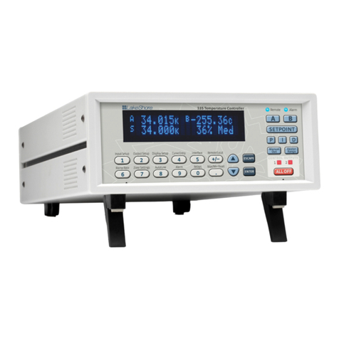
Model 335 front view
1.1 Product
Description
Features:
DOperates down to 300 mK with appropriate NTC RTD sensors
DTwo sensor inputs
DTwo configurable PID control loops providing 50 W and 25 W or 75 W and 1 W
DAutotuning automatically calculates PID parameters
DAutomatically switch sensor inputs using zones to allow continuous measure-
ment and control from 300 mK to 1505 K
DCustom display setup allows you to label each sensor input
DUSB and IEEE-488 interfaces
DSupports diode, RTD, and thermocouple temperature sensors
DSensor excitation current reversal eliminates thermal EMF errors for
resistance sensors
D±10 V analog voltage outputs, alarms, and relays
Designed with the user and ease of use in mind, the Model 335 temperature control-
ler offers many user-configurable features and advanced functions that until now
have been reserved for more expensive, high-end temperature controllers. The
Model 335 is the first two-channel temperature controller available with user
configurable heater outputs delivering a total of 75 W of low noise heater power:
50 W and 25 W, or 75 W and 1 W. With that much heater power packed into an afford-
able half-rack sized instrument, the Model 335 gives you more power and control
than ever.
Control outputs are equipped with both hardware and software features allowing
you, and not your temperature controller, to easily control your experiments. Output
one functions as a current output while output two can be configured in either cur-
rent or voltage mode. With output two in voltage mode, it functions as a ±10 V analog
output while still providing 1 W of heater power and full closed loop proportional-
integral-derivative (PID) control capability. Alarms and relays are included to help
automate secondary control functions. The improved autotuning feature of the
Model 335 can be used to automatically calculate PID control parameters, so you
spend less time tuning your controller and more time conducting experiments.
FIGURE 1-1

2cHAPTER 1: Introduction
Model 335 Temperature Controller
The Model 335 supports the industry’s most advanced line of cryogenic temperature
sensors as manufactured by Lake Shore, including diodes, resistance temperature
detectors (RTDs), and thermocouples. The controller’s zone tuning feature allows you
to measure and control temperatures seamlessly from 300 mK to over 1,500 K. This
feature automatically switches temperature sensor inputs when your temperature
range goes beyond the useable range of a given sensor. You’ll never again have to be
concerned with temperature sensor over or under errors and measurement
continuity issues.
The intuitive front panel layout and keypad logic, bright vacuum fluorescent display,
and LED indicators enhance the user-friendly front panel interface of the Model 335.
Four standard display modes are offered to accommodate different instrument con-
figurations and user preferences. Say goodbye to sticky notes and hand written labels,
as the ability to custom label sensor inputs eliminates the guesswork in remembering
or determining the location to which a sensor input is associated. These features,
combined with USB and IEEE-488 interfaces and intuitive menu structure and logic
supports efficiency and ease of use.
As a replacement to our popular Model 331 and 332 temperature controllers, the
Model 335 offers software emulation modes for literal drop-in compatibility. The
commands you are accustomed to sending to the Model 331 and 332 will either be
interpreted directly or translated to the most appropriate Model 335 setting. The
Model 335 comes standard-equipped with all of the functionality of the controllers it
replaces, but offers additional features that save you time and money. With the
Model 335, you get a temperature controller you control from the world leader in
cryogenic thermometry.
1.1.1 Sensor Inputs The Model 335 offers two standard sensor inputs that are compatible with diode and
RTD temperature sensors. The field-installable Model 3060 option adds thermocou-
ple functionality to both inputs.
Sensor inputs feature a high-resolution 24-bit analog-to-digital converter and each
of the two powered outputs function as separate current sources. Both sensor inputs
are optically isolated from other circuits to reduce noise and to deliver repeatable
sensor measurements. Current reversal eliminates thermal electromagnetic field
(EMF) errors in resistance sensors. Ten excitation currents facilitate temperature
measurement and control down to 300 mK using appropriate negative temperature
coefficient (NTC) RTDs. Autorange mode automatically scales excitation current in
NTC RTDs to reduce self heating at low temperatures as sensor resistance changes by
many orders of magnitude. Temperatures down to 1.4 K can be measured and con-
trolled using silicon or GaAlAs diodes. Software selects the appropriate excitation cur-
rent and signal gain levels when the sensor type is entered via the instrument front
panel. To increase your productivity, the unique zone setting feature automatically
switches sensor inputs, enabling you to measure temperatures from 300 mK to over
1,500 K without interrupting your experiment.
The Model 335 includes standard temperature sensor response curves for silicon
diodes, platinum RTDs, ruthenium oxide RTDs, and thermocouples. Non-volatile
memory can also store up to 39 200-point CalCurves for Lake Shore calibrated tem-
perature sensors or user curves. A built-in SoftCal algorithm can be used to generate
curves for silicon diodes and platinum RTDs that can be stored as user curves. Tem-
perature sensor calibration data can be easily loaded into the Model 335 tempera-
ture controller and manipulated using the Lake Shore curve handler software
program.

1.1.2 TemperatureControl 3
|www.lakeshore.com
1.1.2 Temperature
Control
Providing a total of 75 W of heater power, the Model 335 is the most powerful half
rack temperature controller available. Designed to deliver very clean heater power,
precise temperature control is ensured throughout your full scale temperature range
for excellent measurement reliability, efficiency and throughput. Two independent
PID control outputs can be configured to supply 50 W and 25 W or 75 W and 1 W of
heater power. Precise control output is calculated based on your temperature set-
point and feedback from the control sensor. Wide tuning parameters accommodate
most cryogenic cooling systems and many high-temperature ovens commonly used
in laboratories. PID values can be manually set for fine control or the improved auto-
tuning feature can automate the tuning process.
The Model 335 autotuning method calculates PID parameters and provides feedback
to help build zone tables. The setpoint ramp feature provides smooth, continuous set-
point changes and predictable approaches to setpoint without the worry of over-
shoot or excessive settling times. The instrument’s zone tuning feature automatically
switches temperature sensor inputs when your temperature range goes beyond the
useable range of a given sensor. This feature combined with the instrument’s ability
to scale the sensor excitation through ten pre-loaded current settings allows the
Model 335 to provide continuous measurement and control from 300 mK to 1505 K.
Both control outputs are variable DC current sources referenced to chassis ground. As
a factory default, Outputs 1 and 2 provide 50 W and 25 W of continuous power
respectively, both to a 50 )or 25 )load. For increased functionality, Output 2 can
also be set to voltage mode. When set to voltage mode, it functions as a ±10 V analog
output while still providing 1 W of heater power and full closed loop PID control capa-
bility. While in this mode, output 1 can provide up to 75 W of heater power to a
25)load.
Temperature limit settings for inputs are provided as a safeguard against system
damage. Each input is assigned a temperature limit, and if any input exceeds that
limit, both control channels are automatically disabled.
1.1.3 Interface The Model 335 is standard equipped with universal serial bus (USB) and parallel
(IEEE-488) interfaces. In addition to gathering data, nearly every function of the
instrument can be controlled via computer interface. You can download the
Lake Shore curve handler software program to your computer to easily enter and
manipulate sensor calibration curves for storage in the instrument’s non-volatile
memory.
The USB interface emulates an RS-232C serial port at a fixed 57,600 baud rate, but
with the physical plug-ins of a USB. It also allows you to download firmware
upgrades, ensuring the most current firmware version is loaded into your instrument
without having to physically change your instrument.
Both sensor inputs are equipped with a high and low alarm which offers latching and
non-latching operation. The two relays can be used in conjunction with the alarms to
alert you of a fault condition and perform simple on-off control. Relays can be
assigned to any alarm or operated manually.
The ±10 V analog voltage output can be configured to send a voltage proportional to
temperature to a strip chart recorder or data acquisition system. You may select the
scale and data sent to the output, including temperature or sensor units.

Model 335 rear panel
b Sensor input connectors
c Terminal block
(analog outputs and relays)
d USB interface
e IEEE-488 interface
f Line input assembly
g Output 1 heater
h Output 2 heater
i Thermocouple
option inputs
4cHAPTER 1: Introduction
Model 335 Temperature Controller
1.1.4 Configurable
Display
The Model 335 offers a bright, vacuum fluorescent display that simultaneously dis-
plays up to four readings. You can display both control loops, or if you need to monitor
just one input, you can display just that one in greater detail. Or you can custom con-
figure each display location to suit your experiment. Data from any input can be
assigned to any of the locations, and your choice of temperature sensor units can be
displayed. For added convenience, you can also custom label each senor input, elimi-
nating the guesswork in remembering or determining the location to which a sensor
input is associated.
DTwo Input/Output Display with Labels: Standard display option featuring two
inputs and associated outputs.
DCustom Display with Labels: Reading locations can be user configured to accom-
modate application needs. Here, the input names are shown above the measure-
ment readings along with the designated input letters.
DIntuitive Menu Structure: Logical navigation allows you to spend more time on
research and less time on setup.
Displays showing two input/output display with labels, custom display with labels and the intuitive menu structure
1.1.5 Model 3060
Thermocouple Input
Option
The field installable Model 3060 thermocouple input option adds thermocouple
functionality to both inputs. While the option can be easily removed, this is not neces-
sary as the standard inputs remain fully functional when they are not being used to
measure thermocouple temperature sensors. Calibration for the option is stored on
the card so it can be installed in the field and used with multiple Model 335 tempera-
ture controllers without recalibration.
FIGURE 1-2
FIGURE 1-3

1. 2 S e n s o r Se l ec t i o n 5
|www.lakeshore.com
1.2 Sensor
Selection
Silicon diodes are the best choice for general cryogenic use from 1.4 K to above room
temperature. Diodes are economical to use because they follow a standard curve and
are interchangeable in many applications. They are not suitable for use in ionizing
radiation or magnetic fields.
Cernox™ thin-film RTDs offer high sensitivity and low magnetic field-induced errors
over the 0.3 K to 420 K temperature range. Cernox sensors require calibration.
Platinum RTDs offer high uniform sensitivity from 30 K to over 800 K. With excellent
reproducibility, they are useful as thermometry standards. They follow a standard
curveabove 70 K and are interchangeable in many applications.
Sensor temperature range
Model Useful range Magnetic field use
Diodes Silicon Diode DT-670-SD 1.4 K to 500 K T#60 K & B "3 T
Silicon Diode DT-670E-BR 30 K to 500 K T#60 K & B "3 T
Silicon Diode DT-414 1.4 K to 375 K T #60 K & B "3 T
Silicon Diode DT-421 1.4 K to 325 K T #60 K & B "3 T
Silicon Diode DT-470-SD 1.4 K to 500 K T #60 K & B "3 T
Silicon Diode DT-471-SD 10 K to 500 K T #60 K & B "3 T
GaAlAs Diode TG-120-P 1.4 K to 325 K T > 4.2 K & B "5 T
GaAlAs Diode TG-120-PL 1.4 K to 325 K T > 4.2 K & B "5 T
GaAlAs Diode TG-120-SD 1.4 K to 500 K T > 4.2 K & B "5 T
Positive Tempera-
ture Coefficient RTDs
100 )Platinum PT-102/3 14 K to 873 K T > 40 K & B "2.5 T
100 )Platinum PT-111 14 K to 673 K T > 40 K & B "2.5 T
Rhodium-Iron RF-800-4 1.4 K to 500 K T > 77 K & B "8 T
Rhodium-Iron RF-100T/U 1.4 K to 325 K T > 77 K & B "8 T
Negative
Temperature
Coefficient RTDs
Cernox™ CX-1010 0.3 K to 325 K1T > 2 K & B "19 T
Cernox™ CX-1030-HT 0.3 K to 420 K1, 3 T > 2 K & B "19 T
Cernox™ CX-1050-HT 1.4 K to 420 K1T > 2 K & B "19 T
Cernox™ CX-1070-HT 4 K to 420 K1T > 2 K & B "19 T
Cernox™ CX-1080-HT 20 K to 420 K1T > 2 K & B "19 T
Germanium GR-300-AA 0.35 K to 100 K3Not recommended
Germanium GR-1400-AA 1.8 K to 100 K3Not recommended
Carbon-Glass CGR-1-500 1.4 K to 325 K T > 2 K & B "19 T
Carbon-Glass CGR-1-1000 1.7 K to 325 K2T > 2 K & B "19 T
Carbon-Glass CGR-1-2000 2 K to 325 K2T > 2 K & B "19 T
Rox™ RX-102 0.3 K to 40 K3T > 2 K & B "10 T
Rox™ RX-103 1.4 K to 40 K T > 2 K & B "10 T
Rox™ RX-202 0.3 K to 40 K3T > 2 K & B "10 T
Thermocouples
3060
Type K 9006-006 3.2 K to 1505 K Not recommended
Type E 9006-004 3.2 K to 934 K Not recommended
Chromel-AuFe 0.07% 9006-002 1.2 K to 610 K Not recommended
1Non-HT version maximum temperature: 325 K
2Low temperature limited by input resistance range
3Low temperature specified with self-heating error: "5 mK
TABLE 1-1

Typical sensor performance
Example
Lake Shore
Sensor
Temperature
Nominal
Resistance/
Voltage
Typical
Sensor
Sensitivity4
Measurement
Resolution:
Temperature
Equivalents
Electronic
Accuracy:
Temperature
Equivalents
Temperature
Accuracy
including
Electronic
Accuracy,
CalCurve and
Calibrated Sensor
Electronic
Control
Stability5:
Temperature
Equivalents
Silicon Diode
DT-670-CO-13
with 1.4H
calibration
1.4 K
77 K
300 K
500 K
1.664 V
1.028 V
0.5597 V
0.0907 V
-12.49 mV/K
-1.73 mV/K
-2.3 mV/K
-2.12 mV/K
0.8 mK
5.8 mK
4.4 mK
4.7 mK
±13 mK
±76 mK
±47 mK
±40 mK
±25 mK
±98 mK
±79 mK
±90 mK
±1.6 mK
±11.6 mK
±8.8 mK
±9.4 mK
Silicon Diode
DT-470-SD-13
with 1.4H
calibration
1.4 K
77 K
300 K
475 K
1.6981 V
1.0203 V
0.5189 V
0.0906 V
-13.1 mV/K
-1.92 mV/K
-2.4 mV/K
-2.22 mV/K
0.8 mK
5.2 mK
4.2 mK
4.5 mK
±13 mK
±69 mK
±45 mK
±38 mK
±25 mK
±91 mK
±77 mK
±88 mK
±1.6 mK
±10.4 mK
±8.4 mK
±9 mK
GaAlAs Diode
TG-120-SD
with 1.4H
calibration
1.4 K
77 K
300 K
475 K
5.391 V
1.422 V
0.8978 V
0.3778 V
-97.5 mV/K
-1.24 mV/K
-2.85 mV/K
-3.15 mV/K
0.2 mK
16 mK
7 mK
6.4 mK
±7 mK
±180 mK
±60 mK
±38 mK
±19 mK
±202 mK
±92 mK
±88 mK
±0.4 mK
±32 mK
±14 mK
±13 mK
100 )Platinum RTD
500 )Full Scale
PT-103 with 14J
calibration
30 K
77 K
300 K
500 K
3.660 )
20.38 )
110.35 )
185.668 )
0.191 )/K
0.423 )/K
0.387 )/K
0.378 )/K
1.1 mK
0.5 mK
5.2mK
5.3 mK
±13 mK
±10 mK
±39 mK
±60 mK
±23 mK
±22 mK
±62 mK
±106 mK
±2.2 mK
±1.0 mK
±10.4 mK
±10.6 mK
Cernox™
CX-1010-SD
with 0.3L
calibration
0.3 K
0.5 K
4.2 K
300 K
2322.4 )
1248.2 )
277.32 )
30.392 )
-10785 )/K
-2665.2 )/K
-32.209 )/K
-0.0654 )/K
8.5 µK
26 µK
140 µK
23 mK
±0.1 mK
±0.2 mK
±3.8 mK
±339 mK
±3.6 mK
±4.7 mK
±8.8 mK
±414 mK
±17 µK
±52 µK
±280 µK
±46 mK
Cernox™
CX-1050-SD-HT6
with 1.4M
calibration
1.4 K
4.2 K
77 K
420 K
26566 )
3507.2 )
205.67 )
45.03)
-48449 )/K
-1120.8 )/K
-2.4116 )/K
-0.0829 )/K
20 µK
196 µK
1.9 mK
18 mK
±0.3 mK
±2.1 mK
±38 mK
±338 mK
±5.3 mK
±7.1 mK
±54 mK
±403 mK
±40 µK
±392 µK
±3.8 mK
±36 mK
Germanium
GR-300-AA
with 0.3D
calibration
0.35 K
1.4 K
4.2 K
100 K
18225 )
449 )
94 )
2.7 )
-193453 )/K
-581 )/K
-26.6 )/K
-0.024 )/K
4 µK
41 µK
56µK
6.3 mK
±48 µK
±481 µK
±1.8 mK
±152 mK
±4.2 mK
±4.7 mK
±6.8 mK
±175mK
±8 µK
±82 µK
±112 µK
±12.6 mK
Germanium
GR-1400-AA
with 1.4D
calibration
1.8 K
4.2 K
10 K
100 K
15288 )
1689 )
253 )
2.8 )
-26868 )/K
-862 )/K
-62.0 )/K
-0.021 )/K
28 µK
91 µK
73 µK
7.1 mK
±302 µK
±900 µK
±1.8 mK
±177 mK
±4.5 mK
±5.1 mK
±6.8 mK
±200 mK
±56 µK
±182 µK
±146 µK
±14.2 mK
Carbon-Glass
CGR-1-500
with 1.4L
calibration
1.4 K
4.2 K
77 K
300 K
103900 )
584.6 )
14.33 )
8.55 )
-520000 )/K
-422.3 )/K
-0.098 )/K
-0.0094 )/K
13 µK
63 µK
4.6 mK
16 mK
±0.1 mK
±0.8 mK
±108 mK
±760 mK
±4.1 mK
±4.8 mK
±133 mK
±865 mK
±26 µK
±126 µK
±9.2 mK
±32 mK
Rox™
RX-102A-AA
with 0.3B
calibration
0.5 K
1.4 K
4.2 K
40 K
3701 )
2005 )
1370 )
1049 )
-5478 )/K
-667 )/K
-80.3 )/K
-1.06 )/K
41 µK
128µK
902 µK
62 mK
±0.5 mK
±1.4 mK
±8 mK
±500 mK
±5 mK
±6.4 mK
±24 mK
±537 K
±82 µK
±256 µK
±1.8 mK
±124 mK
Thermocouple
50 mV
3060-F
Type K
75 K
300 K
600 K
1505 K
-5862.9 µV
1075.3 µV
13325 µV
49998.3 µV
15.6 µV/K
40.6 µV/K
41.7 µV/K
36.006 µV/K
26 mK
10 mK
10 mK
11 mK
±0.25 K7
±0.038 K7
±0.184 K7
±0.73 K7
Calibration not
available from
Lake Shore
±52 mK
±20 mK
±20 mK
±22 mK
4Typical sensor sensitivities were taken from representative calibrations for the sensor listed
5Control stability of the electronics only, in an ideal thermal system
6Non-HT version maximum temperature: 325 K
7Accuracy specification does not include errors from room temperature compensation
6cHAPTER 1: Introduction
Model 335 Temperature Controller
TABLE 1-2

1. 3 M o d e l 3 35 Specif ic a t i o ns 7
|www.lakeshore.com
1.3 Model 335
Specifications
1.3.1 Input
Specifications
Input specifications
Sensor
temperature
coefficient
Input range Excitation
current
Display
resolution
Measurement
resolution
Electronic
accuracy
(at 25 °C)
Measurement temperature
coefficient
Electronic
stability1
Diode Negative 0 V to 2.5 V 10 µA ±0.05%2,3 100 µV 10 µV ±80 µV ±0.005%
of rdg
(10 µV + 0.0005% of rdg)/°C ±20 µV
0 V to 10 V 10 µA ±0.05%2,3 1 mV 20 µV ±320 µV ±0.01%
of rdg
(20 µV + 0.0005% of rdg)/°C ±40 µV
PTC RTD Positive 0 )to 10 )1 mA41 m)0.2 m)±0.002 )
±0.01% of rdg
(0.01 m)+ 0.001% of rdg)/°C ±0.4 m)
0 )to 30 )1 mA41 m)0.2 m)±0.002 )
±0.01% of rdg
(0.03 m)+ 0.001% of rdg)/°C ±0.4 m)
0 )to 100 )1 mA410 m)2 m)±0.004 )
±0.01% of rdg
(0.1 m)+ 0.001% of rdg)/°C ±4 m)
0 )to 300 )1 mA410 m)2 m)±0.004 )
±0.01% of rdg
(0.3 m)+ 0.001% of rdg)/°C ±4 m)
0 )to 1 k)1 mA4100 m)20 m)±0.04 )
±0.02% of rdg
(1 m)+ 0.001% of rdg)/°C ±40 m)
0 )to 3 k)1 mA4100 m)20 m)±0.04 )
±0.02% of rdg
(3 m)+ 0.001% of rdg)/°C ±40 m)
0 )to 10 k)1 mA41 )200 m)±0.4 )
±0.02% of rdg
(10 m)+ 0.001% of rdg)/°C ±400 m)
NTC RTD
10 mV
Negative 0 )to 10 )1 mA41 m)0.15 m)±0.002)±0.06%
of rdg
(0.01 m)+ 0.001% of rdg)/°C ±0.3 m)
0 )to 30 )300 µA41 m)0.45 m)±0.002 )±0.06%
of rdg
(0.03 m)+ 0.0015% of rdg)/°C ±0.9 m)
0 )to 100 )100 µA410 m)1.5 m)±0.01 )±0.04%
of rdg
(0.1 m)+ 0.001% of rdg)/°C ±3 m)
0 )to 300 )30 µA410 m)4.5 m)±0.01 )±0.04%
of rdg
(0.3 m)+ 0.0015% of rdg)/°C ±9 m)
0 )to 1 k)10 µA4100 m)15 m)+0.002%
of rdg
±0.1 )±0.04%
of rdg
(1 m)+ 0.001% of rdg)/°C ±30 m)±0.004%
of rdg
0 )to 3 k)3 µA4100 m)45 m)+0.002%
of rdg
±0.1 )±0.04%
of rdg
(3 m)+ 0.0015% of rdg)/°C ±90 m)±0.004%
of rdg
0 )to 10 k)1 µA41 )150 m)+0.002%
of rdg
±1.0 )±0.04%
of rdg
(10 m)+ 0.001% of rdg)/°C ±300 m)
±0.004% of rdg
0 )to 30 k)300 nA41 )450 m)+0.002%
of rdg
±2.0 )±0.04%
of rdg
(30 m)+ 0.0015% of rdg)/°C ±900 m)
±0.004% of rdg
0)to 100 k)100 nA410 )1.5)+0.005% of
rdg
±10.0 )±0.04%
of rdg
(100 m)+ 0.002% of rdg)/°C ±3 )±0.01%
of rdg
Thermocouple Positive ±50 mV NA 1 µV 0.4µV ±1 µV ±0.05%
of rdg5
(0.1 µV + 0.001% of rdg)/°C ±0.8µV
1Control stability of the electronics only, in ideal thermal system
2Current source error has negligible effect on measurement accuracy
3Diode input excitation can be set to 1 mA
4Current source error is removed during calibration
5Accuracy specification does not include errors from room temperature compensation
TABLE 1-3

8cHAPTER 1: Introduction
Model 335 Temperature Controller
1.3.2 Sensor Input
Configuration
Sensor input configuration
Diode/RTD Thermocouple
Measurement type 4-lead differential 2-lead differential, room
temperature compensated
Excitation Constant current with
current reversal for RTDs NA
Supported sensors
Diodes: Silicon, GaAlAs
RTDs: 100 ) Platinum, 1000 ) Platinum
Germanium, Carbon-Glass, Cernox™, and Rox™
Most thermocouple types
Standard curves DT-470, DT-670, DT-500-D, DT-500-E1,
PT-100, PT-1000, RX-102A, RX-202A
Type E, Type K, Type T,
AuFe 0.07% vs. Cr, AuFe 0.03% vs. CR
Input connector 6-pin DIN Screw terminals in a ceramic
isothermal block
1.3.3 Thermometry
Number of inputs 2
Input configuration Inputs can be configured from the front panel to accept any of the supported
input types. Thermocouple inputs require an optional input card that can be
installed in the field. Once installed, the thermocouple input can be selected from
the front panel like any other input type.
Isolation Sensor inputs optically isolated from other circuits but not each other
A/D resolution 24-bit
Input accuracy Sensor dependent, refer to Input Specifications table
Measurement resolution Sensor dependent, refer to Input Specifications table
Maximum update rate 10 rdg/s on each input, 5 rdg/s when configured as 100 k)NTC RTD
with reversal on
Autorange Automatically selects appropriate NTC RTD or PTC RTD range
User curves Room for 39 200-point CalCurves™ or user curves
SoftCal™ Improves accuracy of DT-470 diode to ±0.25 K from 30 K to 375 K; improves
accuracy of platinum RTDs to ±0.25 K from 70 K to 325 K; stored as user curves
Math Maximum and minimum
Filter Averages 2 to 64 input readings
1.3.4 Control There are two control outputs.
1.3.4.1 Heater Outputs (Outputs 1 and 2)
Control type Closed loop digital PID with manual heater output or open loop;
warm up mode (Output 2 only)
Update rate 10/s
Tuning Autotune (one loop at a time), PID, PID zones
Control stability Sensor dependent, see Input Specifications table
PID control settings
Proportional (gain) 0 to 1000 with 0.1 setting resolution
Integral (reset) 1 to 1000 (1000/s) with 0.1 setting resolution
Derivative (rate) 1 to 200% with 1% resolution
Manual output 0 to 100% with 0.01% setting resolution
Zone control 10 temperature zones with P, I, D, manual heater out,
heater range, control channel, ramp rate
Setpoint ramping 0.1 K/min to 100 K/min
TABLE 1-4
Table of contents
Other Lake Shore Temperature Controllers manuals

Lake Shore
Lake Shore 321-01 User manual

Lake Shore
Lake Shore 218S User manual

Lake Shore
Lake Shore 335 User manual

Lake Shore
Lake Shore 331S User manual

Lake Shore
Lake Shore 325 User manual

Lake Shore
Lake Shore 332 User manual

Lake Shore
Lake Shore DRC-91 C User manual

Lake Shore
Lake Shore 336 User manual

Lake Shore
Lake Shore 340 User manual

Lake Shore
Lake Shore 350 User manual