LAMAR L 7350 User manual

A
A
ASSEMBLY
SSEMBLY
SSEMBLY I
INSTRUCTIONS
NSTRUCTIONS /
/ O
O
OWNERS
WNERS
WNERS M
MANUAL
ANUAL
SERIAL NO. _____________________________________________ PURCHASE DATE:____________________
IMPORTANT:
:
:
READ ALL ASSEMBLY INSTRUCTIONS AND SAFETY PRECAUTIONS BEFORE USING THIS PRODUCT. REFERENCE ALL
SAFETY GUIDELINES AND WARNING LABELS. RETAIN PRODUCT LITERATURE FOR FUTURE REFERENCE.
SAFETY :PROPERLY WARM UP AND STRETCH BEFORE EXERCISING. IF YOU FEEL PAIN OR DIZZINESS AT ANY TIME WHILE
EXERCISING , STOP IMMEDIATELY AND CONSULT YOUR PHYSICIAN.
Part No. 06057 Revision: ADate: 01/06
L 7350
L 7350 R
RECUMBENT
ECUMBENT B
BIKE
IKE

L 7350
REFERENCE INFORMATION PAGE
AssemblyPrep 2
Assembly Parts Listing 3
ProductExplodedView 4
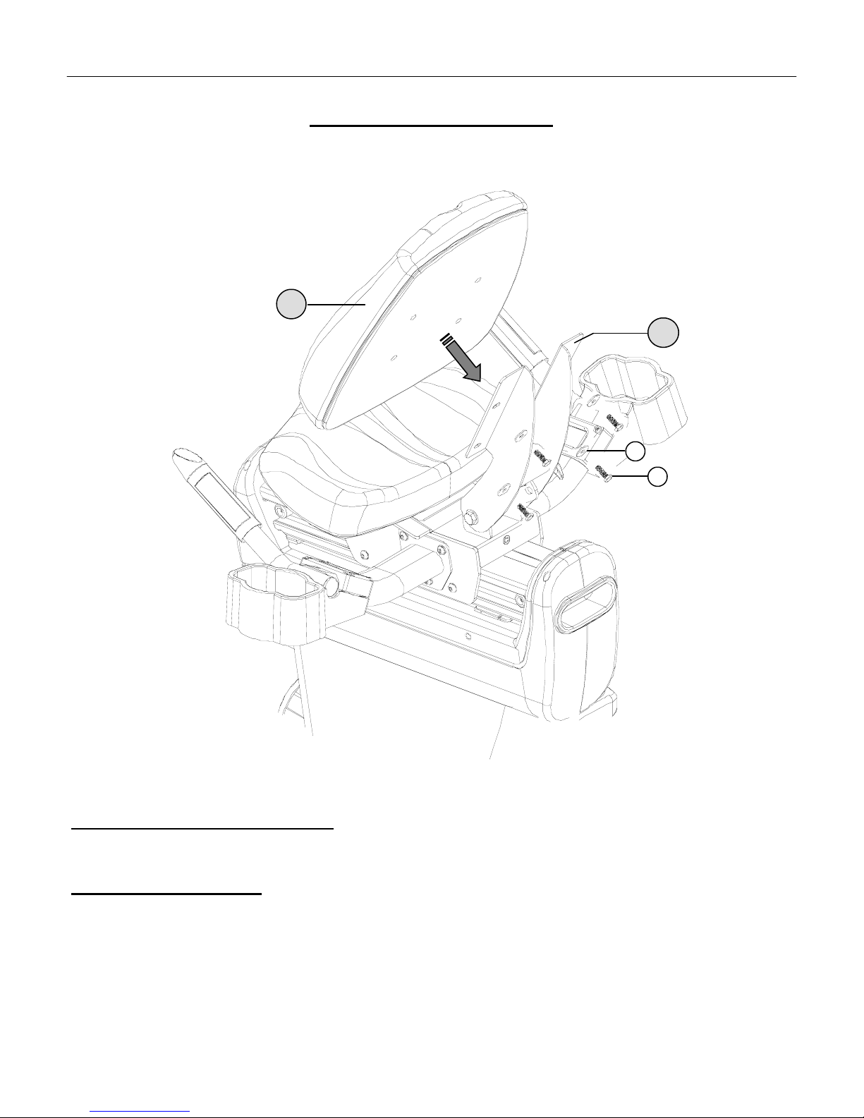
Product Assembly Instruction 5-10
Computer Operation 11-14
Troubleshooting 15
Preventative Maintenance 16
WarrantyTerms 17
ProductRegistration 18
PAGE 1 TABLE OF CONTENTS
I
IMPORTANT
MPORTANT P
PRECAUTIONS
RECAUTIONS
WARNING: To reduce the risk of injury, please read the following precautions before assembling or using your new product.
1. It is the responsibility of the owner to ensure that all users of this equipment are adequately informed of stated precautions.
2. Read all instructions and enclosed literature carefully. Understand the assembly and operation before using the equipment.
3. Use equipment on a flat level surface. Use adjustment levelers on the bottom of equipment to help stabilize unit.
4. It’s recommended to place an exercise / product mat beneath the equipment for added protection of floors or carpets.
5. Keep children & pets away from equipment at all times. Unplug equipment for added safety while not in use.
6. Inspect product on a frequent basis. Tighten loose assemblies or hardware as needed. Replace worn or damaged parts.
7. This equipment is intended for internal home use only. Do not use in a non-residential environment.
8. Use in non-recommended environments can lead to serious injury and will void all related warranties & liabilities.
9. Recommended user weight should not exceed 300 lbs.
10. Frequently wipe equipment down with a dampened soft cloth.
11. Observe and adhere to all warning labels posted on equipment.
12. Properly warm-up and stretch before starting any strength training or cardio exercise routine.
13. If you feel pain or dizziness at any time while exercising, stop immediately and consult your physician.
Safety Warning: Before starting an exercise program, consult your physician. This is especially important for individuals over the age
of 35 or persons with pre-existing health problems. It’s important to read all instructions carefully. We assume no responsibility for
personal injury or consequential damages sustained by or through the use of this equipment. Additional terms & conditions are listed in
the back of this manual or enclosed owners manual.

ASSEMBLY PREPARATION / INTRO PAGE 2
A
ASSEMBLY
SSEMBLY P
PREPARATION
REPARATION
♦ To ensure ease of product assembly, please take time to verify the sizeand quantities of all required assembly
hardware. Use the itemized parts listing for reference.
♦ The product assembly process hasbeen documented in easy tofollow stages. Please read all assembly
instructions carefully. Take time to reviewthe manual and familiarize yourself with the entire assembly
processbefore proceeding.
AssemblyTip: It is always helpful to pre-stage the items needed for each assembly step.
♦ Perform product assembly in a 4ft. x 6ft. flat area.Note: After assembly is completed, allow a minimal of 2-3ft.
of space on each side ofbike for user access.
♦ Do not dispose of any packaging materials until assembly of the product is completed.
♦ Assembly tools are included,but you may also use standard (similar) household tools to complete assemblyof
thisproduct.
♦ If you experience problems with operation of the equipment after assembly, pleasereference the
troubleshootingguide in the back this manual.
♦ For added component life, follow the preventative maintenance tips listed in this manual.
♦ Make sure to completely fill-out the product registration form & return it tous within 30-days of purchase.
♦ Please contact us if youhave additional questions or need service assistance (877-861-2181)
♦ THANK YOU for purchasing aquality LAMAR product.

PARTS REFERENCE
PAGE 3
L 7350
L 7350 PARTS LISTING
ITEM # PART NUMBER DESCRIPTION QTY.
1 NA MAIN BASE ASSEMBLY 1
2 23139 FRONT STABILIZER ASSEMBLY 1
3 05195 END CAPS 1
4 23135 REAR STABILIZER ASSEMBLY 1
5 05189 LEFT PEDAL 1
6 05190 RIGHT PEDAL 1
7 13117 LEFT HANDLE ASSEMBLY 1
8 13118 RIGHT HANDLE ASSEMBLY 1
9 31012 TRAY CLAMP 2
10 31011 BOTTLE TRAY 2
11 NA SEAT SLIDER ASSEMBLY 1
12 03066 SEAT PAD 1
13 13123 BACK PAD SUPPORT 1
14 03065 BACK PAD 1
15 05196 BOOT COVER 1
16 23134 MAST 1
17 10026 COMPUTER 1
18 12072 10-PIN DATA CABLE ASSEMBLY 1
19 12073 5-PIN HR CABLE ASSEMBLY 1
20 13129 SEAT SPACERS (WEDGES) 4
21 01442 HEX SCREW M8 X1.25 X55 LENGTH 4
22 01401 CAP SCREWS M8 X1.25 X15 LENGTH 14
23 01406 HEX SCREW M8 X1.25 X25 LENGTH 4
24 01434 CAP SCREW M8 X1.25 X25 LENGTH 8
25 01414 PHILLIPS SCREW M6 X1.0 X35 LENGTH 4
26 01413 PHILLIPS TRUSS SCREW M5 X.8 X10 LENGTH 4
27 01429 FLAT WASHER 16 X8 X2.0T14
28 01431 FLAT WASHER 25 X8 X2.0T8
29 01426 CURVED WASHER 19 X8.5 X1.5T4
30 01393 LEVELER 3
Note: All assembly hardware is referenced in metric measurements. Screws / bolts are measured by diameter, thread pitch, and
length. Washers are measured by outside diameter, inside diameter, and thickness.
Conversion Reference: 25 millimeters =1.0 inch.

EXPLODED VIEW PAGE 4
11
14
15
1
10
13
7
16
2
3
4
28
30
21
25
27
27
24
22
L 7350
L 7350
C
CUSTOMER
USTOMER S
SERVICE
ERVICE
1
1-
-877
877-
-861
861-
-2181
2181
22
1918 12
9
5
26
8
17
29
NOTE: Most of the listed assembly hardware has been packaged separately, but some hardware items have been
preinstalled in the identified assembly parts. In these instances, simply remove and reinstall the hardware as assembly
is required. Please reference the individual assembly steps and make note of all preinstalled hardware.
22
6
28
23
20
27
27
24

PAGE 5
HEX (JAM) NUT
ASSEMBLY STAGE #1
Attach StabilizerAssemblies
Assembly Hardware Required:
#24 Cap Screws Qty. 8 #27 Flat Washers Qty. 8
Assembly Description:
A) Securely fasten the Front Stabilizer Assembly (#2) to the Base Assembly (#1) using 4-Cap Screws (#24) and
4–Flat Washers (#27). One set of hardware will mount from the top and the other set will mount from the inside
frame flange. Assembly Note: The transport wheels should be facing outward..
B) From the side; tip the unit up a slight angle and slide an End Cap (#3) over each end of the Front Stabilizer
Assembly (#2).
C) Securely fasten the Rear Stabilizer Assembly (#4) to the back of the Base Assembly (#1) using 4- Cap Screws
(#24), 2–Flat Washers (#27). One set of hardware will mount from the top and the other set will mount from the
inside frame flange.
Important: Adjust the Levelers (#30) on bottom the Rear Stabilizer Assembly (#3) and the underside of the middle
frame area to keep the bike from rocking on an uneven surface. Once the correct adjustment is made, tighten the Hex
(Jam) Nuts flush against the frame surface. (Reference FIGURE 1).
♦ Assembly Stage #1 completed
ASSEMBLY INSTRUCTION
24
24 27 4
1
#30 LEVELER
2
FIGURE #1
TRANSPORT WHEELS FACE OUTWARD
3
27
MOVE THE BACK PAD SUPPORT TO AVERTICAL POSITION AND USE THE
T-HANDLE POP-PIN TO LOCK IT IN PLACE.
T-HANDLE POP-PIN

PAGE 6
ASSEMBLY STAGE #2
Attach Pedals
Assembly Hardware Required: (NONE REQUIRED)
Assembly Description:
Important Assembly Note: The right and left pedals are appropriately marked (R) and (L). The threading orientation on
the left pedal is reversed from the threading orientation on the right pedal. To avoid stripping of the threads on the pedals
or crank arms make sure to follow the assembly orientation noted below.
A) Assemble the Left Pedal (#5) to the Left Crank Arm on the Base Assembly (#1). Thread the pedal onto the crank
arm (counterclockwise) and securely tighten in place using the pedal wrench. Note: A counterclockwise rotation will
tighten the pedal to the crank arm and a clockwise rotation will loosen the pedal.
B) Assemble the Right Pedal (#6) to the Right Crank Arm on the Base Assembly (#1). Thread the pedal on the crank
arm and securely tighten in place using the pedal wrench. Note: A clockwise rotation will tighten the pedal to the
crank arm and a counterclockwise rotation will loosen the pedal.
C) Attach the Pedal Straps (included with pedals) to each of the pedals. The straps are labeled (R) or (L) to correspond
with the right and left pedal.
♦ Assembly Stage #2 completed
ASSEMBLY INSTRUCTION
5
6
L
R
FOLLOW ASSEMBLY INSTRUCTIONS CAREFULLY TO AVOID STRIPPING PEDAL THREADS

ASSEMBLY STAGE #3
Attach Handle Assemblies
Assembly Hardware Required:
#22 Cap Screws Qty. 6 #27 Flat Washers Qty. 6
#25 Phillips Screws Qty. 8
Assembly Description:
A) Plug the connectors coming from the Seat Slider Assembly into the corresponding cable receptacles of the Right
Handle Assembly (#8) (Reference FIGURE #2 ). Tuck away the excess cable length and mount the Handle
Assembly to the Seat Slider frame using 3-Cap Screws (#22) and 3-Flat Washers (#27).
B) Plug the connectors coming from the Seat Slider Assembly into the corresponding cable receptacles of the Left
Handle Assembly (#7) (Reference FIGURE #2 ). Tuck away the excess cable length and mount the Handle
Assembly to the Seat Slider frame using 3-Cap Screws (#22) and 3-Flat Washers (#27).
C) Fit the 1-Bottle Tray (#10) and 1-Mounting Clamp (#9) on each handle assembly and secure the parts together
using 4-Phillips Head Screws (#25).
Note: Use the handle / lever (not shown) positioned on the right side of the Seat Slider Assembly to adjust the seat frame
position. Pulling up on the lever, releases the locking mechanism. Once an adjustment is made, release the handle and the
seat frame will lock into a set position.
♦ Assembly Stage #3 completed
ASSEMBLY INSTRUCTIONPAGE 7
FIGURE #2
22 27
9
7
10
8
25

PAGE 8
ASSEMBLY STAGE #4
Attach Seat Pad & (Optional) Spacers
Assembly Hardware Required:
#21 Hex Head Bolts Qty. 4 #28 Flat Washer Qt
y
. 4
Assembly Description:
A) Secure the Seat Pad (#12) and the (optional) 4-Seat Spacers (#20) to the Seat Slider Assembly using 4-Hex
Head Bolts (#21) and 4-Flat Washers (#28).
Seat Spacer Placement: The 4–Seat Spacers (#20) can be used to change the comfort angle of the seat pad. All the
spacers must be used; they can be oriented as shown or rotated 180 degrees to change the angle of the seat pad.
♦ Assembly Stage #4 completed
ASSEMBLY INSTRUCTION
20
21
28
12

PAGE 9
ASSEMBLY STAGE #5
Attach Back Pad
Assembly Hardware Required:
#23 Hex Head Bolts Qty. 4 #28 Flat Washer Qt
y
. 4
Assembly Description:
A) Secure the Back Pad (#14) to the Back Pad Support (#13) using 4-Cap Screws (#23) and 4-Flat Washers (#28).
♦ Assembly Stage #5 completed
ASSEMBLY INSTRUCTION
13
28
23
14

ASSEMBLY INSTRUCTION PAGE 10
ASSEMBLY STAGE #6
Attach Mast & Mount Computer (Final Assembly Step)
Assembly Hardware Required: (*HARDWARE IS PREINSTALLED IN THE BACK OF THE COMPUTER)
#22 Cap Screw Qty. 4 #29 CurvedWasher Qty. 4
#26 *Truss Screw Qty. 4
Assembly Description:
A) Remove the preinstalled mounting hardware (Truss Screws #26) from the back of the computer
B) Slide the Boot Cover (#15) over the lower end of the Mast (#16) and position it out of the way of the hardware
mounting area. (Use a piece of tape to temporarily keep the Boot Cover out of the way).
C) Route the cable assemblies up through middle of the Mast. Position the Mast down onto the Base Assembly and be
careful not to pinch the cables. Secure the Mast to the Base Assembly using 4-Cap Screws (#22) and 4-Curved
Washers (#29). Slide the Boot Cover down over the mounting hardware area.
D) Plug the 10-pin connector of Data Cable(#18) into the matching receptacle on the back of the computer.
E) Plug the 5-pin connector of the Heart Rate Cable (#19) into the matching receptacle in the back of the computer.
F) Tuck excess cable lengths down into the Mast (#16). Place the Computer (#17) on top of the mounting plate and
align the mounting holes with the threaded inserts on the back of the computer. Secure the Computer (#17) to the
mounting plate using the 4-(previously installed) Truss Screws (#26).
C
CONGRATULATIONS
ONGRATULATIONS!
!
You have completed the assembly of this productand you are ready to start exercising toward a healthier lifestyle!
29
5-PIN HR CABLE ASSEMBLY
19
18 10-PIN DATA CABLE ASSEMBLY
16
15
1
17
22
26
# 26 TRUSS SCREWS ARE PREINSTALLED IN THE BACK OF THE COMPUTER

C
COMPUTER
OMPUTER I
INSTRUCTION
NSTRUCTION
BUTTON FUNCTIONS & FEATURES
NOTE: THESE ARE THE BASIC OPERATING FUNCTIONS OF EACH BUTTON. ACTUAL PROGRAMMING FUNCTIONS MAY
REQUIRE AN ACTIVATION SEQUENCE OF MORE THAN ONE BUTTON (REFERENCE : COMPUTER PROGRAMMING ).
[A] RESULTS PAUSES THE COMPUTER AND ALLOWS THE USER TO REFERENCE ALL FUNCTION TOTALS
(ACCUMULATED TIME, DISTANCE, CALORIES AND WATTS). OPTIONAL GRIP CONTROL
[B] RECOVERY ACTIVATES FITNESS TRAINING EVALUATION (USER FITNESS GAUGE). OPTIONAL GRIP CONTROL
[C] QUICK START ALLOWS A USER TO SKIP ALL PROGRAMMING SETUP AND START IMMEDIATE TRAINING IN THE
MANUAL MODE.
[D] START / STOP ACTIVATES & STOPS COMPUTER FUNCTIONS
[E] DOWN SELECTS PROGRAM MODE & ADJUST (DECREASES) DISPLAY SETTINGS. OPTIONAL GRIP CONTROL
[F] UP SELECTS PROGRAM MODE & ADJUST (INCREASES) DISPLAY SETTINGS. OPTIONAL GRIP CONTROL
[G] ENTER SELECTS, SETS, AND ACTIVATES DISPLAY FUNCTIONS.
[H] RESET RESETS PROGRAMMING OPTIONS AND CLEARS DISPLAY VALUES TO ZERO. HOLDING THE
BUTTON DOWN FOR AT LEAST 3 SECONDS WILL CLEAR ALL DISPLAY VALUES, INCLUDING USER
SET UP VALUES.
[I] BMI ACTIVATES DISPLAY MEASUREMENT (GAUGE) OF A USER’S BODY MASS. NOTE: COMPUTER MUST
BE IN THE STOP MODE IN ORDER TO ACTIVATE BMI READING.
[J] LCD ILLUMINATED DISPLAY REFERENCES TRAINING GRIDS AND FUNCTION READOUTS.
[K] READING RACK PULL OUT FEATURE ALLOWS USER ADDED CONVENIENCE.
SPECIAL FEATURES
SELF - GENERATING POWER TO THE BIKE IS GENERATED BY SELF-CONTAINED POWER SUPPLY, WHICH IS ACTIVATED
POWER SOURCE VIA THE ROTATION OF THE PEDALS. NO EXTERNAL AC POWER SUPPLY IS REQUIRED. NOTE: 4 - AA
BATTERIES MUST BE INSTALLED IN THE BACK OF THE COMPUTER IN ORDER TO PROPERLY USE
SOME OF THE SPECIAL DISPLAY FUNCTIONS.
HANDLE / GRIP RIGHT GRIP CONTROLS ALLOW USER TO ACTIVATE RECOVERY AND RESULTS FUNCTIONS.
CONTROLS LEFT GRIP CONTROLS ALLOW USER TO MAKE UP AND DOWN ADJUSTMENTS.
COMPUTER OPERATIONPAGE 11
C
D
E F
G
H
B
A
I
J
K

DISPLAY FUNCTIONS / READINGS
NOTE: SOME WINDOWS WILL REFERENCE MORE THAN ONE FUNCTION. THE FUNCTIONS WILL ALTERNATE EVERY 6-8 SECONDS.
TIME COMPUTER DISPLAY WILL ACCUMULATE TOTAL TRAINING TIME IN 00:00 (MINUTES : SECONDS). COMPUTER
WILL COUNT UP TO, OR DOWN FROM , A MAXIMUM READING OF 99:00.
PRESET TARGET TRAINING TIME: A PRESET TRAINING TIME CAN ONLY BE SET IN THE MANUAL AND
PROGRAM TRAINING MODES. ONCE A TRAINING MODE IS CHOSEN AND A RESISTANCE LEVEL IS SET, THE
TIME ICON WILL BEGIN FLASHING. (A 20:00 MINUTE PRESET WILL SHOW IN THE TIME WINDOW). USE THE UP /
DOWN BUTTONS TO ADJUST THE SETTING. SETTINGS WILL BE ENTERED IN 1:00 MINUTE INCREMENTS AND THE
COMPUTER WILL COUNT DOWN FROM THE SET TIME (COMPUTER WILL COUNT UP FROM A 00:00 ENTRY) . ONCE
THE DESIRED TIME IS SET, PRESS START / STOP BUTTON TO BEGIN TRAINING. ONCE A SET TRAINING TIME IS
COMPLETED, THE COMPUTER WILL “BEEP” AND ALL READINGS WILL STOP. NOTE: AFTER A PRESET TIME AS
ENDED, A USER CAN PRESS START / STOP TO CONTINUE TRAINING AND THE COMPUTER WILL COUNT UP FROM
00:00.
SPEED THE COMPUTER WILL REGISTER AND DISPLAY TRAINING SPEED (MPH).
RPM THE COMPUTER WILL READ AND DISPLAY PEDAL / DRIVE TRAIN ROTATIONS.
DISTANCE THE COMPUTER ACCUMULATES TRAINING DISTANCE FROM 0.00 TO A MAXIMUM OF 99.99 MILES. EACH
INCREMENT WILL BE DISPLAYED IN 0.01 MILE OR KILOMETER.
CALORIE COMPUTER ACCUMULATES TOTAL CALORIE CONSUMPTION (BURN) DURING A TRAINING PERIOD. COMPUTER
WILL COUNT IN 1 CALORIE INCREMENTS, FROM 0 TO A MAXIMUM READING OF 9990 CALORIES.
NOTE: THE REPORTED CALORIE DATA IS ONLY A REFERENCE GUIDE FOR THE USER. IT SHOULD NOT BE USED
IN COMPARISON OF CALIBRATED MEDICAL EQUIPMENT.
PULSE THE COMPUTER CAN DISPLAY A USER'S HEART RATE READING. A BLINKING HEART SYMBOL & NUMERIC
READING WILL BE DISPLAYED ON THE COMPUTER AS LONG AS A USER’S HANDS ARE LOCATED ON THE GRIP
SENSORS. READINGS WILL APPEAR WITHIN 30 SECONDS TO 1 MINUTE OF CONSISTENT GRIP CONTACT.
READINGS WILL BECOME INCONSISTENT IF A USER FAILS TO LEAVE BOTH HANDS IN CONTACT WITH THE GRIP
SENSORS. (See Target Heart Rate Training)
NOTE: HEART RATE READINGS ARE ONLY A REFERENCE OF A USER’S PULSE RATE DURING TRAINING. THESE
READOUTS SHOULD NOT BE USED IN COMPARISON WITH CALIBRATED MEDICAL EQUIPMENT. SOME USERS
MAY EXPERIENCE INCONSISTENCIES IN READINGS DUE TO THE NATURE OF THEIR PHYSICAL CONDITION.
WATT THE COMPUTER WILL MEASURE A USER’S TRAINING OUTPUT (WORKLOAD). THE COMPUTER WILL
AUTOMATICALLY CONFIGURE AND DISPLAY WATT READINGS DURING ALL TRAINING MODES. READINGS
WILL BE DISPLAYED IN 1-WATT INCREMENTS.
RECOVERY THE COMPUTER WILL ALLOW A USER TO EVALUATE THEIR FITNESS LEVEL AFTER COMPLETING A TRAINING
SESSION. THE EVALUATION IS BASED ON A USER’S HEART RATE RECOVERY. ACTIVATION: AFTER
COMPLETING A TRAINING SESSION; STOP PEDALING, PRESS THE RECOVERY BUTTON, AND PLACE BOTH
HANDS ON THE SENSOR GRIPS. THE COMPUTER WILL AUTOMATICALLY STOP ALL DISPLAY FUNCTIONS
EXCEPT “TIME”, WHICH WILL START COUNTING DOWN FROM 60 SECONDS. ONCE THE COUNT DOWN IS
COMPLETED, THE USER CAN REMOVE THEIR HANDS FROM THE SENSOR GRIPS. THE DISPLAY WILL SHOW A
RATING OF A+ THROUGH C RATING. THE A+ READING IS THE BEST RATING POSSIBLE. USERS CAN MONITOR
THEMSELVES AFTER EACH TRAINING SESSION AND USE THE RECOVERY READING AS A GAUGE FOR CARDIO
CONDITIONING. (BATTERIES MUST BE INSTALLED IN THE BACK OF THE COMPUTER TO USE THIS FUNCTION)
NOTE: PRESS THE RECOVERY BUTTON AGAIN TO RETURN TO THE NORMAL DISPLAY FUNCTIONS.
COMPUTER OPERATION PAGE 12
C
COMPUTER
OMPUTER I
INSTRUCTION
NSTRUCTION

PAGE 13
C
COMPUTER
OMPUTER I
INSTRUCTION
NSTRUCTION
DISPLAY FUNCTIONS (Continued)
BODY MASS BODY MASS INDEX (BMI): CALCULATED NUMBER USED TO DETERMINE HEALTHY WEIGHT RANGES
THE COMPUTER WILL ALLOW A USER TO MEASURE THEIR BODY COMPOSITION BASED ON BODY MASS INDEX
(BMI) EVALUATION. THE READINGS ARE CALCULATED USING A COMBINATION OF USER ENTRY DATA (HEIGHT,
WEIGHT, AGE, & GENDER) AND HEART RATE SAMPLING.
ACTIVATION: THE COMPUTER MUST BE THE STOP MODE IN ORDER TO ACTIVATE BMI FEATURE. AFTER
COMPLETING A TRAINING SESSION, PRESS THE BODYMASS BUTTON AND PLACE THE PALMS OF BOTH HANDS
ON THE HEART RATE GRIP (SENSORS). A FLASHING HEART SYMBOL WILL APPEAR ON DISPLAY AND AFTER
SEVERAL SECONDS A NUMERIC RATING WILL BE DISPLAYED. USE THE CHART BELOW TO EVALUATE BMI
RATING.
BODY MASS INDEX (BMI)
BMI SUMMARY BODY FAT AND BODY MASS MEASUREMENTS ARE RECOGNIZED AS ESSENTIAL FACTORS IN
ACCESSING A PERSONS PHYSICAL CONDITION. HIGHER READINGS ARE FLAGS TO POTENTIAL
WEIGHT RELATED HEALTH RISK. THESE RISK INCLUDE, BUT ARE NOT LIMITED TO; HEART DISEASE,
HIGH BLOOD PRESSURE, DIABETES, AND OSTEOARTHRITIS.
ANOTHER IMPORTANT FACTOR IS THAT MUSCLE TISSUE WEIGHS MORE THAN FAT TISSUE. CERTAIN
TYPES OF EXERCISE WILL BUILD MUSCLE MASS. MUSCLED TONED INDIVIDUALS MAY HAVE A
LOWER BODY FAT PERCENTAGE, BUT REGISTER HIGHER BODY MASS (BMI) READINGS. BASED ON
STANDARD WEIGHT CHARTS THESE INDIVIDUALS MAY BE CONSIDERED OVERWEIGHT, BUT BASED
ON OVERALL BODY COMPOSITION, WOULD BE LABELED AS FIT INDIVIDUALS.
PHYSICAL ACTIVITY AND GOOD NUTRITION ARE KEY FACTORS TO MAINTAINING A HEALTHIER
LIFESTYLE. CONSISTENT CARDIOVASCULAR EXERCISE WILL LEAD TO THE GREATEST METABOLISM
(BURNING) OF FAT. BY KEEPING BODY FAT LEVELS IN AN ACCEPTABLE RANGE, YOU WILL LOOK AND
FEEL BETTER. MAKE SURE TO SET REALISTIC FITNESS GOALS AND DEVELOP A TRAINING REGIMENT
THAT WORKS BEST YOU.
THE READINGS FROM THIS PRODUCT ARE OFFERED AS A POINT OF REFERENCE IN DEVELOPING
TRAINING METHODS WHICH ARE BENEFICIAL TO ACHIEVING FITNESS GOALS. READINGS SHOULD
ONLY BE USED AS A TRAINING GAUGE AND NOT BE CONSIDERED AS A REPLACEMENT FOR
PROFESSIONAL MEDICAL ADVISE. IT IS A IMPORTANT TO NOTE; BODY FAT AND BODY MASS ARE
ONLY PART OF A PERSON’S HEALTH PROFILE. WE RECOMMEND TALKING TO YOUR PERSONAL
PHYSICIAN ABOUT OTHER MEASURES AND ASSOCIATED HEALTH FACTORS.
TARGET HEART RATE (THR) TRAINING
THIS TYPE OF TRAINING IS BASED ON EXERCISING WITHIN A PRESET TARGET VALUE OF A USER’S MAXIMUM
HEART RATE. THE TARGET HEART RATE PROGRAM ALLOWS A USER TO SELECT A CUSTOMIZED SETTING
RANGING FROM 70 - 240. THE BIKE RESISTANCE WILL AUTO-ADJUST BASED ON THE ZONE TARGET AND A
USER’S PULSE READINGS.
SETTING A TARGET HR: 1) USE THE FORMULA (220 BPM - AGE) TO DETERMINE MAXIMUM HEART RATE.
2) ENTER A HR TARGET SETTING (70 –240). NOTE: WE RECOMMEND SETTING A VALUE BASED ON 55% ,
75%, OR 90% OF THE MAXIMUM HR. 3) ONCE AN HR TARGET SETTING IS ENTERED, THE USER CAN SET A
DESIRED TRAINING TIME OR PRESS THE START / STOP BUTTON TO ACTIVATE THE HR TRAINING MODE. NOTE:
IF NO TRAINING TIME IS SET, THE COMPUTER WILL COUNT DOWN FROM A 20 MINUTE DEFAULT SETTING.
TRAINING RESISTANCE: ONCE THE TARGET HR MODE IS ACTIVATED, THE USER MUST KEEP BOTH PALMS ON
THE GRIP SENSORS OF THE HANDLE ASSEMBLY. THE COMPUTER WILL DISPLAY THE USER’S HEART RATE AND
BEEP IF THE USER IS NOT STAYING WITHIN THE PRESET TARGET VALUE. THE TRAINING RESISTANCE WILL
AUTOMATICALLY ADJUST TO KEEP THE USER WITHIN THE DESIRED HR TARGET SETTING. (EXAMPLE: IF A USER
FALLS BELOW THE SET HR TARGET VALUE, THE RESISTANCE WILL GRADUALLY INCREASE EVERY 30
SECONDS UNTIL A USER’S HR READING FALLS WITHIN THE PRESET TARGET VALUE).
COMPUTER OPERATION
UNDERWEIGHT IDEAL WEIGHT OVERWEIGHT HIGH RISK
< 20 20 - 24.9 25 - 29.9 30 >

PAGE 14
C
COMPUTER
OMPUTER P
PROGRAMMING
ROGRAMMING
COMPUTER OPERATION
2
4
4.1
3
1 ACTIVATION
Start pedaling and proceed with set up sequence
SELECT USER ID (U0 - U4)
Use the UP / DOWN buttons to select a USER ID
and press the ENTER button.
ENTER USER PROFILE
1. Use the UP / DOWN buttons to select GENDER and press ENTER.
2. Use the UP / DOWN buttons to select AGE and press ENTER.
3. Use the UP / DOWN buttons to select HEIGHT and press ENTER.
4. Use the UP / DOWN buttons to select WEIGHT and press ENTER.
SELECT TRAINING MODE
1. Press the UP button once to select MANUAL mode and press ENTER to activate.
2. Press the UP button twice to select PROGRAM mode and press ENTER to activate.
3. Press the UP button three times to select TARGET HR mode and press ENTER to activate
4. Press the UP button four times to select TIME TRIAL and press ENTER to activate.
QUICK START FEATURE
Press the QUICK START button to skip all data entry steps
and begin training in the MANUAL mode.
Note: Time will count up from 00:00 setting and a user can
adjust the resistance using the UP / DOWN buttons.
PROGRAM
(1-6) TARGET
HEART RATE
MANUAL
Use the UP / DOWN button to adjust a
TIME setting.
Note: Time will count down from a
20:00 minute preset if no adjustment is
made.
Use the UP / DOWN button to select a
Preprogrammed Training Profile (1-6).
♦Press ENTER to lock in the setting.
Use the UP / DOWN button to adjust a
TIME setting.
Note: Time will count down from a
20:00 minute preset if no adjustment is
made.
Use the UP / DOWN button to select a
HR Target setting from 70 - 240
♦Press ENTER to lock in the setting.
Use the UP button to select a Resistance
Level (1-16). Note: Resistance level can
be readjusted during training .
♦Press ENTER to lock in the setting.
Note: No resistance setting available.
Resistance will automatically adjust
based on the HR Target setting.
♦SEE PAGE 13
Press the START / STOP button
to begin training.
4.2 4.3
Use the UP / DOWN button to adjust a
TIME setting.
Note: Time will count down from a
20:00 minute preset if no adjustment is
made.
Use the UP button to select a Resistance
Level (1-16). Note: Resistance level can
be readjusted during training .
♦Press ENTER to lock in the setting.
Press the START / STOP button
to begin training.
TIME
TRIAL
Press the START / STOP button
to begin training.
4.4
Use the UP / DOWN button to select
5K , 10K , 20K training program.
♦Press ENTER to lock in the setting.
Use the UP button to select a Resistance
Level (1-16)
♦Press ENTER to lock in the setting.
Press the START / STOP button
to begin training.

TROUBLESHOOTING
PAGE 15
T
TROUBLESHOOTING
ROUBLESHOOTING T
TIPS
IPS
PROBLEM DESCRIPTION SUGGESTED SOLUTION
1.NODISPLAY 1.1 (IF APPLICABLE) CHECK THE EXTERNAL AC ADAPTER FOR PROPER
VOLTAGE OUTPUT (9-12 VDC).
1.2 INSPECT PLUG-IN RECEPTACLE ON THE FRONT OF THE UNIT FOR
DAMAGE.
1.3 CHECK CABLE CONNECTIONS: MAKE SURE CONNECTIONS ARE SECURE
AND IN THE CORRECT ORIENTATION.
1.4 CHECK CABLE ASSEMBLIES FOR DAMAGE: PINCH POINTS & POSSIBLE
SHORTING OF WIRES.
1.5 CHECK FOR POSSIBLE COMPUTER DAMAGE: CRACKED DISPLAY
WINDOW (BLACK SCREEN).
* If computer still fails to operate after checking these suggestions, contact us
for technical support.
2. PRODUCT WILL NOTSIT LEVEL 2.1 USE LEVELERS ON THE BOTTOM OF THE REAR STABILIZER AND THE
MIDDLE OF THE MAIN FRAME TO ADJUST EQUIPMENT STABILITY.
3.SEAT MOVEMENT/ADJUSTMENT 3.1 MAKE SURE THE ADJUSTMENT LEVER (LOCATED ON THE RIGHT SIDE OF
THE SEAT FRAME) HAS LOCKED IN DOWNWARD POSITION.
3.2 ADJUSTMENTS: PULLING UP ON THE SEAT LEVER WILL RELEASE THE
LOCKING MECHANISM AND SEAT CAN BE REPOSITIONED.
4. PEDAL WOBBLE 4.1 CHECK TO MAKE SURE PEDALS ARE INSTALLED CORRECTLY
(ORIENTATION) AND MOUNTED FLUSH WITH THE CRANK ARMS.
4.2 LOOSEN THE PEDALS, CHECK FOR POSSIBLE CROSS-THREADING OF
CRANK ARMS.
5. NO SPEED / RPM READING 5.1 CHECK COMPUTER CONNECTION: MAKE SURE ALL THE CONNECTORS
ARE SECURE AND IN THE CORRECT ORIENTATION.
6. ERRATIC HEART RATE 6.1 MAKE SURE PALMS OF HAND ARE CENTERED ON GRIP SENSORS.
6.2 CHECK CABLE CONNECTIONS FROM HANDLE ASSEMBLIES AND THE
BACK OF THE COMPUTER . LOOK FOR PINCHED CABLES IN MAST AREA.
NOTE: A USER'S PHYSICAL CONDITION CAN EFFECT THE ACCURACY OF
A READING, AS WELL AS, UNCONTROLLABLE INTERFERENCES.
Make sure to reference the assembly steps & parts informationin this manual when performing any troubleshooting.
If you experience other technical problems or have additional questions, please contact us at:
C
CUSTOMER
USTOMER S
SERVICE
ERVICE 1
1-
-877
877-
-861
861-
-2181
2181

PREVENTATIVE MAINTENANCE PAGE 16
E
EQUIPMENT
QUIPMENT M
MAINTENANCE
AINTENANCE
♦ Use a dampened soft cloth to wipe equipment free of perspiration after each use. Avoid getting
excessive moisture on computer or electronic components. Do not use abrasive cleaners or
petroleum-based solvents to clean equipment.
♦ Do not remove drive train shrouds or attempt any technical service on equipment without
consulting an authorized service representative.
♦ Regularly inspect product for loose assembly hardware and worn components.
♦ (If applicable) For added safety, unplug equipment from the wall socket when it is not being used.
♦ Use a product /exercise mat underneath equipment for protection of floors & carpets.
♦ (If applicable) Apply recommended component lubricants at the required time periods.
♦ Keep product assembly manual, purchase receipt, and service records in a safe storage place.
♦ ( If applicable) Periodically check batteries for proper voltage output & replace as needed.
♦ Do not store or use equipment outdoors.
♦ Moving equipment:
Recumbent bikes; Unplug the AC Adapter (if applicable) and carefully lift the unit up using
the rear stabilizer. Lift the unit up at an angle until the front transport wheels make contact
with the floor and steer the equipment to the desired location.
T
TRAINING
RAINING
FOR
FOR S
SUCCESS
UCCESS
How you start an exercise program depends on your physical condition. If you have been inactive for
awhile or you have pre-existing health condition, you should start slowly. Initially you may only be
able to exercise for a short amount of time using minimal resistance levels or weight loads.
Begin your desired training program slowly and gradually increase the amount of time you exercise.
Apply realistic goals, that have been set by you or your physician. You should see sufficient gains in
your personal fitness level within 6-8 weeks of continuous exercise,but do not be discouraged if it takes
longer. It is very important to exercise at your own pace and become confident in obtaining your goals.
It is also important to apply warm-up, stretching, and cool down periods with anyexercise program.
As your fitness level increases, so will your confidence and sense of accomplishment. Regular exercise
and a healthy diet will energize you and offer a sense of well-being.

General Terms & Conditions
All LAMAR Health, Fitness & Sports, LLC exercise products are
warranted to be free from defects in materials and workmanship
under the terms of recommended use and warranty coverage.
Warranty coverage is valid to the original retail purchaser and is not
transferable. Coverage will be calculated from the date of retail
purchase. Original proof of purchase and serial number identification
will be required with any associated warranty claim.
Coverage periods & warranty terms may vary per product model.
Applied warranties will be based on type of product, components,
and recommended application (use environment). Products sold or
placed in non-recommended user applications will void all warranty
coverage set forth by LAMAR Health, Fitness & Sports, LLC.
Coverage Periods
LAMAR Health, Fitness & Sports, LLC hereby extends the following
limited warranties for the application, components, and time periods
indicated;
User Environment: Residential ***Light Commercial
Structural Frame: Lifetime (Limited) 15 Years
Mechanical Parts: 3 Years 2 Year
Electronic Parts: 2 Years 1 Year
Wear Items*: 1 Year 6 Months
Labor**: 1 Year 6 Months
*Wear items are those components that may need replacement based
on normal wear & tear conditions (i.e. cables, upholstery, grips, etc.).
**Labor coverage excludes unauthorized repairs, service calls, and
non-warranty related charges.
*** Light Commercial are those environments rated for equipment
use of 20 hours or less a week.
Exclusions & Limitations
Applied warranties are exclusive to LAMAR Health, Fitness &
Sports, LLC. Warranty coverage will not extend to any product not
purchased from LAMAR Health, Fitness & Sports, LLC or from an
authorized reseller.
Warranty coverage is void and will not extend to; a) use of product in
non-recommended environments; b) invalid claims and / or; c) any
damage, failure or loss due to improper assembly / installation,
improper maintenance, negligence, misuse, unauthorized repair,
alteration, accident, normal wear & tear, or an ACT OF GOD.
Except as expressly set forth in the stated warranty terms
LAMAR Health, Fitness & Sports, LLC makes no other
warranties, expressed or implied including, but not limited to,
any implied warranties of merchantability and fitness for a
particular purpose. Any implied warranties that may be imposed
by law are limited to the terms stated within LAMAR Health,
Fitness & Sports, LLC product warranties. Neither LAMAR
Health Fitness & Sports, LLC nor any of its affiliates will be
responsible for incidental or consequential damages. Some states
do not allow limitations on how long an implied warranty lasts or
the exclusion or limitation of incidental or consequential
damages, so the preceding exclusions or limitations may not
apply. The stated warranty gives you specific legal rights and you
may have other rights that vary state to state. LAMAR Health,
Fitness & Sports, LLC neither assumes or authorizes anyone to
assume for it any other express warranty.
Exclusive Remedies
For any product that fails to conform under the terms of applied
warranty, LAMAR Health, Fitness & Sports, LLC will provide, at
their option, one of the following; 1) repair or replacement of
defective parts or; 2) replacement of equipment with a product of
equal value; 3) limited credit reimbursement toward another LAMAR
Health Fitness & Sports product.
Service Procedure
Obtain warranty service by contacting LAMAR Health, Fitness &
Sports, LLC or the original place of product purchase. (If Applicable)
Warranty service will be performed by the original reseller or an
authorized service provider. All warranty claims must be validated
and meet the requirements set forth by LAMAR Health, Fitness &
Sports, LLC. Warranty claims will include confirmation of model
number, serial number, and all pertinent information supporting the
existence of an alleged defect. All non-warranty related service cost
will be the sole responsibility of the purchaser.
Purchaser is responsible for all transportation of product to and from
the reseller. Service calls & travel fees are not covered under standard
warranty labor and are the responsibility of the purchaser.
Unauthorized repairs, service performed by someone other than an
authorized service provider, and / or use of unapproved replacement
parts will void warranty coverage.
Additional service exclusions and limitations may exist based on the
associated distribution agreement under which the product is sold
and / or purchased.
Note to Authorized Warranty Service Providers:
Warranty labor reimbursement or warranty parts rights may not be
transferred or reassigned to a third party service provider without the
authorization of LAMAR Health, Fitness & Sports, LLC.
Product Registration
Fill out the enclosed warranty registration form and return to
LAMAR Health, Fitness & Sports, LLC within 30 days of product
purchase. You can also register your product online. Along with
product registration, keep copies of all product information for your
personal records.
Product Information
Model:_______________________ Purchase Date:_____________
Serial Number:___________________________________________
Contact Information:
Address:
LAMAR H
LAMAR HEALTH
EALTH, F
, FITNESS
ITNESS & S
& SPORTS
PORTS, LLC
, LLC
4699 N
4699 NAUTILUS
AUTILUS C
COURT
OURT S
SOUTH
OUTH #205
#205
B
BOULDER
OULDER, C
, COLORADO
OLORADO 80301
80301
Phone: 877.861.2181
Email: www.lamarhfs.com
LIMITED WARRANTY
PAGE 17

Please Cut Along This Line
Thank you for purchasing a LAMAR Health, Fitness & Sports, LLC product. Our products are designed and manufactured
to the highest quality standards. We are committed to our customers satisfaction and we will do everything we can under the
conditions of your product warranty to keep you secure in your product purchase. To help us serve you better, please fill out
this Product Registration form & return it to us within 30-days of product purchase.
Send completed registration form to: LAMAR H
LAMAR HEALTH
EALTH, F
, FITNESS
ITNESS & S
& SPORTS
PORTS, LLC
, LLC
4699 N
4699 NAUTILUS
AUTILUS C
COURT
OURT S
SOUTH
OUTH #205
#205
B
BOULDER
OULDER, C
, COLORADO
OLORADO 80301.
80301.
Thank you ! We appreciate your response. The information provided on this questionnaire is used exclusively by LAMAR Health, Fitness & Sports,
LLC and will not be distributed to any other individuals or agencies regardless of purpose.
Safety Recommendations: Consult a physician or health professional before starting any type of exercise program. Warm up and stretch before
staring a exercise routine. Inspect your product for proper assembly. Make sure all hardware is tightened appropriately. Check cables and all
moving parts for smooth movement and full range of motion. If you are unsure of proper use of your purchased product, contact a local retailer
or call us for instruction. Equipment is not designed for the use of children or minors. Failure to follow or apply these suggested safety tips may
result in serious injury.
PRODUCT REGISTRATION
______________________________________________________________
Your Name
______________________________________________________________
Address Apt. #
______________________________________________________________
City
______________________________________________________________
State Zip Code
Phone Number: ________________________________________________
Email Address:_________________________________________________
PRODUCT INFORMATION
Model:________________________________________________________
Product Type:__________________________________________________
(Home Gym, Upright Bike, Free Weight etc.)
Serial Number:_________________________________________________
Date of Purchase:_______________________________________________
(Month / Day / Year)
Purchased From:_______________________________________________
(Retailer Name)
Address: ______________________________________________________
SURVEY
A) How did you learn about our products?
1. □Recommendation of personal trainer
2. □Recommendation of retail salesperson
3. □Recommendation of friend / relative
4. □Article in magazine / newspaper
5. □Internet
6. □TV / radio
7. □other:______________________________________________________
B) Please note all factors that influenced your product purchase:
1. □Valued priced 5. □Strength training
2. □Quality / durability 6. □Cardiovascular fitness
3. □Brand name 7. □Weight loss
4. □Design / look / feel 8. □Home fitness convenience
C) Rate the overall in-home assembly of the product:
□Fair □Average □Excellent
D) Rate the satisfaction with the retailer fromwhich you purchased your product:
□Fair □Average □Excellent
E) What other types of exercise equipment do you own?
1. □Treadmill 5. □Upright bike
2. □Stepper 6. □Recumbent bike
3. □Elliptical 7. □Free weights
4. □Home Gym 8. Other:____________________________
F) What product features / functions are most important to you?
1. □Heart rate monitoring 6. □Design / appearance
2. □Multiple user programs 7. □Ease of assembly
3. □Ease of use 8. □Warranty & service
4. □Quality / durability 9. □Brand recognition
5.□Comfort / fit / feel 10. Other:___________________________
G) How many times a week do you exercise?
□1-2 times □3-4 times □4-5 times □6-7 times
H) What is the duration of your workout?
□20-30 minutes □1-2 hours □2 hours or more
I) Age Group:
□18-25 □26-35 □36-45 □46-55 □56-65 □66 & older
J) Gender: □Male □Female
K) Product used by: □Personal □Spouse □Family
L) Do you belong to a health club, gym, wellness center, etc.?
□Yes □No
PAGE 18

STAMP
FOLD LINE
FOLD & TAPE CLOSED OR MAIL REGISTRATION IN ASEPARATE ENVELOPE
www. lamarhfs. com
LAMAR H
LAMAR H
LAMAR HEALTH
EALTH
EALTH, F
, F
, FITNESS
ITNESS
ITNESS, & S
, & S
, & SPORTS
PORTS
PORTS, LLC
, LLC
, LLC
4699 N
4699 N
4699 NAUTILUS
AUTILUS
AUTILUS C
C
COURT
OURT
OURT S
S
SOUTH
OUTH
OUTH #205
#205
#205
B
B
BOULDER
OULDER
OULDER, C
, C
, CO
O
O. 80301
. 80301
. 80301
This manual suits for next models
1
Table of contents
Other LAMAR Exercise Bike manuals