PAGE 7 ASSEMBLY INSTRUCTION
ASSEMBLY STAGE #3
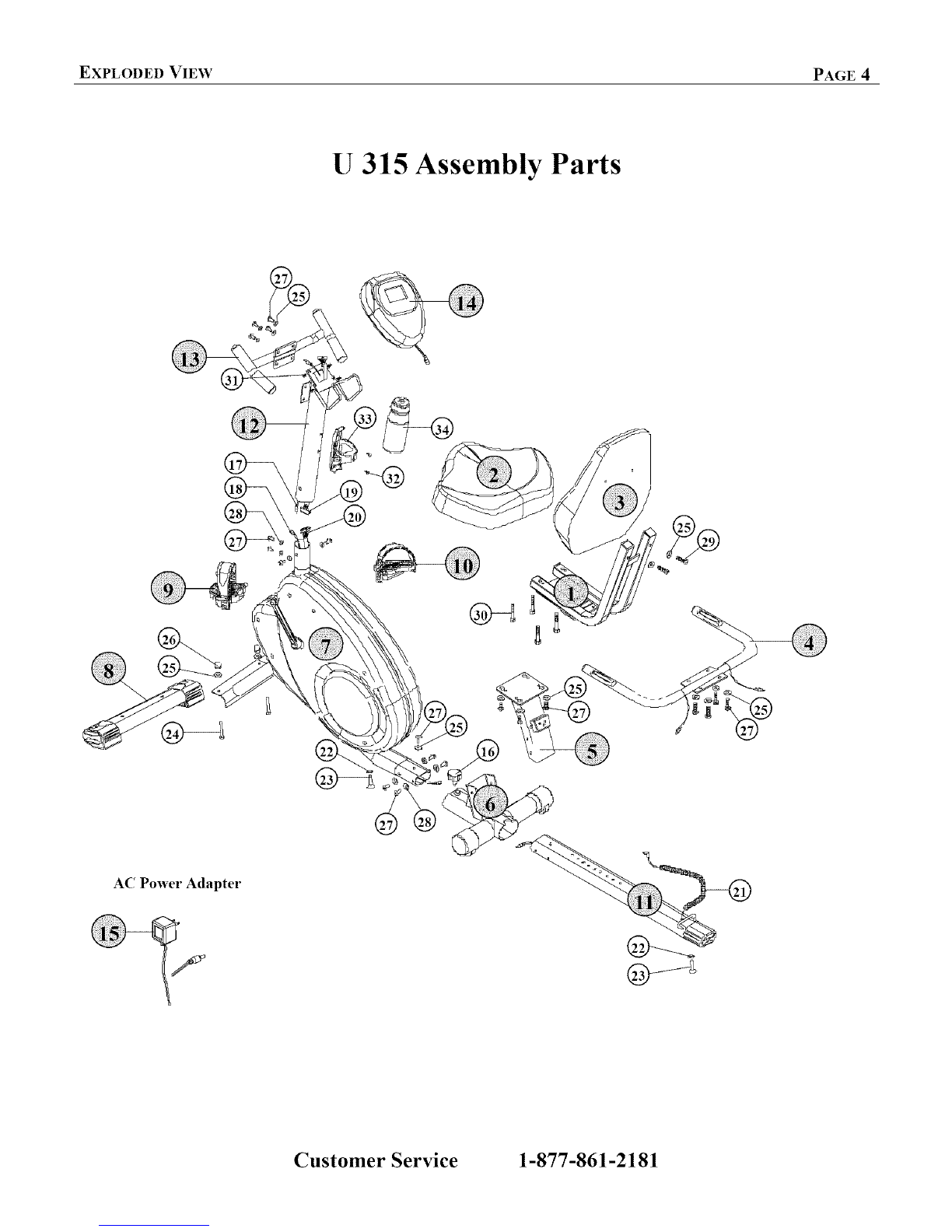
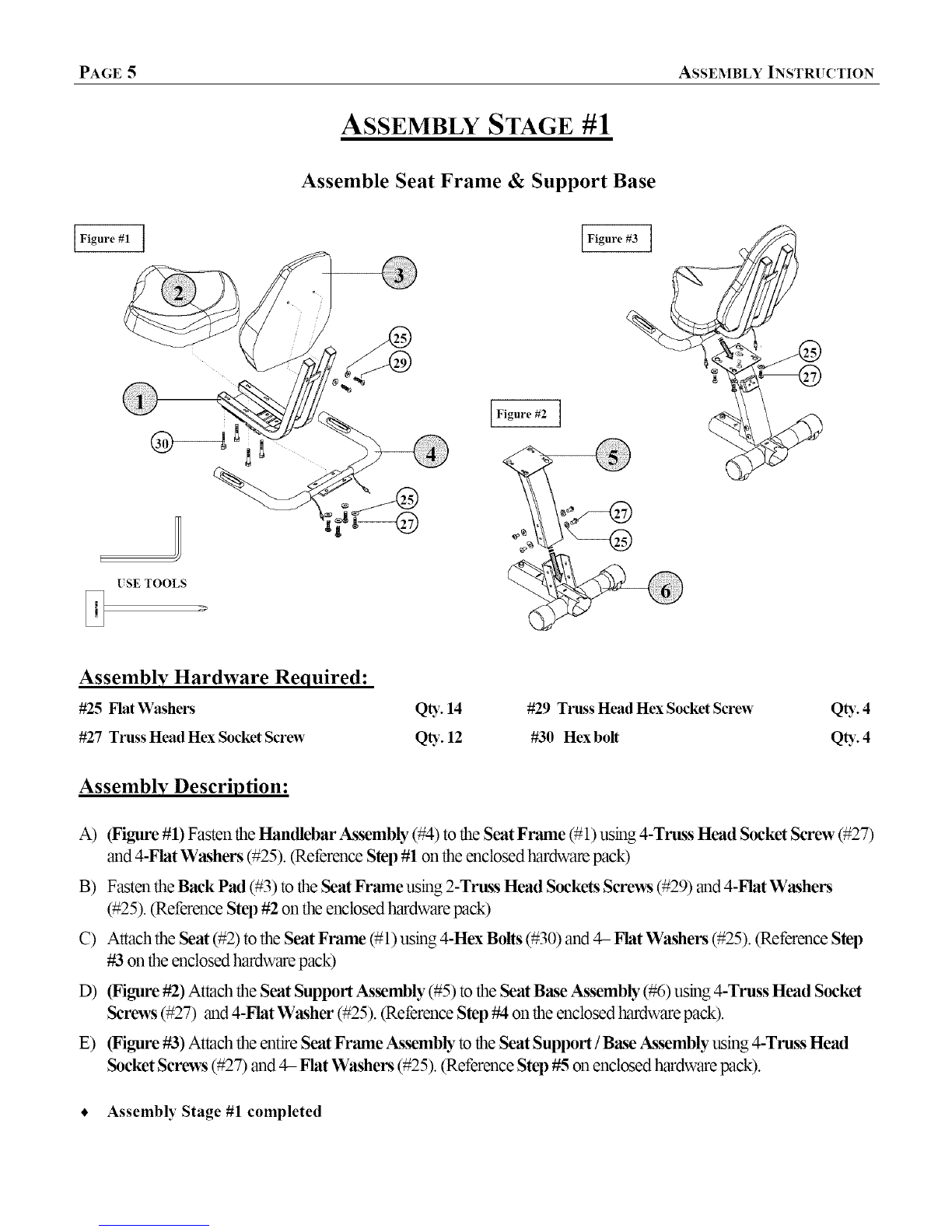
Attach Seat Rail /Seat Frame Assembly
I
USE TOOL
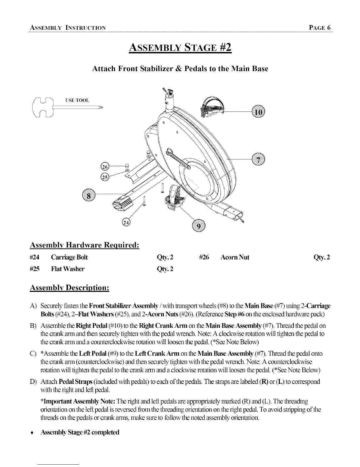
(able Splitter Box
Left Handlebar Cable Seat Rail ('able
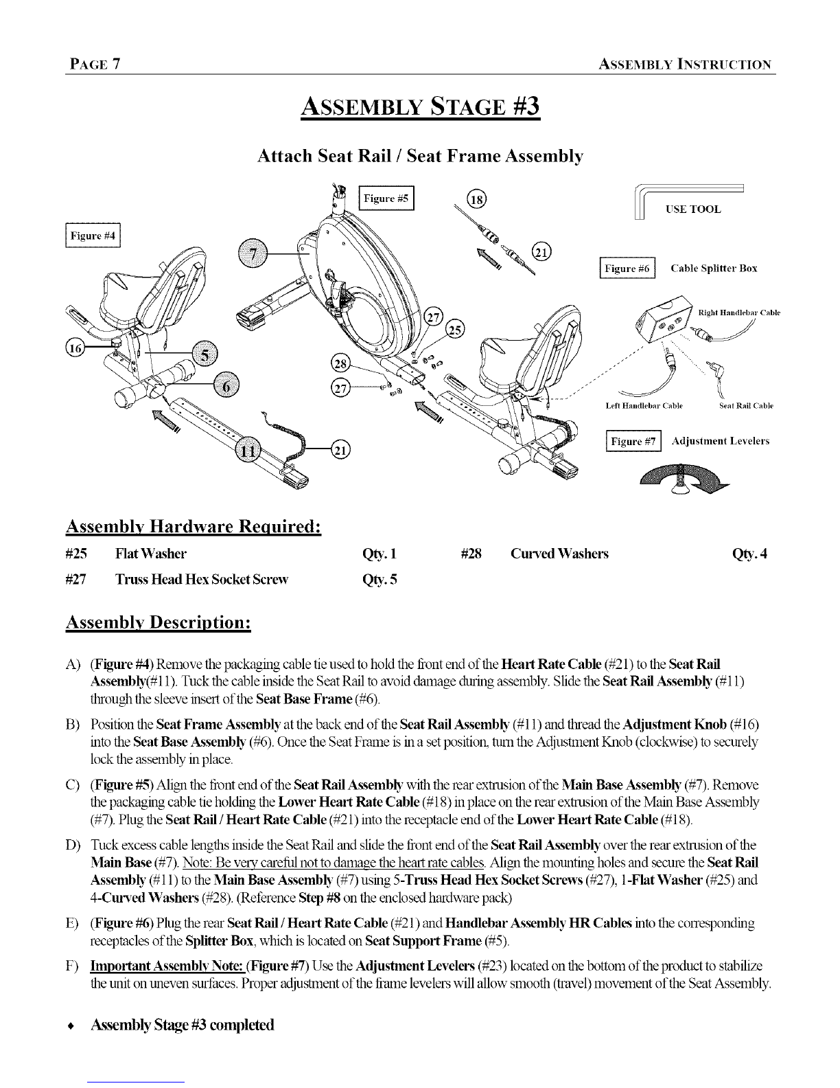
Adjustment Levelers
Assembly Hardware Required:
#25 Flat Washer Q_. 1
#27 Truss Head Hex Socket Screw Q_,. 5
#28 Curved Washers Q_. 4
Assembly Description:
A) (Figure #4) Remove the packaging cable tie used to hold the front end of the Heart Rate Cable (#21) to the Seat Rail
Assembb,(#11). Tuck the cable inside the Seat Rail to aw_iddamage during assembly. Slide the Seat Rail Assemb b"(#11)
through the sleeve insert of the Seat Base Frame (#6).
B) Position the Seat Frame Assembly at the back end of the Seat Rail Assembb" (#11) and thread the Adjustment Knob (#16)
into the Seat Base Assemb b" (#6). Once the Seat Frame is in a set Ix_sition,turn the Adjustment Knob (doclcwise) to securely
lock the assembly in place.
C) (Figure #5) Align the tkont end of the Seat Rail Assembb_ with the rear extrusion of the Main Base Assemb b" (#7). Remove
the packaging cable tie holding the Lower Heart Rate Cable (#18) in place on the rear extrusion of the Main Base Assembly
(#7). Plug the Seat Rail/Heart Rate Cable (#21) into the receptacle end of the Lower Heart Rate Cable (#18).
D) Tuck excess cable lengths reside the Seat Rail and slide the tkontend of the Seat Rail Assembly over the rear extrusion of the
_MainBase (#7). Note: Be very careful not to dama,oe the heart rate cables. Align the mounting holes and secure the Seat Rail
Assemb b"(#11) to the Main Base Assemb b" (#7) using 5-Truss Head I-Iex Socket Screws (#27), 1-Fht Washer (#25) and
4-Curved Washers (#28). _et_rence Step #8 on the enclosed hardware pack)
E) (Figure #6) Plug the rear Seat Rail /Heart Rate Cable (#21) and Handlebar Assembly HR Cables into the correslx_nding
receptacles of the Splitter Box, which is located on Seat Support Frame (#5).
F) Important Assembly Note: (Hgure #7) Use the Adjustment Levelers (#23) located on the bottom of the product to stabilize
the unit on uneven surthces. Proper adjus_tmentof the tkame levelers will allow smooth (travel) movement of the Seat Assembly.
• Assembly Stage #3 completed


 Service manual")