iv
3.8Installing Battery Cables.........................................................................................................18
3.9Reinstalling AC Dual-Live Wire Input Power Cables...................................................................18
3.9.1Installing AC Input Ground Cable................................................................................................19
3.9.2Installing AC Input Power Cable..................................................................................................20
4Verifying the Installation................................................................................................................23
4.1Checking Hardware Installation...............................................................................................23
4.2Checking Electrical Connections ..............................................................................................23
4.3Checking Cable Installation.....................................................................................................23
5Commissioning .............................................................................................................................23
5.1Connecting the AC Power Supply ............................................................................................23
5.2Setting the Display Language..................................................................................................23
5.3Setting the Date and Time......................................................................................................24
5.4Setting Battery Parameters.....................................................................................................24
5.5(Optional) Setting the Hibernation Parameter...........................................................................25
5.6Setting Communication Parameters.........................................................................................25
5.6.1Installing AC Input Power Cable..................................................................................................25
5.6.2Setting Parameters before Using the SNMP Management..............................................................26
5.7Connecting the Battery Supply................................................................................................28
6Maintenance.................................................................................................................................29
6.1Performing Routine Maintenance.............................................................................................29
6.2Troubleshooting Procedure.....................................................................................................29
ATechnical Specification ..................................................................................................................30
BElectrical Conceptual Diagram........................................................................................................32
CAssociations Between Alarms and Dry Contacts on the DCU..............................................................33
DAcronyms and Abbreviations..........................................................................................................34
Manufacturer’s Warranty.......................................................................................................................35
Document Control and Revision History...................................................................................................366
Table of Figures
Figure 1 - A36D Case Footprint...................................................................................................................1
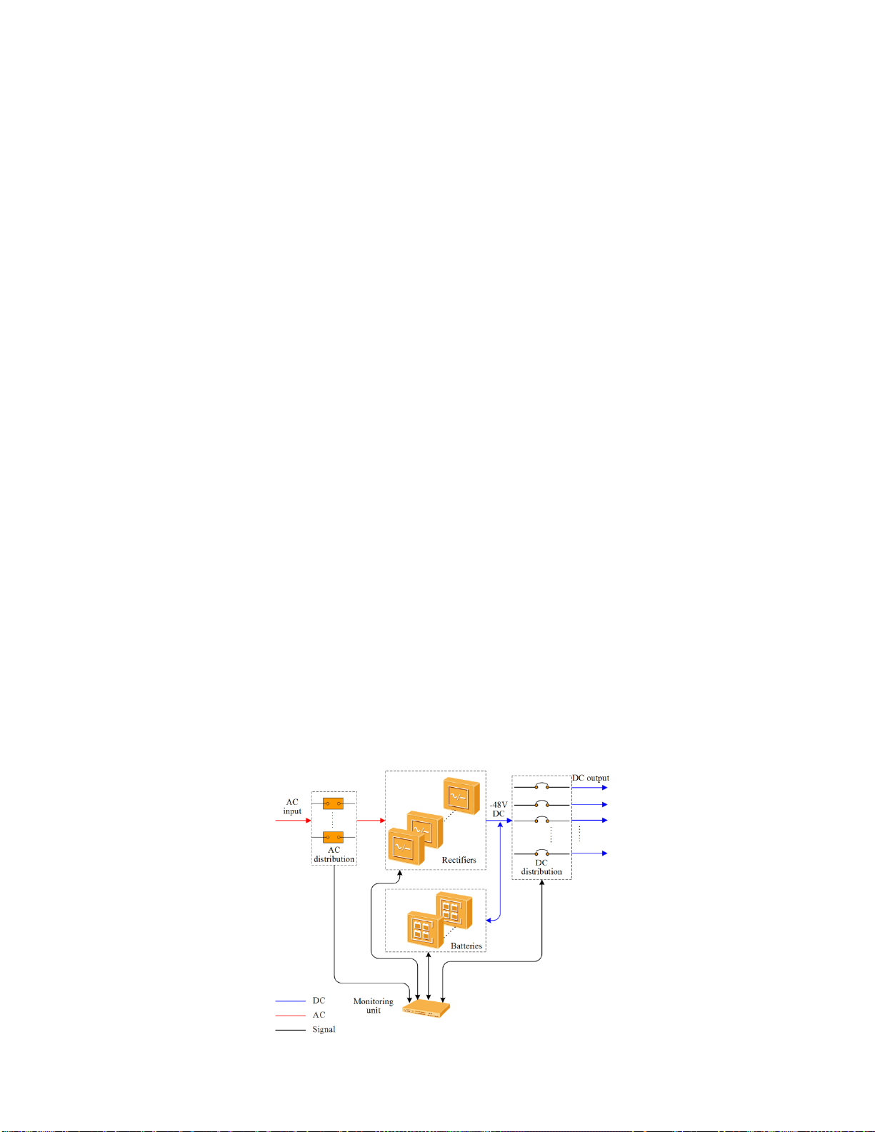
Figure 1 – Conceptual diagram ...................................................................................................................1
Figure 2 – DCPS ........................................................................................................................................2
Figure 3 – DC DCD for DCPS.......................................................................................................................3
Figure 4 – AC DCD for DCPS.......................................................................................................................3
Figure 5 – Rectifier ....................................................................................................................................4
Figure 6 – Rectifier Panel ...........................................................................................................................4
Figure 7 – DCSC........................................................................................................................................5
Figure 8 – DCSC panel ...............................................................................................................................6
Figure 9 – Pins in the FE port and RS485/RS232 port....................................................................................7
Figure 10 – DCU panel...............................................................................................................................8
Figure 11 – DCU pin numbers.....................................................................................................................9
Figure 12 – Installation Tools....................................................................................................................11
Figure 13 – Installing mounting ears (normal installation) ...........................................................................12