manuals.online logo
Brands
  1. Home
  2. •
  3. Brands
  4. •
  5. turck
  6. •
  7. Power Supply
  8. •
  9. turck PSD24EX User manual

turck PSD24EX User manual

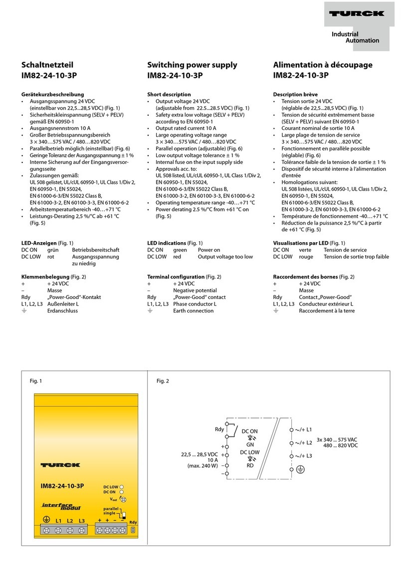
Weitere Unterlagen
Ergänzend zu diesem Dokument finden Sie im Internet unter
www.turck.com folgende Unterlagen:
■Datenblatt
■Handbuch excom – I/O-System für eigensichere Strom-
kreise
■Zulassungen
■Konformitätserklärungen (aktuelle Version)
Zu Ihrer Sicherheit
Bestimmungsgemäße Verwendung
Das Netzteil dient zur Spannungsversorgung des excom-I/O-
Systems.
Das Gerät ist ein Betriebsmittel in der kombinierten Ex-
Schutzart Ex m, Ex e und Exi und darf nur innerhalb des
I/O-Systems excom für eigensichere Stromkreise mit den
zugelassenen Modulträgern MT…-2G (PTB00ATEX 2194 U
und IECEx PTB 13.0040U) in Zone1 eingesetzt werden.
GEFAHR
Die vorliegende Anleitung enthält keine Informationen zum
Einsatz des Gesamtsystems.
Lebensgefahr durch Fehlanwendung!
Vorschriften des zugehörigen excom-Handbuchs
einhalten.
Die Geräte dürfen nur wie in dieser Anleitung beschrieben
verwendet werden. Jede andere Verwendung gilt als nicht
bestimmungsgemäß. Für daraus resultierende Schäden über-
nimmt Turck keine Haftung.
Allgemeine Sicherheitshinweise
■Nur fachlich geschultes Personal darf das Gerät montieren,
installieren, betreiben, parametrieren und instand halten.
■Das Gerät erfüllt die EMV-Anforderungen für den industri-
ellen Bereich. Bei Einsatz in Wohnbereichen Maßnahmen
treffen, um Funkstörungen zu vermeiden.
■Nur Geräte miteinander kombinieren, die durch ihre tech-
nischen Daten für den gemeinsamen Einsatz geeignet sind.
■Gerät vor der Montage auf Beschädigungen prüfen.
Hinweise zum Ex-Schutz
■Bei Einsatz des Gerätes im Ex-Bereich muss der Anwender
über Kenntnisse im Explosionsschutz (IEC/EN60079-14
etc.) verfügen.
■Nationale und internationale Vorschriften für den Explosi-
onsschutz beachten.
■Das Gerät nur innerhalb der zulässigen Betriebs- und
Umgebungsbedingungen (siehe Technische Daten und
Vorgaben durch die Ex-Zulassung) einsetzen.
Bei Einsatz in Zone1 und Zone2:
■Geräte in ein separat zugelassenes Gehäuse nach
IEC/EN60079-0 mit einer Schutzart mind. IP54 nach
EN60529 montieren.
Bei Einsatz im sicheren Bereich:
■Wenn Verschmutzungsgrad 2 nicht eingehalten wird:
Gerät in ein Schutzgehäuse mind. IP54 einbauen.
Produktbeschreibung
Geräteübersicht
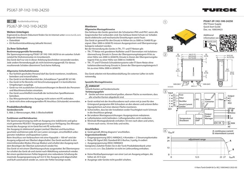
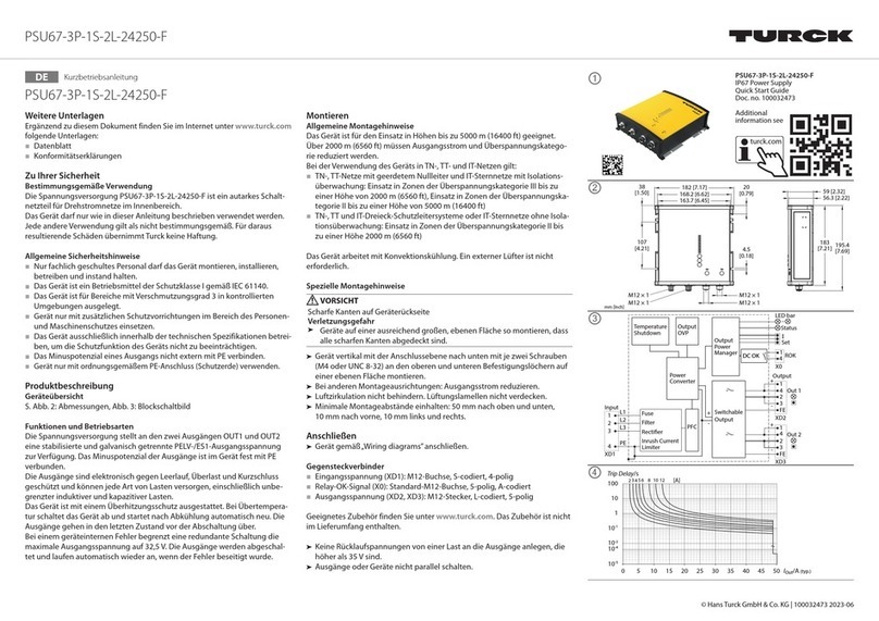
Siehe Abb.1: Geräteansicht, Abb.2: Abmessungen
Funktionen und Betriebsarten
Das 24-VDC-Netzteil versorgt alle angeschlossenen excom-
Module mit eigensicherer AC-Spannung.
Die Netzteile lassen sich einzeln oder redundant betreiben.
Im Redundanzbetrieb wird die Last auf beide Netzteile auf-
geteilt. Bei Ausfall eines Gerätes oder bei Unterbrechung der
Zuleitung übernimmt das intakte Gerät die Versorgung des
gesamten Systems. Zur Versorgung sollten unterschiedliche
Spannungsquellen genutzt werden.
DE Kurzbetriebsanleitung
PSD24EX
Montieren
ACHTUNG
Fehlerhafte Montage
Beschädigung der Steckverbinder
Netzteil gemäß Abb.3 senkrecht auf die Federleiste des
Modulträgers stecken.
 Netzteil gemäß Abb.4 auf dem Modulträger festschrauben.
Reihenfolge beachten.
Anschließen
Die Netzteile müssen vor der Montage an die externe Ver-
sorgungsspannung am Modulträger über die Ex e-Klemmen
angeschlossen werden. Zum Anschluss die Kurzbetriebsanlei-
tung des Modulträgers beachten.
In Betrieb nehmen
Nach Anschluss der Leitungen und Montage des Netzteils
geht das Gerät automatisch in Betrieb.
Betreiben
Zum einwandfreien Betrieb müssen alle Befestigungsschrau-
ben festgedreht sein.
Die Netzteile können auch während des laufenden Betriebs
gezogen oder gesteckt werden.
LEDs
LED Zustand Funktion
Uin grün Gerät betriebsbereit
aus Gerät nicht betriebsbereit
Uout grün Energieversorgung fehlerfrei
rot Energieversorgung fehlerhaft
Außer Betrieb nehmen
 Befestigungsschrauben lösen.
 Gerät vom Modulträger entfernen.
Reparieren
Das Gerät ist nicht zur Reparatur durch den Benutzer vor-
gesehen. Sollte das Gerät defekt sein, nehmen Sie es außer
Betrieb. Bei Rücksendung an Turck beachten Sie bitte unsere
Rücknahmebedingungen.
Entsorgen
Die Geräte müssen fachgerecht entsorgt werden und
gehören nicht in den normalen Hausmüll.
Installing
CAUTION
Incorrect mounting
Damage to the connector possible
Attach the power supply module vertically to the multi-
point connector of the module rack, as shown in fig. 3.
 Screw the power supply module onto the module rack as
shown in fig.4. Follow the indicated sequence.
Connection
The power supply modules must be connected to the exter-
nal supply voltage on the module rack via the Ex-e terminals
before mounting. For details of how to connect the power
supply modules, refer to the Quick Start Guide for the module
rack.
Commissioning
The device is operational automatically once the cables are
connected and the power supply is mounted.
Operation
All mounting screws must be sufficiently tightened to ensure
fault-free operation.
The power supply modules can also be connected or discon-
nected during operation.
LEDs
LED State Function
Uin Green Device is operational
Off Device is not operational
Uout Green Power supply fault-free
Red Power supply faulty
Decommissioning
 Loosen mounting screws.
 Remove the device from the module rack.
Repair
The device must not be repaired by the user. The device must
be decommissioned if it is faulty. Observe our return accep-
tance conditions when returning the device to Turck.
Disposal
The devices must be disposed of properly and do not
belong in the domestic waste.
EN Quick Start Guide
PSD24EX
Other documents
Besides this document, the following material can be found
on the Internet at www.turck.com:
■Data sheet
■excom manual — I/O system for intrinsically safe circuits
■Approvals
■Declarations of conformity (current version)
For your safety
Intended use
The power supply module is used for the power supply of the
excom I/O system.
The device is a piece of equipment from combined explosion
protection categories Ex m, Ex e and Ex i and may be used
only as part of the excom I/O system for intrinsically safe cir-
cuits with the approved module racks MT…-2G (PTB 00 ATEX
2194 U and IECEx PTB 13.0040U) in zone 1.
DANGER
These instructions do not provide any information about use
of the overall system.
Danger to life due to misuse!
Observe the regulations contained in the associated
excom manual.
The devices must only be used as described in these instruc-
tions. Any other use is not in accordance with the intended
use. Turck accepts no liability for any resulting damage.
General safety instructions
■The device must only be mounted, installed, operated,
parameterized and maintained by trained and qualified
personnel.
■The device meets the EMC requirements for industrial
areas. When used in residential areas, take measures to
prevent radio interference.
■Only combine devices that are suitable for joint use based
on their technical data.
■Check the device for damage before mounting.
Notes on explosion protection
■When using the device in Ex areas, the user must have
knowledge of explosion protection (IEC/EN60079-14 etc.).
■Observe national and international regulations for explo-
sion protection.
■Only use the device within the permissible operating and
ambient conditions (see technical data and Ex approval
specifications).
When used in zone1 and zone2:
■Mount the devices in a separately approved enclosure in
accordance with IEC/EN60079-0 with a degree of protec-
tion of at least IP54 in accordance with EN60529.
When used in safe areas:
■If pollution degree 2 is not complied with:
Install the device in an enclosure with a degree of protec-
tion of at least IP54.
Product description
Device overview
See fig.1: Device view, fig.2: Dimensions
Functions and operating modes
The 24-VDC power supply module supplies all connected
excom modules with intrinsically safe AC voltage.
The power supply modules can be operated individually or
redundantly.
In redundant mode, the load is distributed between both
power supply modules. In case of a power cut or failure of
one device, the intact device provides the power supply for
the whole system. Different power sources should be used for
the supply.
© Hans Turck GmbH & Co. KG | D300333 2023-07 V3.0
PSD24EX
①PSD24EX
Power Supply Module
Quick Start Guide
Doc. no. D300333 2307
Additional
information see
②
106
45
145
25 4x M4
155
③No Yes
④


Wiring diagram
turck.com
24 VDC
+DC
–AC
Documents supplémentaires
Sur le site www.turck.com, vous trouverez les documents
suivants qui complètent ce guide:
■Fiche technique
■Manuel du système d’E/S excom pour circuits à sécurité
intrinsèque
■Homologations
■Déclarations de conformité (version actuelle)
Pour votre sécurité
Utilisation conforme
Le module d’alimentation est utilisé pour l’alimentation en
tension du système d’E/S excom.
L’appareil est un équipement appartenant au mode de pro-
tection Ex combiné de type Ex m, Ex e et Ex i et ne peut être
utilisé qu’au sein du système E/S excom pour des circuits à
sécurité électrique intrinsèque avec les supports de modules
autorisés MT… -2G (PTB 00 ATEX 2194 U et IECEx PTB
13.0040U) dans la zone 1.
DANGER
Ces instructions ne fournissent aucune information sur l'utili-
sation de l'ensemble du système.
Danger de mort en cas d'utilisation non conforme!
Respectez les consignes du manuel excom correspon-
dant.
Les appareils doivent exclusivement être utilisés conformé-
ment aux instructions figurant dans ce guide. Toute autre
utilisation est considérée comme non conforme. Turck
décline toute responsabilité en cas de dommages causés par
une utilisation non conforme.
Consignes de sécurité générales
■Seul un personnel spécialement formé et qualifié peut
monter, installer, exploiter et paramétrer l’appareil, ainsi
qu’en effectuer la maintenance.
■L’appareil répond aux exigences CEM pour les zones indus-
trielles. En cas d’utilisation dans des zones résidentielles,
des mesures doivent être prises pour éviter les interfé-
rences radio.
■Combinez uniquement des appareils adaptés à une utilisa-
tion conjointe en fonction de leurs données techniques.
■Vérifiez que l’appareil n’est pas endommagé avant le
montage.
Remarques sur la protection Ex
■En cas d’utilisation de l’appareil dans des zones Ex, vous
devez disposer des connaissances requises en matière de
protection contre les explosions (CEI/EN60079-14, etc.).
■Respectez les consignes nationales et internationales
relatives à la protection contre les explosions.
■Utilisez l’appareil uniquement dans un environnement et
dans les conditions de fonctionnement autorisés (voir les
caractéristiques techniques et les exigences des homolo-
gationsEx).
Utilisation des appareils en zone1 et en zone2:
■Montez les appareils dans un boîtier séparé homologué
conformément à la normeCEI/EN60079-0 et avec un
indice de protectionIP54 minimum conformément à la
norme EN60529.
Utilisation en zone sécurisée:
■Si le degré de pollution2 n’est pas respecté:
montez l’appareil dans un boîtier avec un indice de protec-
tionIP54 minimum.
FR Guide d'utilisation rapide
PSD24EX
Description du produit
Aperçu de l’appareil
Voir fig.1: vue de l’appareil, fig.2: dimensions
Fonctions et modes de fonctionnement
Le module d’alimentation 24VCC fournit une tension CA à
sécurité intrinsèque à tous les modules excom connectés.
Les modules d’alimentation peuvent fonctionner de manière
simple ou redondante.
En fonctionnement redondant, la charge est répartie entre les
deux modules d’alimentation. En cas de coupure de courant
ou de défaillance de l’un des appareils, l’appareil intact
prend en charge l’alimentation de l’ensemble du système.
Différentes sources de tension peuvent être utilisées pour
l’alimentation.
Installation
PRUDENCE
Montage incorrect
Risque d‘endommagement du connecteur
Fixez le module d‘alimentation verticalement sur le
contre-connecteur du support de module conformé-
ment à la fig. 3.
 Vissez le module d’alimentation sur le support de module
conformément à la fig.4. Suivez l’ordre indiqué.
Raccordement
Les modules d’alimentation doivent être connectés à la
tension d’alimentation externe du support de module via les
bornes Ex-e avant le montage. Pour plus d’informations sur
la connexion des modules d’alimentation, reportez-vous au
guide d’utilisation rapide du support de module.
Mise en service
L’appareil est automatiquement opérationnel après raccorde-
ment des câbles et montage de l’alimentation.
Fonctionnement
Pour un fonctionnement sans erreur, toutes les vis de fixation
doivent être vissées fermement.
Les modules d’alimentation peuvent également être connec-
tés ou déconnectés en cours de fonctionnement.
LED
LED Etat Fonction
Uin Vert L'appareil est opérationnel
Off L'appareil n'est pas opérationnel
Uout Vert Alimentation sans défaut
Rouge Alimentation défectueuse
Mise hors service
 Desserrez les vis de fixation.
 Retirez l’appareil du support de module.
Réparation
L’appareil ne doit pas être réparé par l’utilisateur. En cas de
dysfonctionnement, mettez l’appareil hors service. En cas de
retour à Turck, veuillez respecter les conditions de retour.
Mise au rebut
Les appareils doivent être mis au rebut de manière
appropriée et ne doivent pas être jetés avec les ordures
ménagères.
Descrição do produto
Visão geral do produto
Veja a fig. 1: Visão do dispositivo, Fig. 2: Dimensões
Funções e modos de operação
Os módulos da fonte de alimentação de 24 VCC alimentam
todos os módulos excom conectados com uma tensão CA
intrinsecamente segura.
Os módulos das fontes de alimentação podem ser operados
individualmente ou no modo redundante.
No modo redundante, a carga é distribuída entre os dois
módulos de alimentação de energia. Em caso de falha ou
corte na alimentação de um dispositivo, o dispositivo intacto
fornece alimentação para todo o sistema. Diferentes fontes
de alimentação devem ser usadas na alimentação.
Instalação
CUIDADO
Montagem incorreta
Possível dano ao conector
Conecte o módulo da fonte de alimentação verticalmen-
te ao conector multiponto do rack do módulo, conforme
mostrado na fig. 3.
 Fixe o módulo da fonte de alimentação no rack de módulo,
conforme mostrado na fig. 4 Siga a sequência indicada.
Conexão
Os módulos da fonte de alimentação devem ser conectados à
tensão de alimentação externa no rack do módulo por meio
dos terminais Ex-e antes da montagem. Para obter detalhes
sobre como conectar os módulos da fonte de alimentação,
consulte o Guia de início rápido do rack do módulo.
Comissionamento
O dispositivo fica automaticamente operacional assim que os
cabos são conectados e a fonte de alimentação é montada.
Operação
Todos os parafusos de montagem devem estar suficiente-
mente apertados para garantir uma operação sem falhas.
Os módulos da fonte de alimentação também podem ser
conectados ou desconectados durante a operação.
LEDs
LED Estado Função
Uin Verde O dispositivo está em
funcionamento
Desligado O dispositivo não está
funcionando
Uout Verde Fonte de alimentação sem
defeitos
Vermelho Módulo de alimentação com
defeito
Desativação
 Solte os parafusos de montagem.
 Remova o dispositivo do rack do módulo.
Reparo
O dispositivo não deve ser reparado pelo usuário. Retire o
dispositivo de operação em caso de defeito. Observe nossas
condições para aceitação de devolução ao devolver o dispo-
sitivo à Turck.
Descarte
Os dispositivos devem ser descartados corretamente e
não em lixo doméstico.
PT Guia de Início Rápido
PSD24EX
Outros documentos
Além deste documento, o material a seguir pode ser encon-
trado na Internet em www.turck.com:
■Ficha técnica
■manual do excom – Sistema de E/S para circuitos intrinse-
camente seguros
■Homologações
■Declarações de conformidade (versão atual)
Para sua segurança
Finalidade de uso
O módulo da fonte de alimentação é usado para alimentar o
sistema de E/S excom.
O dispositivo é um equipamento com categorias de proteção
contra explosões Ex m, Ex e, e Ex i combinadas, e pode ser
usado apenas como parte do sistema de E/S excom para
circuitos intrinsecamente seguros com os racks de módulo
MT…-2G (PTB 00 ATEX 2194 U e IECEx PTB 13.0040U) aprova-
dos na zona 1.
PERIGO
Essas instruções não contêm qualquer informação sobre o
uso do sistema geral.
Risco de morte devido ao mau uso!
Siga as regulamentações contidas no manual do excom
correspondente.
Os dispositivos devem ser usados apenas como descrito
nessas instruções. Qualquer outro uso não está de acordo
com o pretendido. A Turck não se responsabiliza por danos
resultantes.
Instruções gerais de segurança
■O dispositivo só deve ser montado, instalado, operado,
parametrizado e mantido por pessoal treinado profissio-
nalmente.
■O dispositivo atende aos requisitos de EMC para áreas
industriais. Em caso de uso em áreas residenciais, tome
medidas para evitar interferência de rádio.
■Somente combine dispositivos que sejam tecnicamente
adequados para uso conjunto, baseados em seus dados
técnicos.
■Verifique se há danos no dispositivo antes de montá-lo.
Notas de proteção contra explosão
■Ao usar o dispositivo em áreas Ex, o usuário também deve-
rá ter conhecimento sobre proteção contra explosões
(IEC/EN 60079-14, etc.).
■Siga os regulamentos nacionais e internacionais sobre
proteção contra explosão.
■Use o dispositivo somente em condições ambientais e
de operação permitidas (consulte os dados técnicos e os
requisitos de homologação Ex).
Uso dos dispositivos nas zonas 1 e 2:
■Monte os dispositivos em um gabinete aprovado de acor-
do com a IEC/EN 60079-0, com um grau de proteção de
pelo menos IP54, de acordo com a EN 60529.
Quando usado em áreas seguras:
■Se o grau de poluição 2 não estiver em conformidade com:
Instale o dispositivo em um gabinete com um tipo de
proteção de pelo menos IP54.
Hans Turck GmbH & Co. KG | Witzlebenstraße 7, 45472 Mülheim an der Ruhr, Germany | Tel. +49 2084952-0 | Fax +49 208 4952-264 | [email protected] | www.turck.com © Hans Turck GmbH & Co. KG | D300333 2023-07 V3.0
PSD24EX
Certication data | Technical data
Approvals and markings
Approvals
PTB 00 ATEX 2193 ÉII 2 G Ex eb mb [ib Gb] IIC T4 Gb
TÜV 22 UKEX 7115
IECEx PTB 13.0039 Ex eb mb [ib Gb] IIC T4 Gb
电源模块
󼔔󼜹󻺸󻦸󺮥󺯌󺪜󻠡󽋸󺬉󻹌󼍡󼋤󼖠󻪐󺨐󺪑󻂄
󼋤󼖠󼔔󼜹󻨤󽏔󾙓󾙕󾙖󾙒󾙓󾙖󾙒
󼋤󼖠󽋸󾘥󻹈󼑅󼓠󾘥󼒠󽋸󾘥󼘌󺨐󻦸󺮥󻆸󾘥󼔔󼜹󻺸󾘥󼧔󼘌
FM18US0068X
FM18CA0033X
Class I, Division 2, Groups A, B, C, D; T4
Class I Zone 1 AEx/Ex e mb [ib], Group IIC; T4
Install per Control Drawing IS-2500
Ambient temperature Tamb: -20…+70 °C
Electrical data
Maximum r. m. s. AC or DC voltage Um60 V
Technical data
Type designation PSD24EX
ID 6881721
Supply voltage 18…32 VDC
Nominal voltage 24 VDC
Power consumption 75 W
Output power ≤ 60 W
Galvanic isolation Galvanically isolated input and output circuit
Connection mode Module, plugged on rack
Protection class IP50
Relative humidity ≤ 93 % at 40 °C acc. to
EN 60068-2-78
EMC Acc. EN 61326-1
Acc. to Namur NE21
0102
2503
설치
주의
󼔴󻡗󻆸󾘥󻻀󼯴
커넥터 손상 가능
󺮔󻝘󾙕󺪘󾘥󺦵󼔐󾘥󻡄󻉤󾘥󻔵󼓴󾘥󻟜󽂌󽆈󼔔󽁔󾘥󼲀󺻁󼻌󼍬󾘥󽂨󼑨󾘥󻺸󽊨
󻔘󼔐󾘥󻡄󻉤󼓠󾘥󻾴󼝝󼓘󻗸󾘥󻬜󼧅󽋴󼂉󼁸󼏀
 󽂨󼑨󾘥󻺸󽊨󻔘󼔐󾘥󻡄󻉤󼓠󾘥󺮔󻝘󾙖󼏜󾘥󺦵󼔐󾘥󻡄󻉤󾘥󻔵󼍬󾘥󺸴󻹈󻗸󾘥󺩼󼖱
󽋴󼂉󼁸󼏀󽇸󼁸󻆸󾘥󻾸󻺸󻜘󾘥󻋌󻜐󼂉󼁸󼏀
연결
󽂨󼑨󾘥󻺸󽊨󻔘󼔐󾘥󻡄󻉤󼓜󾘥󻻀󼯴󽋴󺯌󾘥󼖠󼍬󼻌󻦔󺺬󼓠󾘥󼽑󽌐󾘥󻡄󻉤
󻔵󼓴󾘥󼐔󻬜󾘥󺪑󺮥󾘥󼖠󼋱󼍬󾘥󼎌󺩌󽌐󼌘󾘥󽌅󻁤󻂀󽂨󼑨󾘥󻺸󽊨󻔘󼔐󾘥󻡄󻉤󼓴
󼎌󺩌󾘥󻧅󻨱󼍬󾘥󻂜󽋸󾘥󼔬󻻔󽋸󾘥󺹐󼑅󼓜󾘥󻡄󻉤󾘥󻔵󼍬󾘥󻂜󽋸󾘥󻯼󻜔󾘥󼁸󼔭󾘥󺦜
󼔐󻉸󻜘󾘥󼧔󼘌󽋴󼂉󼁸󼏀
시운전
󼲜󼔐󻮰󼓠󾘥󼎌󺩌󽋴󺩼󾘥󽂨󼑨󾘥󻺸󽊨󻔘󼔐󻜘󾘥󻻀󼯴󽋴󻠐󾘥󼕁󼯴󺦜󾘥󼔬󻅵󼓘󻗸
󼔭󻅵󾘥󺦜󻁁󽌐󼝭󻁤󻂀
작동
󻡄󻉼󾘥󻻀󼯴󾘥󺸴󻹈󻀰󾘥󼏀󻛴󾘥󼍢󼔐󾘥󼔭󻅵󽋼󾘥󻾴󾘥󼔤󻅠󻗹󾘥󼭅󻬠󽔤󾘥󼘌󼎈󼌘
󽌅󻁤󻂀
󻎬󽋸󾘥󽂨󼑨󾘥󻺸󽊨󻔘󼔐󾘥󻡄󻉤󼓜󾘥󼔭󻅵󾘥󼚭󼍬󾘥󼎌󺩌󾘥󻎬󻀰󾘥󻬠󻝈󽋼󾘥󻾴󻅠
󼔤󼁑󻁤󻂀
LED
LED 상태 기능
 󺼕󻹥 󼕁󼯴󾘥󼔭󻅵󾘥󺦜󻁁
 󼕁󼯴󾘥󼔭󻅵󾘥󻬤󺦜
 󺼕󻹥 󽂨󼑨󾘥󻺸󽊨󻔘󼔐󾘥󺩼󼕁󾘥󼍢󼓨
󼖝󻹥 󽂨󼑨󾘥󻺸󽊨󻔘󼔐󾘥󺩼󼕁
설치 해체
 󻻀󼯴󾘥󺸴󻹈󻜘󾘥󽈔󼂉󼁸󼏀
 󻡄󻉤󾘥󻔵󼍬󻺸󾘥󼕁󼯴󻜘󾘥󻬠󻝈󽋴󼂉󼁸󼏀
수리
󼔐󾘥󼕁󼯴󻀰󾘥󻹈󼑅󼔬󺦜󾘥󻾴󻝈󽌐󻺸󻀰󾘥󼋤󾘥󻇅󻁤󻂀󼔐󾘥󼕁󼯴󼍬󾘥󺩼󼕁󼔐
󻦸󻹹󽋸󾘥󺩙󼑌󾘥󻻀󼯴󾘥󽌐󼩐󽌐󼌘󾘥󽌅󻁤󻂀󼕁󼯴󻜘󾘥󼻌󼸈󼍬󾘥󻦴󽈤󽋼󾘥󺩙
󼑌󻦴󽈤󾘥󼁕󼔔󾘥󼘌󺨐󼓠󾘥󼚜󻾴󽋴󼂉󼁸󼏀
폐기
󼕁󼯴󻀰󾘥󼖝󼖤󽋴󺨨󾘥󽅬󺯌󽌐󼌘󾘥󽋴󻠌󾘥󺦜󼖱󼑅󾘥󽅬󺯌󻣘󼍬󾘥󽌐󻂕󽋴
󼝜󾘥󼋦󼁑󻁤󻂀
KO 빠른 시작 가이드
PSD24EX
기타 문서
󼔐󾘥󻣔󻺸󾘥󼐔󼍬󻅠󾘥󻂀󼓨󺪘󾘥󺦵󼓜󾘥󼔬󻙨󻜘󾘥󼔔󼻌󺻓www.turck.com
󼍬󻺸󾘥󽏱󼔔󽋼󾘥󻾴󾘥󼔤󼁑󻁤󻂀
■󻄌󼔐󼻌󾘥󼁸󽁔
■󻞀󻀐󼍘󻪔󼝤󾘥󼋤󼖠󾘥󽐨󻗸󼑅󼁸󼁀󼻸
■󼔔󼜹
■󼖝󽌅󻻍󾘥󻺼󼍔󽎠󼕈󾘥󻨠󼖠
사용자 안전 정보
사용 목적
󽂨󼑨󾘥󻺸󽊨󻔘󼔐󾘥󻡄󻉤󼓜󼁸󼁀󼻸󼓴󾘥󼖠󼑬󾘥󺪑󺮥󼓠󾘥󼒠󽌐
󻹈󼑅󻇅󻁤󻂀
󼔐󾘥󼕁󼯴󻀰󾘥󽆉󻦸󾘥󻧅󼝜󾘥󻨰󼚘󼓴󻦫󻜘󾘥󽏘󽌅󽋸󾘥󼕁󻯠
󻗸󾙓󼘡󾘥󼒠󽍴󾘥󼝜󼎉󼍬󻺸󾘥󼁕󼔔󻆸󾘥󻡄󻉤󾘥󻔵󾙜󾙔󾙒󾙒
󾙔󾙓󾙛󾙖󻦫󾙓󾙕󾙒󾙒󾙖󾙒󼏜󾘥󽌄󺱴󾘥󻪔󼝤󾘥󼋤󼖠󾘥󽐨󻗸󼑅
󼁸󼁀󼻸󼓴󾘥󼔘󻬜󻗸󻝨󾘥󻹈󼑅󽋼󾘥󻾴󾘥󼔤󼁑󻁤󻂀
위험
󼔐󾘥󼝜󼰄󼍬󻀰󾘥󼖠󼩐󾘥󼁸󼁀󼻸󾘥󻹈󼑅󼍬󾘥󺪜󽋸󾘥󼍐󻌼󽋸󾘥󼖱󻪐󻅠󾘥󼖸󺪑󻆴
󼍐󾘥󼔤󼝜󾘥󼋦󼁑󻁤󻂀
부적절하게 사용할 경우 생명이 위험할 수 있습니다!
󺪜󻗄󻞀󻀐󼍘󼍬󾘥󻾴󻗹󻆸󾘥󼝜󼰄󼓠󾘥󻋌󻜐󼂉󼁸󼏀
󼔐󾘥󼕁󼯴󻀰󾘥󼔐󾘥󼝜󼰄󼍬󻺸󾘥󻻀󻠡󽋸󾘥󻡅󼖝󼓘󻗸󻝨󾘥󻹈󼑅󽌐󼌘󾘥󽌅󻁤󻂀󺯌
󼹜󾘥󻂀󻜔󾘥󻧅󼁹󼓘󻗸󾘥󻹈󼑅󽋴󻀰󾘥󺨟󼓜󾘥󻹈󼑅󾘥󻡅󼖝󼓠󾘥󻋌󻜐󼝜󾘥󼋦󻀰󾘥󺨟
󼔡󻁤󻂀󼻌󼸈󻀰󾘥󺮔󻗸󾘥󼔔󽌐󾘥󻦸󻹹󽋸󾘥󻼬󽌐󼍬󾘥󻂜󽌐󾘥󼧡󼔠󼓠󾘥󼝜󼝜󾘥󼋦
󼁑󻁤󻂀
일반 안전 지침
■󼖠󻣔󼖝󼔔󾘥󽑤󻗄󼓠󾘥󻦷󼓜󾘥󻾵󻗄󻆸󾘥󺯌󻾼󼔬󻝨󾘥󼔐󾘥󼕁󼯴󼓴󾘥󼘌󻝙󻻀
󼯴󼔭󻅵󻞀󺦸󾘥󻩜󻾴󾘥󻻀󼖱󾘥󻦫󾘥󼒼󼝜󻪐󻾴󻜘󾘥󻾴󽌥󽌐󼌘󾘥󽌅󻁤󻂀
■󼔐󾘥󼕁󼯴󻀰󾘥󻹌󼍡󾘥󻬠󼌘󼓴󼐰󺬈󾘥󻹈󽌉󼓠󾘥󼭅󼘍󽌅󻁤󻂀󼚘󺨌
󼝜󼎉󼍬󻺸󾘥󻹈󼑅󽋴󻀰󾘥󺩙󼑌󾘥󻣐󻺼󾘥󺦠󻻉󼓠󾘥󻧅󼝜󽋴󺯌󾘥󼒠󽋸󾘥󼘌󼯴󻜘
󼮄󽋴󼂉󼁸󼏀
■󺯌󻾼󾘥󻄌󼔐󼻌󻜘󾘥󻦰󼹱󼓘󻗸󾘥󺪑󻅵󾘥󻹈󼑅󼍬󾘥󼖝󽌅󽋸󾘥󼕁󼯴󻝨󾘥󼘌󽌅󽋴
󼂉󼁸󼏀
■󻻀󼯴󾘥󼖠󼍬󾘥󼕁󼯴󺦜󾘥󻼬󻹝󻆴󼍤󻀰󼝜󾘥󽏱󼔔󽋴󼂉󼁸󼏀
폭발 방지 참고 사항
■󽆉󻦸󾘥󼒠󽍴󾘥󼝜󼎉󼍬󻺸󾘥󼔐󾘥󼕁󼯴󻜘󾘥󻹈󼑅󽋼󾘥󺩙󼑌󾘥󻹈󼑅󼔬󻀰󾘥󽆉󻦸
󻧅󼝜󾙘󾙒󾙒󾙙󾙛󾙓󾙖󻊍󼍬󾘥󻂜󽋸󾘥󼝜󼁹󼔐󾘥󼔤󼍐󼌘󾘥󽌅󻁤󻂀
■󽆉󻦸󾘥󻧅󼝜󼍬󾘥󺪜󽋸󾘥󺬉󺹐󾘥󻦫󾘥󺬉󼖸󾘥󺭸󼖱󼓠󾘥󼚜󻾴󽋴󼂉󼁸󼏀
■󽍤󼑅󻆴󻀰󾘥󼔭󻅵󾘥󻦫󾘥󼚘󻩜󾘥󼘌󺨐󾘥󺹐󼍬󻺸󻝨󾘥󼕁󼯴󻜘󾘥󻹈󼑅󽋴󼂉󼁸󼏀
󺯌󻾼󾘥󻄌󼔐󼻌󾘥󻦫󾘥󻧅󽆉󾘥󼔔󼜹󻺸󾘥󻹈󼌭󾘥󼧔󼘌
󾙓󼘡󾘥󻦫󾙔󼘡󾘥󼒠󽍴󾘥󼝜󼎉󾘥󺹐󾘥󼕁󼯴󾘥󻹈󼑅
■󾙘󾙒󾙗󾙔󾙛󼍬󾘥󻋌󻔘󾘥󻪐󽏔󾘥󻊍󺮥󼔐󾙗󾙖󼔐󻹝󼔔󾙘󾙒󾙒󾙙󾙛
󾙒󺭸󺩅󼓴󾘥󻩠󻅠󾘥󼁕󼔔󾘥󼐔󽌄󼍬󾘥󼕁󼯴󻜘󾘥󻻀󼯴󽋴󼂉󼁸󼏀
󼋤󼖠󾘥󼝜󼎉󼍬󻺸󾘥󻹈󼑅󽋼󾘥󺩙󼑌
■󼏀󼎘󻅠󾙔󻜘󾘥󼚜󻾴󽋴󼝜󾘥󼋦󼓠󾘥󺩙󼑌
󾙗󾙖󼔐󻹝󼓴󾘥󻪐󽏔󾘥󻊍󺮥󼔐󾘥󼔤󻀰󾘥󻪐󽏔󾘥󽋴󼑌󼝱󼍬󾘥󼕁󼯴󻜘󾘥󻻀󼯴
󽋴󼂉󼁸󼏀
제품 설명
장치 개요
󺮔󻝘󾙓󼕁󼯴󾘥󻅠󻠐󺮔󻝘󾙔󼯴󻾴󻜘󾘥󼧔󼘌󽋴󼂉󼁸󼏀
기능 및 작동 모드
󾙔󾙖󽂨󼑨󾘥󻺸󽊨󻔘󼔐󾘥󻡄󻉤󼓜󾘥󼎌󺩌󻆸󾘥󻡄󻉼󻡄󻉤󼍬󾘥󻪔
󼝤󾘥󼋤󼖠󼖠󼋱󼓠󾘥󺪑󺮥󽌅󻁤󻂀
󽂨󼑨󾘥󻺸󽊨󻔘󼔐󾘥󻡄󻉤󼓜󾘥󺦸󻩠󼖝󼓘󻗸󾘥󻎬󻀰󾘥󼔐󼚭󼓘󻗸󾘥󼔭󻅵󽋼󾘥󻾴󾘥󼔤
󼁑󻁤󻂀
󼔐󼚭󽏰󾘥󻡄󻉸󼍬󻺸󻀰󾘥󻬜󽋴󺦜󾘥󻇬󾘥󽂨󼑨󾘥󻺸󽊨󻔘󼔐󾘥󻡄󻉤󻗸󾘥󻬠󻹌󻇅󻁤
󻂀󼖱󼖠󼔐󾘥󻦸󻹹󽋴󺨌󺸴󾘥󽋴󺸴󼓴󾘥󼕁󼯴󺦜󾘥󺩼󼕁󾘥󺸼󾘥󺩙󼑌󺩼󼕁󼔐󾘥󺸴
󼝜󾘥󼋦󼓜󾘥󼕁󼯴󺦜󾘥󼖠󼩐󾘥󼁸󼁀󼻸󼍬󾘥󽂨󼑨󾘥󻺸󽊨󻔘󼔐󻜘󾘥󼖸󺪑󽌅󻁤󻂀󽂨
󼑨󾘥󻺸󽊨󻔘󼔐󼍬󾘥󻂀󻜔󾘥󼖠󻗁󾘥󻼨󼁀󻜘󾘥󻹈󼑅󽌐󼌘󾘥󽌅󻁤󻂀
其他文档
除了本文档之外,还可在www.turck.com网站上查看以下
材料:
■数据表
■excom手册—本安电路的I/O系统
■认证
■合规声明(最新版本)
安全须知
预期用途
该电源模块用于为excomI/O系统供电。
该设备是组合防爆类别Exm、Exe和Exi中的一种设备,只可
作为excomI/O系统的一部分在危险1区内用于采用通过认
证的模块机架MT…-2G(PTB00ATEX2194U和IECExPTB
13.0040U)的本安电路。
危险
本说明不提供任何有关整个系统的使用信息。
滥用会危及生命!
遵守相关excom手册中的规定。
该装置的使用必须遵守这些说明。任何其他用途都不属于
预期用途。图尔克公司不会对非预期用途导致的任何损坏
承担责任。
一般安全须知
■该装置的固定、安装、操作、参数设定和维护只能由经过专
业培训的人员执行。
■该装置符合工业领域的EMC(电磁兼容性)要求。在住宅区
使用时,请采取相应的措施以防止无线电干扰。
■仅当技术数据支持本装置联用时,才能组合使用本装置。
■安装前检查本装置是否损坏。
防爆说明
■将该装置用于防爆区域时,用户还必须具有防爆知识
(GB/T3836.15等)。
■请遵守国内和国际防爆法规。
■只可在允许的工作条件和环境条件下使用该装置(参见技
术数据和防爆认证规格)。
在危险1区和2区使用时:
■应将该装置安装在经过单独认证(符合GB/T3836.1标准)
且防护等级至少为IP54(符合EN60529标准)的外壳中。
在安全区域使用时:
■如果不符合污染等级2:
应将该装置安装在至少为IP54级防护外壳内。
产品描述
装置概览
见图1:装置视图,图2:外形尺寸
产品功能和工作模式
24VDC电源模块可为所有相连的excom模块提供本安交流
电压。
该电源模块可以单独运行,也可在冗余模式下运行。
在冗余模式下,负载在两个电源模块之间分配。在出现停电
或一台装置发生故障时,完好的一台装置将为整个系统提供
电源。应该使用不同的电源进行供电。
ZH 快速入门指南
PSD24EX
安装
小心
安装不正确
可能会损坏接插件
将电源模块垂直安装至模块机架的多点接插件,如图
3所示。
 将电源模块拧到模块机架上,如图4所示。按照指示的顺
序操作。
连接
在安装之前,必须通过Ex-e端子将电源模块连接至模块机架
上的外部电源电压。有关如何连接电源模块的详情,请参阅
模块机架的快速入门指南。
调试
连接线缆并安装电源后,装置将自动运行。
操作
必须充分拧紧所有安装螺钉,以确保装置正常运行。
也可以在运行期间连接或断开电源模块。
LED
LED 状态 功能
Uin 绿灯 装置正常运行
熄灭 装置不运行
Uout 绿灯 电源正常
红灯 电源故障
停用
 拧松安装螺钉。
 从模块机架上拆下该装置。
维修
用户不得维修该装置。如果该装置出现故障,必须将其停用。
如果要将该装置退回给图尔克公司进行维修,请遵从我们的
返修验收条件。
废弃处理
必须正确弃置该装置,不得当作生活垃圾处理。
© Hans Turck GmbH & Co. KG | D300333 2023-07 V3.0
PSD24EX
①PSD24EX
Power Supply Module
Quick Start Guide
Doc. no. D300333 2307
Additional
information see
②
106
45
145
25 4x M4
155
③No Yes
④


Wiring diagram
turck.com
24 VDC
+DC
–AC
Hans Turck GmbH & Co. KG | Witzlebenstraße 7, 45472 Mülheim an der Ruhr, Germany | Tel. +49 208 4952-0 | Fax +49 208 4952-264 | [email protected] | www.turck.com © Hans Turck GmbH & Co. KG | D300333 2023-07 V3.0
PSD24EX
Certication data | Technical data
Approvals and markings
Approvals
PTB 00 ATEX 2193 ÉII 2 G Ex eb mb [ib Gb] IIC T4 Gb
TÜV 22 UKEX 7115
IECEx PTB 13.0039 Ex eb mb [ib Gb] IIC T4 Gb
电源模块
󼔔󼜹󻺸󻦸󺮥󺯌󺪜󻠡󽋸󺬉󻹌󼍡󼋤󼖠󻪐󺨐󺪑󻂄
󼋤󼖠󼔔󼜹󻨤󽏔󾙓󾙕󾙖󾙒󾙓󾙖󾙒
󼋤󼖠󽋸󾘥󻹈󼑅󼓠󾘥󼒠󽋸󾘥󼘌󺨐󻦸󺮥󻆸󾘥󼔔󼜹󻺸󾘥󼧔󼘌
FM18US0068X
FM18CA0033X
Class I, Division 2, Groups A, B, C, D; T4
Class I Zone 1 AEx/Ex e mb [ib], Group IIC; T4
Install per Control Drawing IS-2500
Ambient temperature Tamb: -20…+70 °C
Electrical data
Maximum r. m. s. AC or DC voltage Um60 V
Technical data
Type designation PSD24EX
ID 6881721
Supply voltage 18…32 VDC
Nominal voltage 24 VDC
Power consumption 75 W
Output power ≤ 60 W
Galvanic isolation Galvanically isolated input and output circuit
Connection mode Module, plugged on rack
Protection class IP50
Relative humidity ≤ 93 % at 40 °C acc. to
EN 60068-2-78
EMC Acc. EN 61326-1
Acc. to Namur NE21
0102
2503

Other turck Power Supply manuals

turck PSU67-3P-1S-2L-24250-IOL-F User manual

turck

turck PSU67-3P-1S-2L-24250-IOL-F User manual

turck PSU67-3P-1MP-2M5-24200-F User manual

turck

turck PSU67-3P-1MP-2M5-24200-F User manual

turck PSU67-3P-1H2-1H0-24250 User manual

turck

turck PSU67-3P-1H2-1H0-24250 User manual

turck IM82-24-10-3P User manual

turck

turck IM82-24-10-3P User manual

turck PSU67-3P-1H2-1H0-24250-IOL User manual

turck

turck PSU67-3P-1H2-1H0-24250-IOL User manual

turck PSU67-3P-1S-2L-24250-F User manual

turck

turck PSU67-3P-1S-2L-24250-F User manual

turck PSU67-3P-1H2-1H0-24250 User manual

turck

turck PSU67-3P-1H2-1H0-24250 User manual

turck PSU67-1P-1M-2M5-24150-IOL-F User manual

turck

turck PSU67-1P-1M-2M5-24150-IOL-F User manual

turck IM82-24-5,0-3P User manual

turck

turck IM82-24-5,0-3P User manual

turck PSU67-1P-1S-2L-24150-IOL-F User manual

turck

turck PSU67-1P-1S-2L-24150-IOL-F User manual

turck PSU67-3P-1S-2L-24250-IOL-F User manual

turck

turck PSU67-3P-1S-2L-24250-IOL-F User manual

turck PSM24-N.1 User manual

turck

turck PSM24-N.1 User manual

Popular Power Supply manuals by other brands

EcoFlow DELTA user manual

EcoFlow

EcoFlow DELTA user manual

ECTIVE BlackBox 3 operating instructions

ECTIVE

ECTIVE BlackBox 3 operating instructions

RD DPS3012 installation instructions

RD

RD DPS3012 installation instructions

Delta PMC-24V600W1RW instruction manual

Delta

Delta PMC-24V600W1RW instruction manual

Powerten P60 Series Operation manual

Powerten

Powerten P60 Series Operation manual

Bluetti EP500Pro user manual

Bluetti

Bluetti EP500Pro user manual

Stage Zero Volta 2K user manual

Stage Zero

Stage Zero Volta 2K user manual

Jackery JE-3000A user manual

Jackery

Jackery JE-3000A user manual

Meridian Prime user guide

Meridian

Meridian Prime user guide

HP StorageWorks 2312 Replacement instructions

HP

HP StorageWorks 2312 Replacement instructions

Puls PIC240.241D installation manual

Puls

Puls PIC240.241D installation manual

ZALMAN ZM700-SV user manual

ZALMAN

ZALMAN ZM700-SV user manual

EVGA BQ 80 PLUS BRONZE Series user manual

EVGA

EVGA BQ 80 PLUS BRONZE Series user manual

GRAUPNER Polaron operating manual

GRAUPNER

GRAUPNER Polaron operating manual

Pulsar GREY POWER plus AWZ 222 manual

Pulsar

Pulsar GREY POWER plus AWZ 222 manual

Agilent Technologies 6112A Service manual

Agilent Technologies

Agilent Technologies 6112A Service manual

BEHLMAN BL20000 Series User's guide and technical reference manual

BEHLMAN

BEHLMAN BL20000 Series User's guide and technical reference manual

C-TEC BF562-1 installation instructions

C-TEC

C-TEC BF562-1 installation instructions

manuals.online logo
manuals.online logoBrands
  • About & Mission
  • Contact us
  • Privacy Policy
  • Terms and Conditions

Copyright 2025 Manuals.Online. All Rights Reserved.