Lamarche DCPS User manual

106 Bradrock Dr. Des Plaines, IL 60018
-
1967
CPN 133202
Instr ction Drawing N mber: P25
-
LDCPS
-
1
Tel: 847 299 1188
Fax: 847 299
3061
Revision A04
Rev. Date: 03/19
ECN:
22133
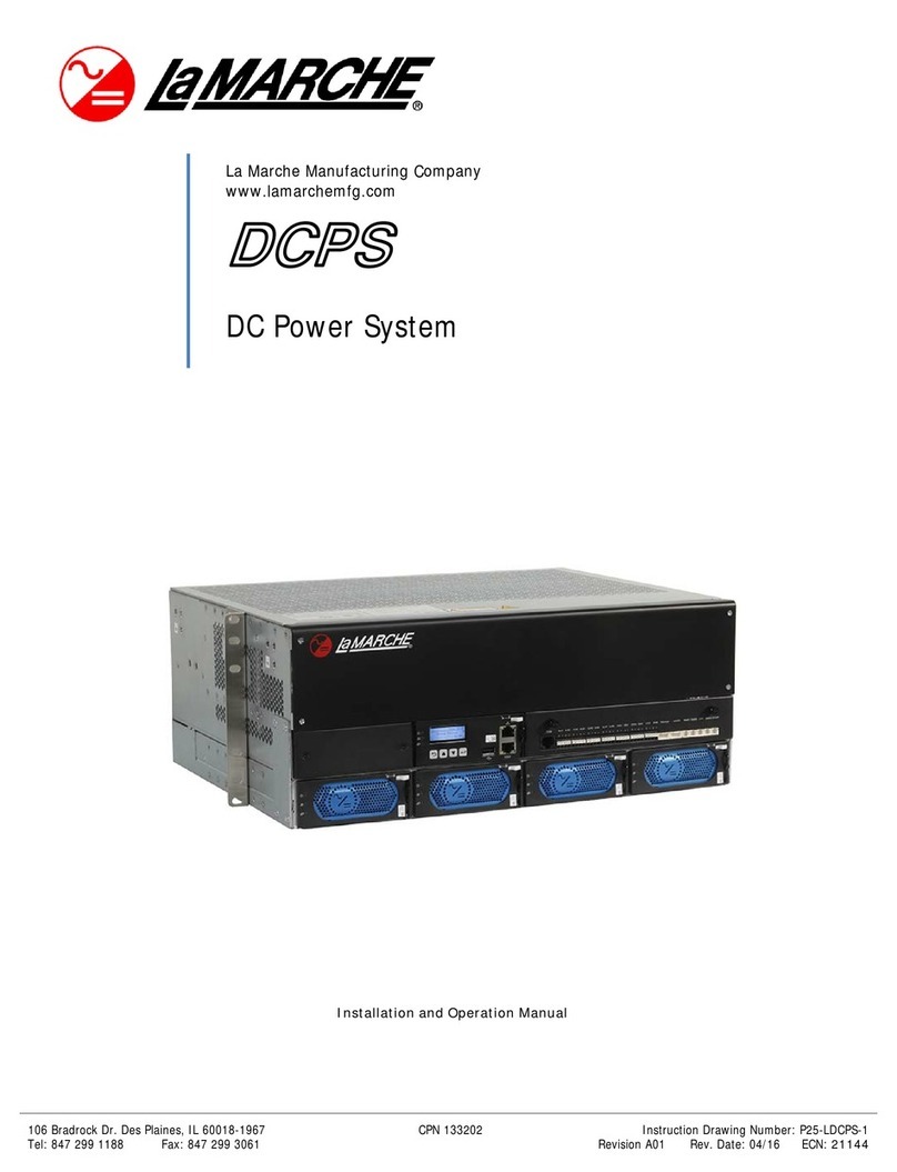
La Marche Manufacturing Company
www.lamarchemfg.com
DCPS
DC Power System
Installation and Operation Man al

i
Important Safety Instructions
Before sing this eq ipment, read all man als and other doc ments related to this nit and other eq ipment
connected to this nit. Always have a copy of the nit’s man al on file nearby in a safe place; if a replacement
copy of a man al is needed, it can be fo nd at www.lamarchemfg.com.
Electrical Safety
WARNING
Hazardo s Voltages are present at the inp t of power systems. The o tp t from rectifiers
and from batteries may be low in voltage, b t can have a very high c rrent capacity that may ca se
severe or even fatal inj ry.
When working with any live battery or power system, follow these preca tions:
•Never work alone on any live power system, someone sho ld always be close eno gh to come to yo r aid
•Remove personal metal items s ch as rings, bracelets, necklaces, and watches.
•Wear complete eye protection (with side shields) and clothing protection.
•Always wear gloves and se ins lated hand tools.
WARNING
Lethal Voltages are present within the power system. Parts inside the nit may still be
energized even when the nit has been disconnected from the AC inp t power. Check with a meter
before proceeding. Do not to ch any nins lated parts.
•A licensed electrician sho ld be sed in the installation of any nit.
•Always disconnect the nit from the s pply, batteries, and loads before performing maintenance or cleaning.
•If the nit is hot-swappable, simply remove it from the shelf for any maintenance or cleaning.
•Always ass me that an electrical connection is live and check the connection relative to gro nd.
•Be s re that neither liq ids nor any wet material come in contact with any internal components.
•Do not operate this nit o tside the inp t and o tp t ratings listed on the nit nameplate.
•Do not se this nit for any p rpose not described in the operation man al.
Mechanical Safety
•This nit or parts of the nit may get very hot d ring normal operation, se care when working nearby.
•Do not expose eq ipment to rain or snow. Always install in a clean, dry location.
•Do not operate eq ipment if it has received a sharp blow, been dropped, or otherwise damaged in any way.
•Do not disassemble this nit. Incorrect re-assembly may res lt in a risk of electric shock or fire.
Battery Safety
WARNING
Follow all of the battery man fact rer’s safety recommendations when working with or
aro nd battery systems. DO NOT smoke or introd ce a spark or open flame in the vicinity of a battery.
Some batteries generate explosive gases d ring normal battery operation.
•To red ce risk of arc, connect and disconnect the battery only when the nit is off.
•If it is necessary to remove battery connections, always remove the gro nded terminal from the battery first.
•Remove personal metal items s ch as rings, bracelets, necklaces, and watches.
•Always wear r bber gloves, safety glasses, and a r bber lined vest/apron when working near a battery.
•Have plenty of fresh water and soap nearby in case the battery electrolyte contacts skin, clothing, or eyes.
•If the battery electrolyte contacts skin or clothing, wash immediately with soap and water.
•If the electrolyte enters the eye, immediately flood the eye with r nning cold water for at least ten (10) min tes
and seek medical attention immediately.
•Do not drop metal on a battery. A spark or short-circ it co ld occ r and co ld ca se an explosion.

ii
Unit Location
•Allow at least 6 inches of free air on all vented s rfaces for proper cooling
•Allow s fficient clearance to open the front panel for servicing.
•Do not operate this nit in a closed-in area or restrict ventilation in any way.
•Do not set any battery on top of this nit.
•Never allow battery electrolyte to drip on this nit when reading the specific gravity or filling the battery.
•Never place this nit directly above a standard flooded battery. Gases from the battery will corrode and damage
eq ipment.
•A sealed maintenance free or valve reg lated lead acid (VRLA) battery may be placed below this eq ipment.
Check for Damages
Prior to npacking the prod ct, note any damage to the shipping container and take pict res. Unpack the prod ct
and inspect the exterior and interior of prod ct for damage. If any damage is observed, take pict res and contact
the carrier immediately to file a damage claim. Contact La Marche for a Ret rn Material A thorization n mber to
have the nit sent back for eval ation and repair.
CAUTION
Fail re to properly file a claim for shipping damages, or provide a copy of the claim to La
Marche, may void warranty service for any physical damages reported for repair.
Returns for Service
Save the original shipping container. If the prod ct needs to be ret rned for service, it sho ld be packaged in its
original shipping container. If the original container is damaged/ navailable, make s re the prod ct is packed
with at least three inches of shock-absorbing material to prevent shipping damage.
La Marche is not responsible
for damage ca sed by improper packaging of ret rned prod cts.
Inspection Checklist
Enclos re exterior and interior is not marred or dented.
There are no visible damage components.
All internal components are sec re.
Printed circ it boards are firmly seated.
All hardware and connections are tight.
All wire terminations are sec re.
All items on packing list have been incl ded.
Handling
Eq ipment can be very heavy with neven distrib tion of weight. Use adeq ate manpower or eq ipment for
handling. Until the eq ipment is sec rely mo nted, care m st be sed to prevent eq ipment from being accidently
tipped over or dropped.

iii
Table of Contents
Important Safety Instr ctions ........................................................................................................................ i
Electrical Safety ......................................................................................................................................... i
Mechanical Safety ...................................................................................................................................... i
Battery Safety ........................................................................................................................................... i
Unit Location ............................................................................................................................................. ii
Check for Damages ................................................................................................................................... ii
Ret rns for Service .................................................................................................................................... ii
Inspection Checklist ................................................................................................................................... ii
Handling ................................................................................................................................................... ii
Table of Contents ........................................................................................................................................ iii
1
Overview .............................................................................................................................................. 1
1.1
Introd ction .............................................................................................................................. 1
1.2
Model N mber Description ......................................................................................................... 1
1.3
Feat res ................................................................................................................................... 1
1.4
Work Principles ......................................................................................................................... 1
1.5
Config rations ........................................................................................................................... 2
2
Components ......................................................................................................................................... 2
2.1
Appearance ............................................................................................................................... 2
2.2
DCD – DC Distrib tion Panel ...................................................................................................... 2
2.3
DCR – Rectifier .......................................................................................................................... 3
2.4
DCSC – System Controller .......................................................................................................... 5
2.5
DCU – User Interface Mod le ..................................................................................................... 7
3
Installation ..........................................................................................................................................10
3.1
Installation Preparations ...........................................................................................................10
3.1.1
Tools ................................................................................................................................10
3.1.2
Req irements for Cable Ro ting .........................................................................................10
3.1.3
Unpacking and Acceptance ................................................................................................11
3.2
Installing the S brack ...............................................................................................................11
3.2.1
Installing the S brack into a 19-Inch Rack ..........................................................................11
3.2.2
Installing S brack into a 23-Inch Rack ................................................................................12
3.3
Installing Components ..............................................................................................................13
3.3.1
Installing Rectifier .............................................................................................................13
3.3.2
Installing Circ it Breaker ....................................................................................................13
3.4
Installing a Gro nd Cable ..........................................................................................................15
3.5
(Optional) Installing Dry Contact Signal Cables ...........................................................................15
3.6
Installing Comm nication Cables ...............................................................................................16
3.7
Installing DC O tp t Power Cables ............................................................................................16
3.8
Installing Battery Cables ...........................................................................................................16
3.9
Reinstalling AC D al-Live Wire Inp t Power Cables .....................................................................17
3.9.1
Installing AC Inp t Gro nd Cable .......................................................................................17
3.9.2
Installing AC Inp t Power Cable .........................................................................................18
4
Verifying the Installation .......................................................................................................................21

iv
4.1
Checking Hardware Installation .................................................................................................21
4.2
Checking Electrical Connections .................................................................................................21
4.3
Checking Cable Installation .......................................................................................................21
5
Commissioning .....................................................................................................................................22
5.1
Connecting the AC Power S pply ...............................................................................................22
5.2
Setting the Display Lang age ....................................................................................................22
5.3
Setting the Date and Time ........................................................................................................22
5.4
Setting Battery Parameters .......................................................................................................22
5.5
(Optional) Setting the Hibernation Parameter .............................................................................23
5.6
Setting Comm nication Parameters ...........................................................................................23
5.6.1
Setting Parameters before Using the SNMP Management .....................................................23
5.7
Connecting the Battery S pply ..................................................................................................25
6
Maintenance ........................................................................................................................................26
6.1
Performing Ro tine Maintenance ...............................................................................................26
6.2
Tro bleshooting Proced re .......................................................................................................26
A
Technical Specifications ....................................................................................................................27
B
Electrical Concept al Diagram...........................................................................................................29
C
Associations Between Alarms and Dry Contacts on the DCU ...............................................................30
D
Acronyms and Abbreviations .............................................................................................................31
E
Smoke Sensor Accessory Safety Notification ......................................................................................32
Man fact rer’s Warranty ..........................................................................................................................33
Doc ment Control and Revision History ........................................................................................................34
Table of Figures
Fig re 1 – Concept al Diagram ..................................................................................................................... 1
Fig re 2 – DCPS Front View .......................................................................................................................... 2
Fig re 3 – DCPS Top View ............................................................................................................................ 2
Fig re 4 – DCPS Back View .......................................................................................................................... 3
Fig re 5 – DCR (Rectifier) ............................................................................................................................ 3
Fig re 6 – DCR Panel ................................................................................................................................... 4
Fig re 7 – DCSC (System Controller) ............................................................................................................. 5
Fig re 8 – DCSC Panel ................................................................................................................................. 5
Fig re 9 – RS485/RS232 Port and FE Port Pino t ........................................................................................... 6
Fig re 10 – DCU Panel ................................................................................................................................. 7
Fig re 11 – DCU Pin N mbers ...................................................................................................................... 9
Fig re 12 – Installation Tools ......................................................................................................................10
Fig re 13 – Installing Mo nting Brackets (Normal Installation) ......................................................................11
Fig re 14 – Installing Mo nting Brackets (Reverse Installation) .....................................................................12
Fig re 15 – Installing the S brack ................................................................................................................12
Fig re 16 – Installing a Rectifier ..................................................................................................................13
Fig re 17 – Removing the Front Panel from the DCPS ...................................................................................13
Fig re 18 – Removing the Top Cover ...........................................................................................................14
Fig re 19 – Removing the Top Cover ...........................................................................................................14
Fig re 20 – Removing the Top Cover ...........................................................................................................14
Fig re 21 – S brack Gro nd Terminals .........................................................................................................15
Fig re 22 – Installing a Dry Contact Signal Cable ..........................................................................................15
Fig re 23 – Installing DC Power O tp t Cables .............................................................................................16
Fig re 24 – Installing Battery Cables ............................................................................................................17
Fig re 25 – Removing the Rear Cover from the DCPS ...................................................................................17

v
Fig re 26 – Removing the AC Protective Cover .............................................................................................18
Fig re 27 – AC Inp t Gro nd Terminals (Straight Rear View).........................................................................18
Fig re 28 – Installing Power Cables for fo r AC d al-live Wire Inp ts .............................................................19
Fig re 29 – Installing Power Cables for three AC d al-live Wire Inp ts ...........................................................19
Fig re 30 – Installing Power Cables for two AC d al-live Wire Inp ts .............................................................20
Fig re 31 – Installing Power Cables for one AC d al-live Wire Inp ts .............................................................21
Fig re 32 – Login Page ...............................................................................................................................24
Fig re 33 – Setting SNMPv1 and SNMPv2c Parameters..................................................................................24
Fig re 34 – Setting SNMPv3 Parameters .......................................................................................................25
Fig re 35 – DCPS Electrical Concept al Diagram ...........................................................................................29
Table 1 – Power Distrib tion Specifications .................................................................................................... 3
Table 2 – DCR Indicators.............................................................................................................................. 4
Table 3 – DCSC Indicators ............................................................................................................................ 5
Table 4 – DCSC B ttons ............................................................................................................................... 6
Table 5 – Comm nication Ports .................................................................................................................... 6
Table 6 – FE Port Pin Definitions ................................................................................................................... 7
Table 7 – RS485/RS232 Port Pin Definitions .................................................................................................. 7
Table 8 – DCU Ports ..................................................................................................................................... 8
Table 9 – Pin Definitions............................................................................................................................... 9
Table 10 – R les For Installing Mo nting Brackets ........................................................................................11
Table 11 – Setting the Date and Time ..........................................................................................................22
Table 12 – Setting Battery Parameters .........................................................................................................23
Table 13 – Setting the Hibernation Parameter ..............................................................................................23
Table 14 – IP Parameters ............................................................................................................................23
Table 15 – Technical Specifications ..............................................................................................................29
Table 16 – Associations Between Alarms and Dry Contacts ............................................................................30

1
1 Overview
1.1 Introduction
The La Marche DCPS system tilizes high efficiency rectifiers, a highly intelligent system controller, I/O interface
board for alarms/ sensors, and a load/battery distrib tion panel. This complete DC system offers battery
management with low voltage disconnect, remote monitoring, remote config ration and config rable alarm
contacts.
The compact design of the system red ces space req irements and installation cost. The system is config red
with 48V/50A high efficiency rectifiers to provide a rated o tp t c rrent p to 200A. The DC distrib tion section
is comprised of 16 pl ggable load breakers and 2 battery breakers.
1.2 Model Number Description
DCPS stands for DC Power System
1.3 Features
The DCPS has the following feat res:
Wide voltage range of 85VAC to 300VAC
Comprehensive battery management
Network application over a fast Ethernet (FE) port and an RS485/RS232 port
Comm nication s ch as the Simple Network Management Protocol (SNMP) and Hypertext Transfer
Protocol Sec re (HTTPS) to enable remote management and nattended working
Remote software pgrade
Liq id crystal display (LCD) for display and operations
Web ser interface (Web UI) for display and operations
Display in m ltiple optional lang ages
Hot-swappable DCR rectifiers and DCSC controller
Rectifier power factor p to 0.99
1.4 Work Principles
AC power enters rectifiers thro gh the AC inp ts of the DCD distrib tion panel. The rectifiers convert the AC inp t
into –48VDC o tp t, which is directed by the DC distrib tion to DC loads along different ro tes.
When the AC power is normal, rectifiers power DC loads and charge batteries. When the AC power is absent,
rectifiers stop working and batteries start to power loads. After the AC power res mes, rectifiers power DC loads
and charge batteries again.
The DCSC controller monitors the operating stat s of each component in the power system in real time and
performs appropriate intelligent control. When detecting a fa lt, the DCSC generates an alarm.
Figure 1 – Conceptual Diagram

2
1.5 Configurations
The s brack has 1U space for installing DCR rectifiers and 3U space for installing power distrib tion components
(incl ding 1U space for installing the DCSC controller).
2 Components
2.1 Appearance
Figure 2 – DCPS Front View
(1) DCD – DC Distrib tion Panel (2) DCSC – DC System Controller (3) DCU – DC User Interface Mod le
(4) DCR – DC Rectifiers
2.2 DCD – DC Distribution Panel
Fig re 3 shows the DC section of the DC distrib tion panel (top view witho t the top cover) for the DCPS. Fig re
4 shows the AC section of the DC distrib tion panel for the DCPS. Table 2 lists the power distrib tion specifications
for the DCPS.
Figure 3 – DCPS Top View
(1) RTN+ b sbar (2) DC O tp t Terminals (3) Battery Terminals

3
Figure 4 – DCPS Back View
(1) Cable Entry Holes (2) AC Inp t Gro nd Terminals (3) AC Inp t Terminals
Item DCPS
Inp t System 110 VAC d al–live wire
AC Inp t Fo r terminals (for one to fo r ro tes)
DC O tp t Circ it Breaker 16 BLVD circ it breakers (1A to 100A, depending on
c stomer req irements)
BLVD is short for Battery Low Voltage Disconnection.
DC S rge Protection Differential Mode: 10 kA; Common Mode: 20 kA
Battery Circ it Breaker Two circ it breakers (200A max, depending on c stomer
req irements)
Table 1 – Power Distribution Specifications
2.3 DCR – Rectifier
Description
The DCR50 rectifier converts AC power to DC power and tilizes high performance feat res, s ch as high efficiency
(>96%), high power density, walk-in start, complete protection and low noise. The o tp t voltage of the rectifiers
can be adj sted thro gh the DCSC controller. The rectifier is hot swappable, providing easy installation and
maintenance.
Figure 5 – DCR (Rectifier)

4
Panel
Figure 6 – DCR Panel
(1) Power Indicator (2) Alarm Indicator (3) Fa lt Indicator
(4) Locking Latch (5) Handle
Indicators
Indicator Color Status Description
Power Indicator Green Steady On The rectifier has an AC power inp t.
Off The rectifier has no AC power inp t.
The rectifier is fa lty.
Blinking at 0.5 Hz The rectifier is being q eried.
Blinking at 4 Hz The rectifier is loading an application
program.
Alarm Indicator Yellow Off No alarm is generated.
Steady On The rectifier generates an alarm for
power limiting d e to ambient
overtemperat re.
The rectifier generates an alarm for
sh tdown d e to ambient over-
temperat re or nder-temperat re.
The rectifier protects against AC
inp t overvoltage or nder-voltage.
The rectifier is hibernating.
Blinking at 0.5 Hz The comm nication between the
rectifier and the DCSC is interr pted.
Fa lt Indicator Red Off The rectifier is r nning properly.
Steady On The rectifier locks o t d e to o tp t
overvoltage.
The rectifier has no o tp t d e to an
internal fa lt.
Table 2 – DCR Indicators

5
2.4 DCSC – System Controller
Description
The DC System Controller (DCSC) is an intelligent mod le that monitors and manages La Marche DC power
systems. The controller provides the system with Battery Management, Energy Conservation, Rectifier
Management, Intelligent Battery Hibernation Mode, Battery Testing, Battery Charging, and C rrent Limiting
controls. System config ration settings and real-time parameters can be accessed either locally (thro gh a two-
line LCD display), or remotely (thro gh a Web User Interface).
Figure 7 – DCSC (System Controller)
Panel
Figure 8 – DCSC Panel
(1) R n Indicator (2) Minor Alarm Indicator (3) Major Alarm Indicator (4) B ttons
(5) USB Port (Reserved) (6) RS485/RS232 Port (7) Handle (8) Locking Latch
(9) FE Port (10) LCD Screen
Indicators
Name Color Status Description
R n Indicator
Green Off The DCSC is fa lty or has no DC inp t.
Blinking at 0.5 Hz The DCSC is r nning properly and
comm nicating with the host properly.
Blinking at 4 Hz The DCSC is r nning properly b t is not
comm nicating with the host properly.
Minor Alarm
Indicator
Yellow Off The DCSC does not generate any minor alarms.
Steady On The DCSC generates a minor alarm.
Major Alarm
Indicator
Red Off No critical or major alarm is generated.
Steady On A critical or major alarm is generated.
Table 3 – DCSC Indicators

6
Buttons
Button Name Description
Up Scrolls p men s or sets parameter val es.
Down Scrolls down men s or sets parameter val es.
Back Ret rns to the previo s men witho t saving the settings.
Enter
Enters the main men from the standby screen.
Enters a s bmen from the main men .
Saves the men settings.
The LCD screen becomes dark if no b tton is pressed within 30 seconds.
Yo need to log in again if no b tton is pressed within 1 min te.
The preset password is 000001 (refer to section 5.6 for accessing the controller via internet
browser)
Table 4 – DCSC Buttons
Communications Ports
Communications Port Communications Parameter
Communications Protocol
FE Port 10/100M A to-Adaptation HTTPS and SNMP
RS485/RS232 Port Ba d Rate: 9600 bit/s Master/Slave Protocols
All these ports are protected by a sec rity mechanism.
Table 5 – Communication Ports
Figure 9 – RS485/RS232 Port and FE Port Pinout

7
Pin Signal Description
1 TX+ Sends data over the FE.
2 TX-
3 RX+ Receives data over the FE.
6 RX-
4, 5, 7, and 8 Not defined None
Table 6 – FE Port Pin Definitions
Pin Signal Description
1 TX+ Sends data over RS485.
2 TX-
4 RX+ Receives data over RS485.
5 RX-
3 RX232 Receives data over RS232.
7 TX232 Sends data over RS232.
6 PGND Connects to the gro nd.
8 Not defined None
Table 7 – RS485/RS232 Port Pin Definitions
2.5 DCU – User Interface Module
Description
Eq ipped with the I/O mod le (DCU), the controller s pports config rable digital inp ts, alarm dry-contacts and
site sensor ports for environment management and alarms reporting. The DCU ser interface mod le provides
the ability to add m ltiple sensors for: ambient temperat re, h midity, water, door stat s, smoke and battery
temperat re. The dry contact alarms are config rable and can be c stomized pon the DC system’s req irements.
All alarms can be easily config red and monitored remotely thro gh the WebUI (Web User Interface).
Figure 10 – DCU Panel

8
Ports
Port Type Silk Screen Description
Sensor Port TEM-HUM Temperat re and H midity Sensor
WATER Water Sensor
TEMP1 Ambient Temperat re Sensor 1
TEMP2 Ambient Temperat re Sensor 2
GATE Door Stat s Sensor
SMOKE Smoke Sensor (Refer to Appendix E)
BTEMP Battery Temperat re Sensor
Boolean Val e Signal Port
For the associations
between the Boolean
val e signal ports and
alarms, see the appendix.
DIN1 Boolean Val e Inp t 1
DIN2 Boolean Val e Inp t 2
DIN3 Boolean Val e Inp t 3
DIN4 Boolean Val e Inp t 4
DIN5 Boolean Val e Inp t 5
DIN6 Boolean Val e Inp t 6
Dry Contact
For the associations
between the dry contacts
and alarms, see the
appendix.
ALM1 Dry Contact O tp t 1
ALM2 Dry Contact O tp t 2
ALM3 Dry Contact O tp t 3
ALM4 Dry Contact O tp t 4
ALM5 Dry Contact O tp t 5
ALM6 Dry Contact O tp t 6
ALM7 Dry Contact O tp t 7
ALM8 Dry Contact O tp t 8
Comm nications Port COM RS485 Port
Table 8 – DCU Ports

9
Pins
Figure 11 – DCU Pin Numbers
Silkscreen No. Pin Definition
TEM-HUM 1 12V
2 ENV_TEMP
3 12V
4 ENV_HUM
WATER 1 12V
2 WATER
3 GND
4 Not defined
TEMP1 1 TEMP1
2 GND
TEMP2 1 TEMP2
2 GND
GATE 1 DIN7+
2 JTD7
SMOKE 1 12V
2 SMOKE
BTEMP 1 BTEM1
2 GND
Table 9 – Pin Definitions

10
3 Installation
3.1 Installation Preparations
3.1.1 Tools
Figure 12 – Installation Tools
3.1.2 Req irements for Cable Ro ting
The bending semidiameter of power cables and gro nd cables sho ld be greater than or eq al to three
times the diameter of the power cables and gro nd cables respectively.
The bending semidiameter of signal cables sho ld be greater than or eq al to five times the diameter of
the signal cables.
Cables of the same type sho ld be bo nd together. Cables of different types sho ld keep a minim m
distance of 30 mm from each other to avoid tangles.
Cables that are bo nd together sho ld be close to each other, neat, and free of damage.
The protection gro nd cables m st not be bo nd to or tangled with the signal cables. An appropriate
distance sho ld be left between them to minimize interr ption.
AC power cables, DC power cables, signal cables, and comm nications cables m st be bo nd
separately.
Power cables m st be ro ted straightly. No joint or weld can be fo nd in a power cable. In case of
ins fficient cable length, se a longer cable.

11
3.1.3 Unpacking and Acceptance
Proced re
Step 1
Unpack the s brack.
Step 2
Check the total q antity of eq ipment against the packing list attached to each packing case. If
the total q antity is inconsistent with the packing list, identify the ca se and contact the La
Marche office.
Step 3
Check whether the packing case is intact. If no, identify the ca se and contact the La Marche
office.
3.2 Installing the Subrack
Rack Type U-Shaped Slot Inward U-Shaped Slot Outward
19-inch rack Normal installation
(three mo nting holes)
Reverse installation
(three mo nting holes)
23-inch rack Normal installation
(three mo nting holes)
Normal installation
(three mo nting holes)
Table 10 – Rules For Installing Mounting Brackets
3.2.1 Installing the S brack into a 19-Inch Rack
Proced re
Step 1
Install mo nting brackets onto the s brack.
Figure 13 – Installing Mounting Brackets (Normal Installation)
(1) Mo nting Hole 1
(Reserved)
(2) Mo nting Hole 2
(Reserved, defa lt)
(3) Mo nting Hole 3
(Reserved)
Step 2
Install the s brack into a 19-inch rack.

12
Figure 14 – Installing Mounting Brackets (Reverse Installation)
(1) Mo nting Hole 1
(Reserved)
(2) Mo nting Hole 2
(Reserved, defa lt)
(3) Mo nting Hole 3
(Reserved)
Figure 15 – Installing the Subrack
3.2.2 Installing S brack into a 23-Inch Rack
For details abo t how to install the s brack into a 23-inch rack, see section 3.2.1.

13
3.3 Installing Components
3.3.1 Installing Rectifier
Prereq isites
Rectifiers are fo nd intact after npacking and check. In case of any discrepancy, contact the La
Marche office.
The filler panels on the slot for installing the rectifiers have been removed from the cabinet.
Proced re
Step 1
P sh the locking latch towards the left.
Step 2
Draw the handle downwards.
Step 3
Gently p sh a rectifier into its slot along the g ide rail.
Step 4
P sh the handle pwards.
Step 5
P sh the locking latch towards the right to sec re the handle.
Figure 16 – Installing a Rectifier
3.3.2 Installing Circ it Breaker
Proced re
Step 1
Remove the front panel from the DCPS, as shown in Fig re 17
Figure 17 – Removing the Front Panel from the DCPS
Step 2
Remove the top cover from the DCPS.
1.
Loosen the captive screws on the top cover by sing a Philips screw driver.
2.
P ll the top cover forward to the locking position.

14
Figure 18 – Removing the Top Cover
Step 3
Lift the top cover and take it o t.
Figure 19 – Removing the Top Cover
CAUTION
When yo remove the top cover, hold the top cover by hands to prevent it from falling into
the s brack.
Step 4
Switch off the circ it breaker.
Step 5
Insert the circ it breaker into the mo nting holes and p sh the circ it breaker forward ntil it is
in position, as shown in Fig re 20.
Figure 20 – Removing the Top Cover
Other manuals for DCPS
1
Table of contents
Other Lamarche Power Supply manuals