LAMBORGHINI JEREZ ECO User manual
Other LAMBORGHINI Boiler manuals
LAMBORGHINI
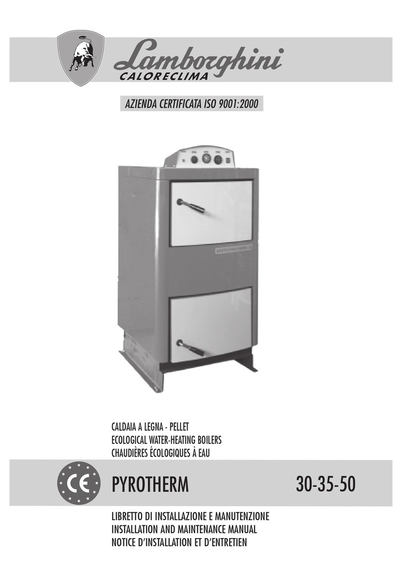
LAMBORGHINI PYROTHERM 30 Manual
LAMBORGHINI
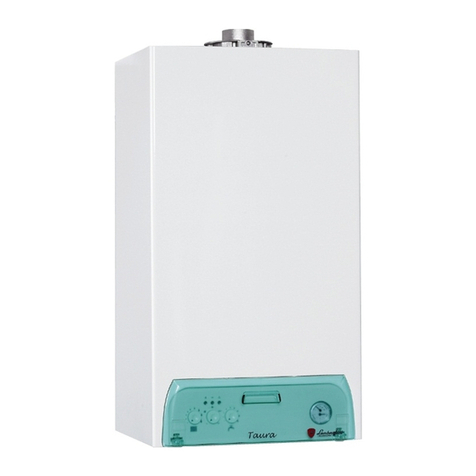
LAMBORGHINI Taura 24 MCS W TOP User manual
LAMBORGHINI
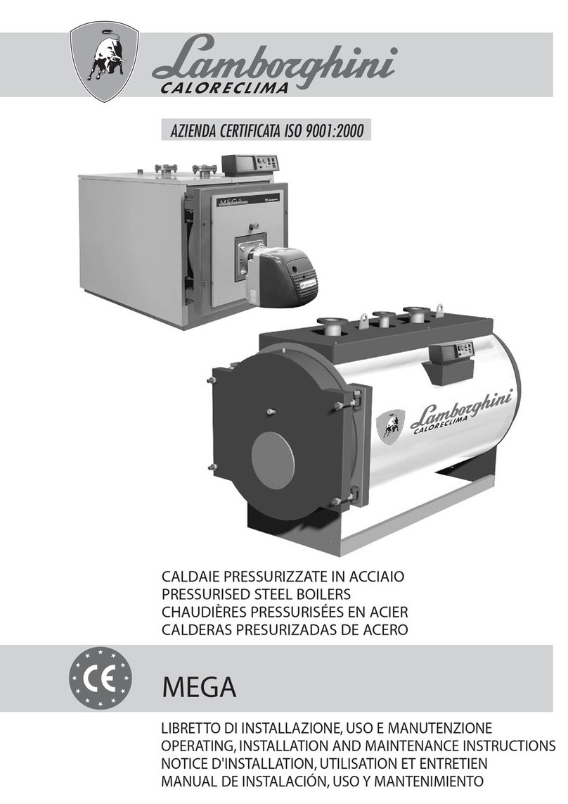
LAMBORGHINI MEGA 92 User manual
LAMBORGHINI
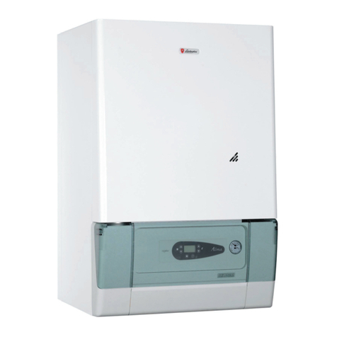
LAMBORGHINI ALMA 24 MBS W TOP Manual

LAMBORGHINI
LAMBORGHINI Xilo D 20 MC W TOP U/IT User manual
LAMBORGHINI
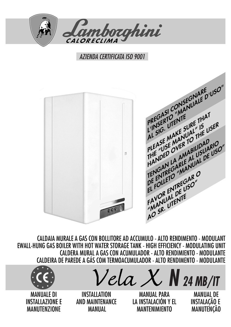
LAMBORGHINI Vela XN 24 MB/IT Manual
LAMBORGHINI
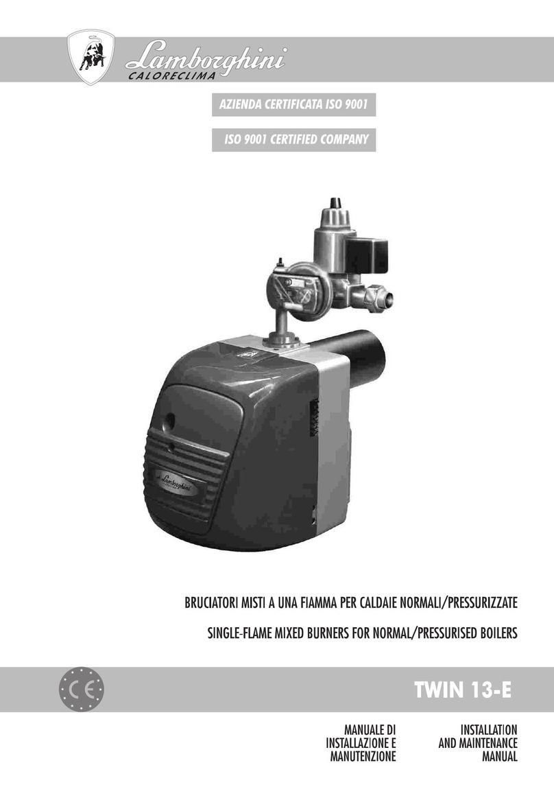
LAMBORGHINI TWIN 13-E Manual
LAMBORGHINI
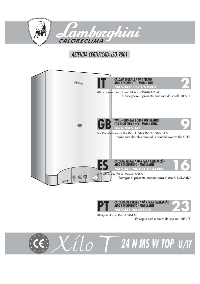
LAMBORGHINI Xilo T 24 N MS W TOP U/IT User manual

LAMBORGHINI
LAMBORGHINI ERA MD Troubleshooting guide
LAMBORGHINI
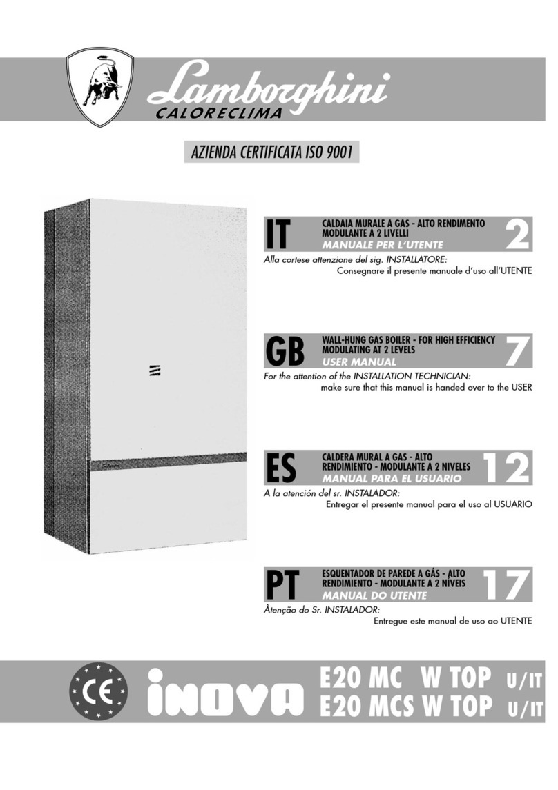
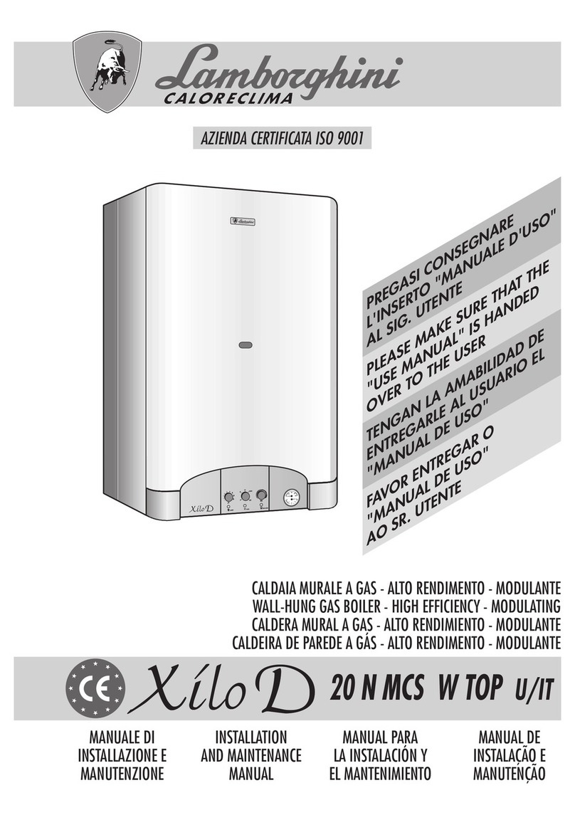
LAMBORGHINI Inova E20 MC W TOP User manual
LAMBORGHINI
LAMBORGHINI XILO D Manual
LAMBORGHINI
LAMBORGHINI INOVA L 20 MC TOP - SCHEMA Manual
LAMBORGHINI
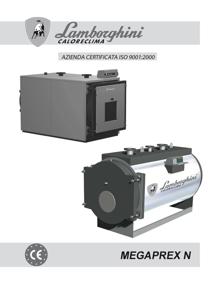
LAMBORGHINI MEGAPREX N 92 Operating instructions
LAMBORGHINI
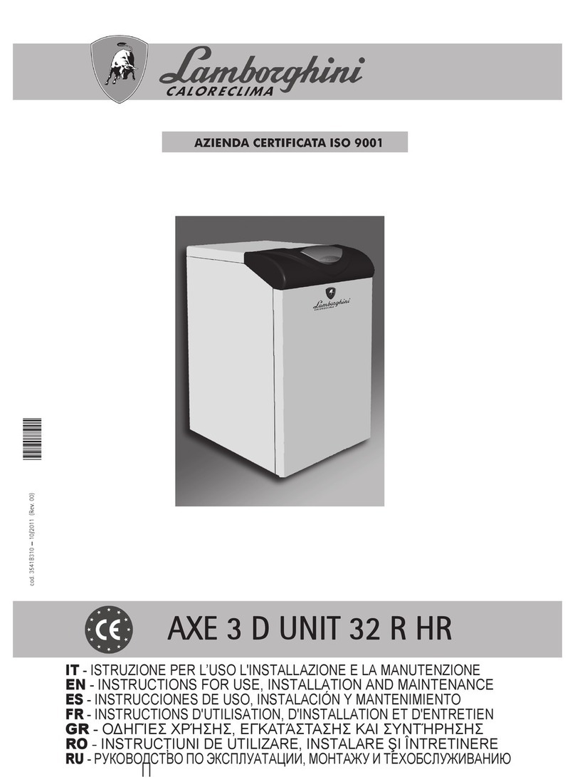
LAMBORGHINI AXE 3 D UNIT 32 R HR User manual
LAMBORGHINI
LAMBORGHINI thin 24 MCS W TOP U/IT Manual
LAMBORGHINI
LAMBORGHINI EL-DB EVO N 32 Troubleshooting guide
Popular Boiler manuals by other brands

Vaillant
Vaillant uniSTOR VIH SW GB 500 BES operating instructions

Radijator
Radijator BIO max 23.1 instruction manual

Brunner
Brunner BSV 20 Instructions for use

Buderus
Buderus Logamax GB062-24 KDE H V2 Service manual

Potterton
Potterton 50e Installation and Servicing Manual

UTICA BOILERS
UTICA BOILERS TriFire Assembly instructions

Joannes
Joannes LADY Series Installation and maintenance manual

ECR International
ECR International UB90-125 Installation, operation & maintenance manual

Froling
Froling P4 Pellet 8 - 105 installation instructions

Froling
Froling FHG Turbo 3000 operating instructions

U.S. Boiler Company
U.S. Boiler Company K2 operating instructions

Henrad
Henrad C95 FF user guide

NeOvo
NeOvo EcoNox EF 36 user guide

Potterton
Potterton PROMAX SL 12 user guide

Eco Hometec
Eco Hometec EC 25 COMPACT Technical manual

Viessmann
Viessmann VITODENS 200 Operating instructions and user's information manual

Baxi
Baxi Prime 1.24 installation manual

REXNOVA
REXNOVA ISA 20 BITHERMAL Installation, use and maintenance manual


