Lamona TAP6000 User manual

TAP6000
–
3 in 1 Hot Tap
04-17
Guarantee (UK only):
Your tap has the benefit of a comprehensive manufacturer’s guarantee, details of which are shown on your
Proof of Purchase Document. Any claim during the period of the guarantee must be accompanied by the Proof
of Purchase. The product must be correctly installed and operated in accordance with the manufacturer’s
instructions and used for normal domestic purposes. This guarantee does not cover accidental damage,
misuse or alterations which are likely to affect the product. The guarantee is invalid if the product is tampered
with, or repaired by any unauthori ed person. The guarantee in no way affects your statutory or legal rights.
Care nstructions for your Kitchen Sink Mixer:
To maintain the appearance of this tap, ensure that it is regularly cleaned only using a clean, soft damp cloth.
A solution of warm water and a mild liquid detergent may be used where necessary, and then the fitting rinsed
thoroughly and wiped dry. Any other cleaning action will invalidate your warranty.
Abrasive cleaners, scouring cleaners and acidic cleaners must not be used under any circumstances. Avoid
contact with all solvents (including chlorinated solvents, ketones or acetones as these may result in surface
deterioration or etching). Also avoid contact with any harsh household chemicals such as oven cleaners, drain
cleaners, rust removers, paint strippers and toilet bowl cleaners, bar keepers friend or Brasso.
Where the tap has a removable aerator on the spout exit it can be removed and cleaned periodically to
maintain optimum flow performance.
mportant Technical Data:
Minimum operating pressure (hot): 0.75 bar Minimum operating pressure (cold): 2.5 bar (with filter) /
1.0 bar (without filter)
Maximum operating pressure: 5.5 bar* Maximum domestic hot water temperature: 70°C*
Flow characteristics: Domestic Hot & Cold
share outer single flow spout.
Boiled water: Through centre spout channel.
Recommended domestic hot water temperature: 46°C
*If these temperatures or pressures are exceeded, even for short periods, damage can result. In these
instances a thermostatic mixing or pressure reducing valve should be installed.
This product is manufactured in accordance with recognised European standards. Please ensure that your
kitchen mixer is fitted in accordance with Local Water Byelaws. Where hot and cold water mix within the
tap, then suitable non return (check) valves should be installed to both the hot and cold supplies to
prevent backflow, a preinstalled non return valve on the cold supply flexi hose (B1) is already supplied (see
instructions key).
Hot and cold supply pressures should be as closely balanced as possible for best results. Supply pipes should
maintain the maximum diameter until immediately before the fitting. The differential between the hot and cold
water supply temperatures should be sufficient to allow correct mixing function.
These installation guidelines have been prepared for your direction and you must exercise due care at all
times. We do not accept responsibility for problems that may occur through improper installation. Whilst
assembling the tap take care not to accidentally loosen any factory fixed assemblies.
This tap has been 100% assembly tested; therefore you may expect a small residual amount of water to
remain in the tap when delivered. Any water marks can be removed using the above care advice.

nstallation Preparation
⚠
Before installing the new mixer it is essential that you thoroughly flush through the supply pipes in order to
remove any remaining solder, swarf or impurities from your system. Failure to carry out this simple procedure
could cause problems or damage to the workings of the mixertap or boiler.
We recommend installing particle filters (not shown) and isolation valves (B5) to both the hot and cold feed pipes
in an accessible position. This will help to prevent premature failure of the valves and ease any future
maintenance.
Ensure you have suitable domestic hot and cold water pressure before installing this product (see technical data
for more information).
All parts should be removed from their packaging and inspected for any transport damage and that all parts are present
prior to installation.
Shut off your water heating system and ensure that your mains stopcock is closed. Open the lowest hot and cold taps in
the house and allow the water to run until fully stopped.
If replacing an existing tap, remove the tap & clean the end of the feed pipes using wire wool, the tap hole area should be
free from dirt and sealant. Loosely position the tap and tail pipes to check if any alteration to the existing pipework is
required, if this is the case do this now.

Parts and Contents
Key Description Qty Supplied
A1 Mixer tap 1
A2 Base plinth 1
A3 Base plinth seal 1
A4 Sink or worktop (max.
50mm) 0
A5 White triangular plate
(for steel sinks only) 1
A6 Lower gasket 1
A7 Metal horseshoe 1
A8 Fixing stud 1
A9 Fixing nut 1
B1
Domestic cold flexible
hose (including non-
return valve)
1
B2 15mm olive 0
B3 15mm nut 0
B4 15mm pipe 0
B5 15mm isolation valve 0
B6
Domestic hot flexible
hose (excluding non-
return valve)
1
C1
Cold out (to filter &
boiler) flexible hose
(including seal)
1
C2 3/8” M x ¼”F adaptor 1
C3 ¼” NPT M x ¼”
pushfit 1
C4 ¼” outside diameter
plastic pipe 1
*
C5 Filter bracket screw 1
C6 Filter bracket 1
C7 Filter cartridge 1
D1
110° rated hot water
hose (from boiler
output)
1
D2 3/8” fibre seal 1
E1 Boiler 1
*
E2 Flexible boiled water
output pipe 1
*
E3 Connecting tundish
assembly 1
*
E4 Flexible drain pipe 1
*
*
Part supplied with boiler pack,
For the boiler parts list and connections please
refer to the instructions supplied with the boiler
for more detail.
⚠ Do not switch on the
boiler until instructed.
To obtain replacement filter
cartridges
please call; 01226 283434 or visit;
www.filter-taps.co.uk/howdens.html

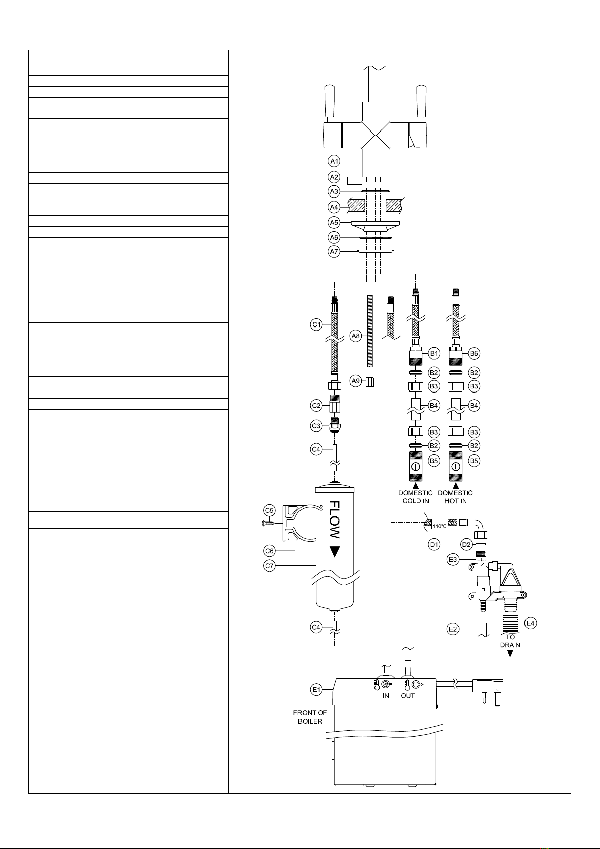
Tap & Filter installation
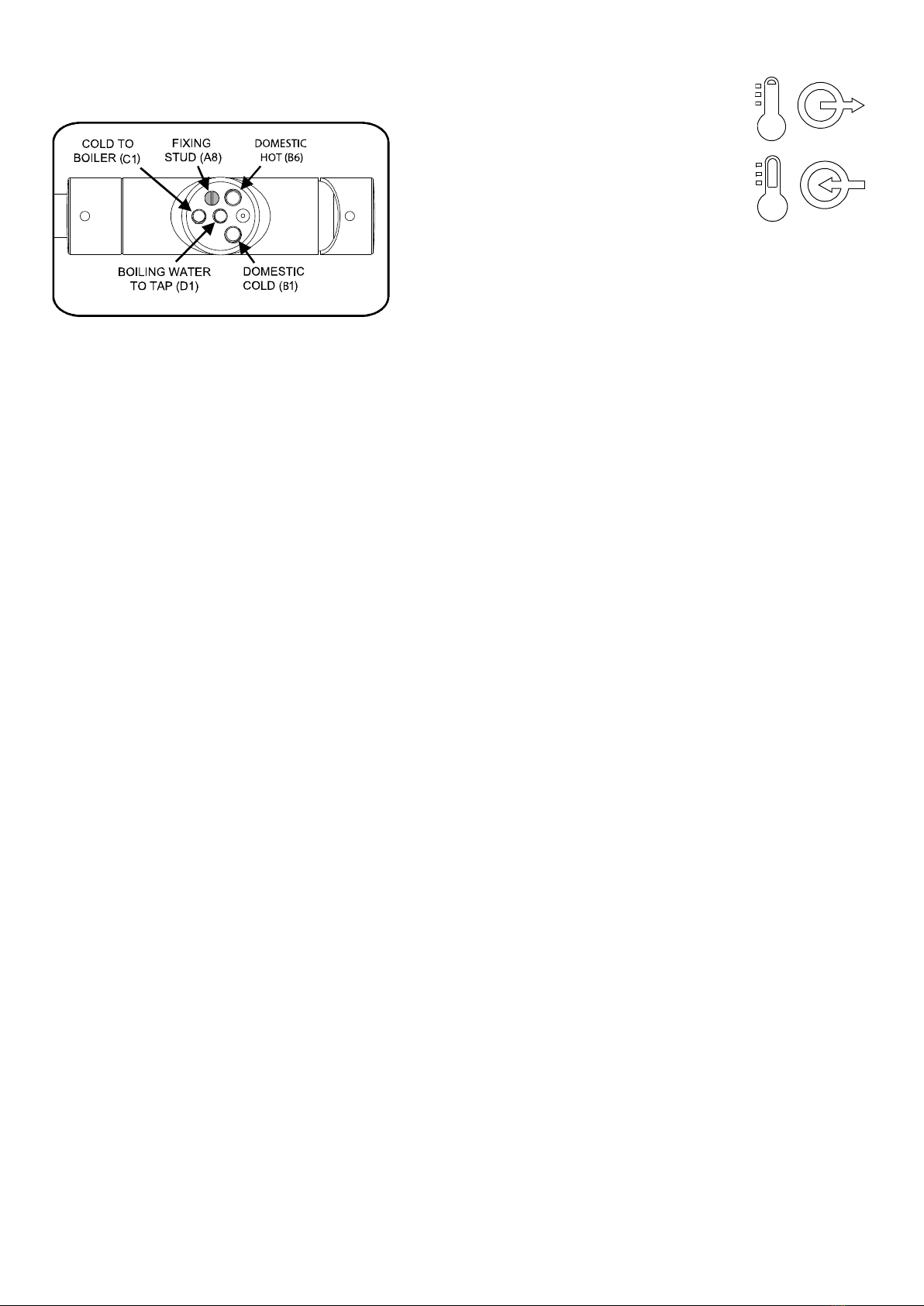
This diagram shows the view of the base of the tap (A1) with the
boiling water handle to the left of the body.
nstall the Tap:
This diagram
shows the
markings on
boiler (E1) to
indicate the inlet
and outlet, see
the boiler
instructions for
further detail.
boiler hot water outlet
boiler cold water inlet
1. Screw the fixing stud (A8) into the base of tap (A1) as shown on the diagram.
2. Place the base plinth (A2) and base plinth seal (A3) onto the base of the tap (A1).
3. Hand tighten the domestic hot flexi hose (B6) into the base of tap (A1) as shown in the diagram above.
4. Hand tighten the domestic cold flexi hose (B1) into the base of tap (A1) as shown in the diagram above.
5. Hand tighten the cold out flexi hose (C1) into the base of tap (A1) as shown in the diagram above.
6. Hand tighten the 110° rated hot flexi hose (D1) into the centre inlet as shown on the diagram and marked on the tap body.
7. Place the tap (A1-A3) centrally and straight to the tap hole, passing the fixing stud (A8), flexi hoses (B1, B6, C1, D1) through the
tap hole.
8. Pass the lower gasket (A6) then the metal horseshoe (A7) over the fixing stud (A8). Note: only if the tap is to be fitted to a
stainless steel sink then the white triangular plate (A5) can be fitted where shown to improve the stability of the tap.
9. Using an 13mm box spanner or small adjustable spanner tighten fixing nut (A9) onto the fixing stud (A8).
10. Screw pushfit (C3) into adaptor (C2), we recommend using PTFE tape (do not use sealing compound) on the thread of
pushfit (C3) to make a good seal without applying excessive force (which may damage the plastic pushfit if
overtightened).
11. Screw pushfit (C3) and adaptor (C2) into the cold out flexi hose (C1).
12. Connect the cold water flexi hose (B1) to the cold water isolation valve (B5) using a section of 15mm pipe (B4) and compression
nuts (B3) and olives (B2). Repeat the process to connect the domestic hot flexi hose (B6) to the domestic hot water supply.
nstall the Filter:
1. Find a suitable place to mount the filter cartridge (C7) under the sink, it must be mounted vertically as shown, easily accessible
(to be changed periodically), away from any heat source and close enough not to exceed the available length of the ¼” plastic
pipe (C4) supplied.
2. Using the self-tapping screw (C5) securely fix the filter bracket (C6) to the cabinet wall.
3. Write the installation date onto the filter label in permanent pen then clip the filter cartridge (C7) into the bracket (C6) as shown.
You must respect the direction of flow as indicated.
4. Measure and then cut required length of ¼” pipe (C4) to connect pushfit (C3) to the filter cartridge (C7) inlet, then from the filter
cartridge (C7) outlet to the boiler inlet (E1) leave a little additional length on both pipes to allow the filter cartridge (C7) to be
unclipped and replaced more easily by the customer. The ¼” pipe (C4) must be cut cleanly and squarely with a sharp tube snip.
5. Firmly push connect the ¼” pipe (C4) between pushfit (C3) and filter cartridge inlet (C7), repeat this from the filter cartridge (C7)
outlet to the boiler inlet (E1).
After installation of the tap and filter is complete
1. Please refer to ‘boiler installation and user guide’ for the next steps and complete the installation. Do not plug in the boiler until
advised.
2. Reconnect the domestic hot and cold water supplies then open isolation valves (B5). As the system starts to refill, check carefully
all new water connections for leaks. After the product installation is complete we recommend you recheck for any slower leaks.
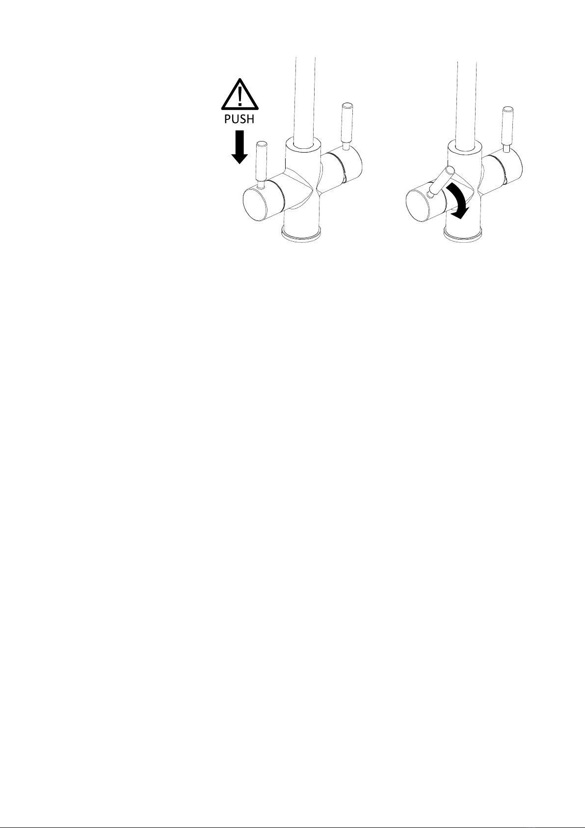
3. Turn on the hot water handle fully, keep the lever open until all air is expelled and cold (unboiled) water exits the centre channel
of the tap spout, flush a further 10 litres of cold (unboiled) water through the filter, boiler and tap. You may notice a discolouration
to the water at first, this is loose carbon fines from the optional filter it is normal, harmless and will pass with flushing. Once
complete turn off the left hand hot water handle.
4. Plug in and switch on the boiler, wait until the water has finished heating fully.
5. Clean the tap with a damp soft cloth and a mild dish soap to remove any grease marks created during installation as per the care
instructions.

Using the product
To dispense hot water:
Fully depress the left hand lever (fig 1.)
and then simultaneously turn the handle
forwards (fig 2.), the further forwards the
lever is turned the greater the flow.
At around 45° rotation is reached (fig 2.)
the maximum flow is achieved.
It is normal for the hot water to take a
moment to dispense as the water empties
from the product after each use, once the
handle is closed water will continue to run
until the spout has emptied.
Fig 1. Fig 2.
⚠
Should you see that hot water persistently drips from the centre channel of the tap spout (when the tap is not in use
and the boilers indicator red light is switched on) then you should reduce the temperature adjustment dial on the top of
the boiler, see the boiler user manual for further detail.
Each time the product is used you should flush a small amount of boiled water through before use, typically this can be
used to preheat your cup, if unused for extended periods then flush the product a longer time.
⚠
WARN NG: TH S APPL ANCE CAN BE USED BY CH LDREN AGED FROM 8 YEARS AND ABOVE
AND PERSONS W TH REDUCED PHYS CAL, SENSORY OR MENTAL CAPAB L T ES OR LACK OF
EXPER ENCE AND KNOWLEDGE ONLY F THEY HAVE BEEN G VEN SUPERV S ON OR NSTRUCT ON
CONCERN NG USE OF THE APPL ANCE N A SAFE WAY AND HAVE UNDERSTAND THE HAZARDS
NVOLVED. CH LDREN SHALL NOT PLAY W TH THE APPL ANCE. CLEAN NG AND USER
MA NTENANCE SHALL NOT BE MADE BY CH LDREN. ALL W R NG AND NSTALLAT ON MUST BE
SUPERV SED BY A SU TABLY QUAL F ED PERSON.
⚠
Do not add to, exchange or modify any component of the boiler or mixer tap, only genuine parts must be
used. The spout exit or any part of the system must not include any additional third party adaptors,
components or connections that will add resistance or modify the system.
⚠
The installation should be periodically checked for damage, if the property is left unattended for a
prolonged period we recommend isolating water supplies and switching off the boiler at the mains socket, on
reconnection flush thoroughly.
Please leave these instructions for your customer.
ref/tap6000v1
Table of contents
Popular Water Filtration System manuals by other brands

Hydro International
Hydro International Downstream Defender 4-FT Operation and maintenance manual

GE
GE FQROPF Instruction Manual and Data Sheet

Clean Water Systems
Clean Water Systems Tannin 5900e Series Installation & start?up guide

Hayward
Hayward HCF Series Installation and operation manual

VGE
VGE xclear MULTIMAX 5W manual

Krohn-Hite
Krohn-Hite 3320 Series Operating and maintenance manual