Lampert DENTA PUK User manual

OPERATING INSTRUCTIONS
“DENTA PUK”
Dear customer!
The manual that you hold in your hands is designed to acquaint you with the operating
principles and correct maintenance of your “DENTA PUK”.
Please read this manual carefully and clearly observe the guidelines it describes; this way
malfunctions and operating errors can be avoided. Adhering to the guidelines will promote
the working life of the machine and assure that it remains in constant operational
readiness during this time; it will also ensure your personal safety.
This device may only be operated by qualified personnel, and then only for its
designated use and in accordance with the guidelines contained in this manual. The
manufacturer accepts no responsibility, and is in no way liable for damage caused
by improper use or operation of the machine.
Before first using your “DENTA PUK”, please be sure to carefully read the manual
sections “General Safety Requirements” and “Personal safety”.
Please retain these instructions for future reference.
A note on conformity marks
The equipment made by “Lampert Werktechnik GmbH”, fulfils the conformity requirements
of CE certification and is manufactured according to VDE guidelines.
The DENTA PUK is certified as “BG-PRÜFZERT” by the German federation of statutory
accident insurance institutions for the industrial sector, and carries the “GS” safety
standards certification mark.
When overhauling or reconditioning our devices, we strongly advise to use original parts
only. Our customer service team is at your disposal, and will gladly assist in any way they
can.
The device may only be opened, or alterations carried out, by authorised customer
service technicians. Noncompliance will result in all warrantees and liability claims
becoming void.
LAMPERT WERKTECHNIK GMBH
October 2009

2
TABLE OF CONTENTS
SECTION
A
SAFETY NOTICES AND TERMINOLOGY USED 3
1
DESIGNATED USE 3
2
INTRODUCTION 3
3
SAFETY INSTRUCTIONS
3-1
General safety instructions 4
3-2
Personal safety and potential risks 5
4
INSTALLATION
4-1
Setup guidelines 5
4-2
Controls, functions and features -front 6
4-3
Controls, functions and features -back 7
4-4
Starting up 7-9
4-5
Changing language displayed 9
5
OPERATING PRINCIPLES AND SETTING THE PARAMETERS 9
5-1
Adjusting the welding parameters 10
5-2
Using the programmable memory 11
6
INSTRUCTIONS FOR USE
6-1
Welding instructions 12
6-2
Welding with the foot switch (optional accessory) 13
6-3
Working with the adapter cable for welding pins (Ø 1,3 mm) 14
6-4
Tips and general pointers 14
6-5
Sharpening the electrodes 15
6-6
Care and maintenance 15
7
TECHNICAL DATA
7-1
Technical information 16
7-2
Identification plate – explanation of picture symbols 16
8
TROUBLE SHOOTING 17
9
SPARE PARTS LIST 18
10
DISPOSAL INFORMATION 19
11
EG-CONFORMITY DECLARATION 19

3
A SAFETY NOTICES AND TERMINOLOGY USED
Warning!
“Warning!” Denotes a potentially dangerous situation. Failure to comply with these
notices can result in serious injury or even death.
Caution!
“Caution!” These notices show a situation that can result in minor injury or damage to
property if not complied with.
Please note!
“Please note!” Points out situations where ignoring the safety notice can negatively
affect the result of work being carried out and damage the equipment.
Important!
“Important!” Notices are helpful hints and other particularly useful pieces of information.
They do not indicate a potentially dangerous or harmful situation.
1 DESIGNATED USE
Applying welds to all common dental alloys and titanium, for work associated with the
repairing or manufacturing of dental appliances for patients. It is prohibited to use this
apparatus to carry out welds in or on the body.
Any other application of the appliance other than the above stated is prohibited.
It is prohibited to use this apparatus out of doors. Use only in dry surroundings!
No liability of any kind will be assumed for the durability of welds. We recommend
that welds are always inspected.
2 INTRODUCTION
The DENTA PUK is as an excellent way of bringing the technique of welding to a broad
band of users in the dental industry, whilst at the same time keeping running costs and
the initial outlay to a minimum.
Thanks to a clever combination of high performance electronics and precision
mechanics, we’ve been able to create a unique micro-welding device.
The DENTA PUK is small in size, low in weight and consumes only a minimum of
energy. These are not just important facts, but also very beneficial attributes. Its
excellent ignition and welding characteristics permit a broad spectrum of applications
and a wide range of uses.
By bringing new possibilities to the world of welding engineering, entirely new dimensions
are available to those producing or repairing dental appliances.

4
3 SAFETY INSTRUCTIONS
3-1 GENERAL SAFETY INSTRUCTIONS
The device may only be opened by a trained and qualified technician or electrician.
Before opening the device, remove the mains plug from the wall socket, and make sure
that the machine is not receiving any electrical current. Discharge any of the machines
components which contain and store an electrical charge.
Should any questions arise, please always consult a trained professional.
Our customer service team is naturally also always at your service; staffed with a
competent, professionally trained workforce, they have the necessary resources and
equipment at their disposal and would be pleased to assist you further wherever
necessary.
Always use original cables of sufficient length and make sure that the clamp holding the
work piece is properly and securely attached.
The risk of hazards may arise from welding current as well as from mains electricity.
When carrying out repair or servicing work, the machine must always be disconnected
from the power supply. Throughout any work of longer duration, that requires the
qualified person to leave (even if only briefly) the place where work is being carried out,
the wall socket must also be securely closed off.
The highest, and therefore most dangerous voltage in the welding circuit, is the open
circuit voltage. The maximum permissible open circuit voltage is laid down by national
and international regulations. This differs depending on the type of welding current, the
type of power source, and the potential for electrical hazard of the workplace.
If it can be assumed that a safe operation of the device is no longer possible, the
machine must be shut down and removed from the power supply; it must also be
secured against accidental re-operation or activation.
It is likely, and can be expected, that a safe operation of the device is no longer possible
when:
- The machine shows visible signs of damage.
- Malfunctions or faults occur.
- The machine will not operate.
Please observe the appropriate safety measures when handling gas bottles and the
safety rules in dealing with gases.
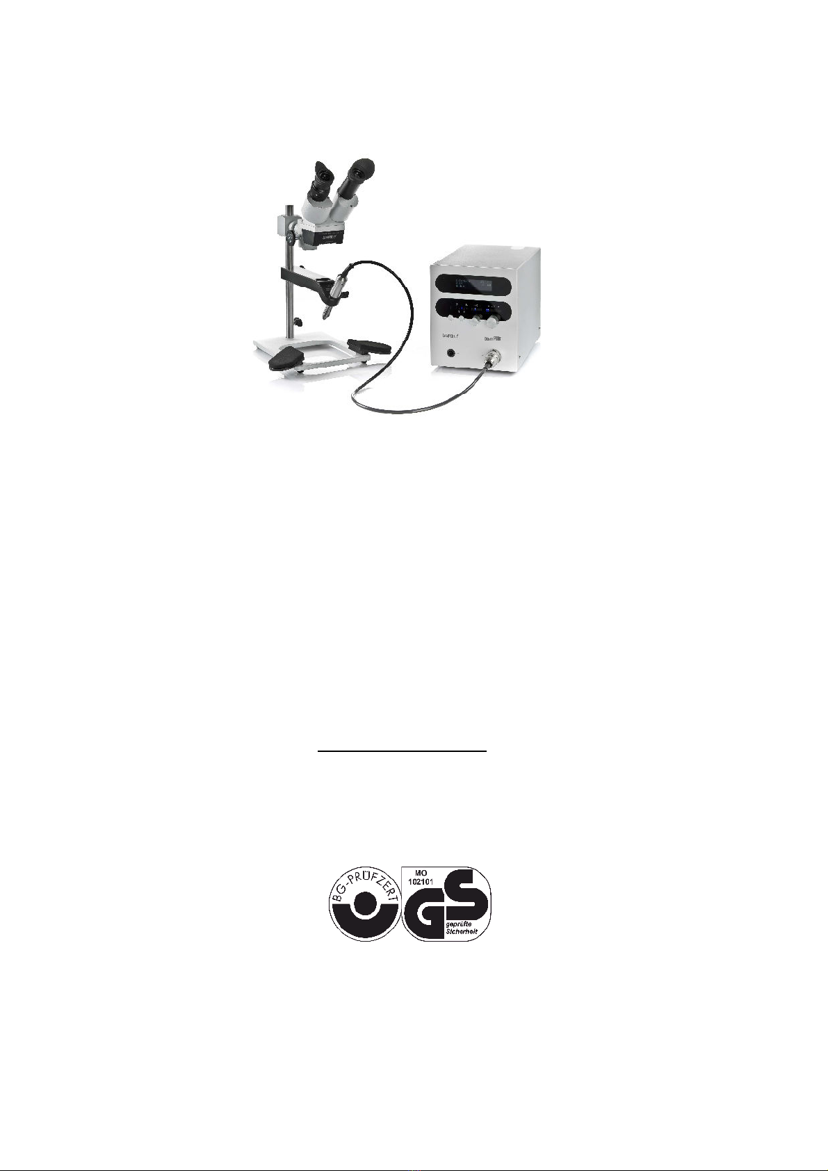
In its standard serialised form, the DENTA PUK must be run on a mains voltage of
230V~.
The wiring of the mains power supply plug is as follows: yellow-green lead = equipment
grounding conductor (PE). The other two leads L1 and N, are connected to the Phase
und Neutral terminals of the plug.
Since the launch of the Euro Norm IEC 38 (valid from May 1987), the mains voltage is
defined Europe-wide as 230V.
The welding device is set ex works, to run on 230V!
This means that the equipment can, because of the tolerance range of +/-15%, also be
run on a mains power of 220V~. Machines that have been “factory set” to run on a
voltage other than 230V are specially labelled with an appropriate sticker.
THE DEVICE MAY ONLY BE OPENED BY AUTHORIZED PERSONNEL!
IF THE DEVICE HAS BEEN MADE FOR A VOLTAGE OTHER THAN THE STANDARD
VOLTAGE OF 230V~, THEN THE TECHNICAL DATA INDICATED ON THE
IDENTIFICATION PLATE IS APPLICABLE! MAINS PLUGS MUST CORRESPOND
WITH THE MAINS VOLTAGE AND THE CURRENT CONSUMPTION OF
THE WELDING DEVICE. (See the technical data!)
ALWAYS USE FUSE THAT IS APROPRIATE AND SUITABLE FOR THE MACHINES
CURRENT CONSUMPTION.
USE ONLY THE POWER CORDS PROVIDED!

5
3-2 PERSONAL SAFETY AND POTENTIAL RISKS
When welding it is preferable to wear protective gloves on both hands, as it cannot be
completely ruled out that sparks and splashes occur during welding. The protective
gloves may not contain high proportions of quickly melting synthetic fibres. Protective
gloves also guard against UV-rays which are harmful during prolonged periods of
intensive welding.
Wear appropriate clothing with no synthetics.
The work piece and electrode tip can become extremely hot during welding, bringing a
possible risk of burns.
The point of the electrode, when clamped into the hand piece, signifies a risk of injury.
(Wounds caused by piercing or scratching of the hand, face, eyes, etc….).
Do not look into the arc without adequate eye protection. Only use a welders’
protective glare shield that contains a protective glass which conforms to
regulations (protection class 11, minimum).
The electric arc radiates rays of heat and light that can cause the user to be burned or
dazzled. In Addition to this, the arc also gives off UV-radiation. If the eyes are not
adequately protected, these invisible ultraviolet rays can cause a very painful
conjunctivitis, the effects of which are only noticeable several hours after exposure.
Those lingering or working in close proximity to the electric arc, must be made aware of
the risks, and supplied with the appropriate protective equipment. Wherever necessary, a
protective screen should be erected.
When welding, especially in confined spaces, always make sure that there is enough
fresh air, as smoke and harmful gases are produced.
Because of the danger of explosions, no welding may be carried out on any containers
that have previously held gasses, fuels, petroleum, mineral oils or similar; even if these
have been standing empty for a prolonged period.
Specific regulations apply in high fire-risk and explosion-risk rooms or areas.
DANGER FROM SHIELDING-GAS CYLINDERS
When handling gas cylinders, always abide by the appropriate safety regulations.
In particular, gas bottles are to be safeguarded and secured so that they can neither
topple over nor fall off anything. In addition they are to be protected against thermal
shock so that they cannot heat up to above 50°C or are subjected to severe frost. A
prolonged contact to the suns rays is also to be avoided.
4 INSTALLATION
4-1 SET-UP GUIDELINES
The device is to be placed so that cooling air can freely circulate and reach all surfaces
of the machine.
The device must not be covered!
Always place the machine on a hard, insulating and non-combustible base material.
No metal dust, that may occur or accumulate (e.g. during abrasion work), may be
allowed to enter the machine.

6
4-2 CONTROLS, FUNCTIONS AND FEATURES - FRONT
(Fig. 1)
1 2 3 4
6 5
(1)
BUTTON-PROGRAM MEMORY
(2)
BUTTON-SWITCHING MODES
(3)
ROTARY KNOB-IMPULSE LENGTH / WELDING TIME
(4)
ROTARY KNOB-WELDING POWER
(5)
SOCKET FOR THE HANDPIECE (-pole )
(6)
SOCKET ( + pole)
For connecting accessories designed to complete the electrical circuit (i.e. crocodile clip,
or other connecting cables)
LCD-DISPLAY
(7)
(8)
(9)
(10)
(7) Power in percent (%)
(8) Impulse length (welding time) in Milliseconds (ms)
(9) Current mode setting: Standard mode / Pulse welding mode / Soft welding mode / Pin
welding mode / Micro mode
(10)
Program indicator P1-P10 (P1-P5 are pre-programmed at the factory)
The foot switch function can be recognised by this symbol ↓. The foot switch itself is an
optional accessory.
Please note: In the following cases the machine will switch automatically to its standby
setting after 2 minutes:
- If no weld has taken place during this time.
- If the machine has not been otherwise operated or the parameters changed during
this time.
Whilst on standby, only 1 of the blue “Power” LEDs will light.
To switch the machine again to its operational mode, activate any one of the controls, or
complete the electrical circuit (contact the electrode with a work piece that is connected
via the crocodile clip). Once done, the machine is then instantly usable again and is
ready to work.

7
4-3 CONTROLS, FUNCTIONS AND FEATURES - BACK
(Fig. 2)
11 12
15
19 14
18
13 17
16
(11)
MAINS POWER SWITCH
(12)
I.E.C. POWER CONNECTOR
For connecting the mains power cable
(13)
CONNECTION SOCKET FOR GLARE PROTECTION SYSTEM (“Shutter / Welding
Shield”)
(14)
CONNECTION SOCKET FOR FOOT SWITCH (“Foot Switch”)
(15)
CONNECTION SOCKET FOR LED MICROSCOPE LIGHTING (“LED-Lamp 800 mA”)
Please note: The connection sockets for the foot switch, the glare protection
system and the LED microscope lighting are identical!
(16)
CONNECTOR FOR INERT GAS HOOKUP (“ARGON GAS”)
For pressure hose Ø 6 mm
(17)
IDENTIFICATION PLATE
(18)
FUSE TRAY (“Fuse”)
(19)
SERIAL NUMBER
4-4 SETUP INSTRUCTIONS AND COMMENCING WORK
Setup:
The machine is always to be placed on a hard, insulating and non-combustible base
material, ideally on a work bench.
Push the connector plug of the hand-piece as straight as possible into the socket (5) and
by turning it to the right, carefully tighten the plug. (Hand tight only).
Insert the connector of the terminal clamp being used (i.e. crocodile clip) into its socket (6).

8
Inserting the electrode:
Before changing the electrode, please check and make sure that the machine is switched
off. The uncontrolled triggering of a welding impulse can hereby be avoided.
(Fig. 3) (Fig. 4)
Remove the argon nozzle (22) from the hand-piece (25) by twisting it in opposite
(alternate) directions, and gently pulling.
Unscrew the clamping nut (24), and insert a freshly sharpened tungsten electrode (23),
then tighten the clamping nut. (Hand tight only).
UNDER NO CIRCUMSTANCES IS A SPANNER TO BE USED TO TIGHTEN THE
CLAMPING NUT.
Ideally, the electrode should protrude 4 - 6mm out of the nozzle (when replaced). (Fig. 4)
(Only use original, Thorium oxide free, electrodes).
Now replace the argon nozzle again.
Please note!
Argon nozzle (22), clamping nut (24), collet and electrodes (23) are all wear parts
(spare parts), and are therefore not covered by our warranty.
Connecting the glare protection system:
The round plug for the shutter (glare protection system “welding microscope SMD”) is
inserted into the socket marked “Shutter / Welding Shield” (13) on the back of the machine,
and with aid of the nut, tightened. (Hand tight only).
Caution!
Only the Lampert-glare protection system “welding microscope SMD” may be
connected to the DENTA PUK.
Other glare protection systems are not permitted and can result in permanent health
damage or lead to the damaging of the machine.
Please note!
Before starting to weld, always check to make sure that the eye-protecting filter
(Shutter) is functioning correctly.
By pressing in the rotary knob power (4), the eye protecting filter will change from
its clear setting (Luminescence DIN3) to its dark setting (Obscurity DIN11) and back
again when released.
Should the eye protecting filter (shutter) not change from its light to dark setting,
then it must be immediately replaced before any further work is carried out.
Connecting the gas supply:
Mount the flowmeter regulator to the bottle of inert gas, observing hereby the enclosed
instruction manual. (Wherever possible, use Argon with a purity of 99,99% i.e. “Argon 4,6“.
Mount the pressure hose to the quick coupling pieces on the flowmeter regulator, and the
connector for inert gas on the back of the machine (16); fasten these (Hand tight only).
Only use original pressure hose – supplied.
Check all the pressure hose connections to ensure that they are all secure and there
are no gas leaks.
When all is correctly connected, open the valve on the gas bottle, and set the pressure on
the flowmeter regulator to ca. 2litres per minute.
To fine tune the flow rate to the correct amount 2litres per minute, please see part 5 of
these instructions below.

9
The maximum operating pressure is 4 bar!
Please note!
The DENTA PUK will only work when hooked up to a supply
of inert gas and only when the machine is receiving enough
pressure (ca. 2 litres/min).
If inert gas is not hooked up, not flowing or if the pressure is
too low, the display will show the following reading: “Gas
error!! Please check the gas pressure”.
Connecting the power supply:
Insert the mains power cable into I.E.C power connector (12), and
insert the plug into the mains power socket.
Switch the mains power switch (11) to “ON”. The display will show
the following important safety warning “Warning! Protect your
eyes! Read the manual! Follow the advice!”
Confirm the compliance with these safety instructions, by pressing
any button. Following this, the machine will run a self-test.
Please note!
Please also follow the guidelines given in the operating
instructions of the attached welding microscope “SMD”!
Caution!
As soon as the mains power switch is switched to “ON”, the
terminal clamp (i.e. crocodile clip) and cables receive
electrical current. Please see to it that these items cannot
come into contact with any electrically conducting or earthed
materials. For the user / operator there is no danger, but
unwanted operating errors can occur.
4-5 CHANGING LANGUAGE DISPLAYED:
Languages available: ENGLISH – ITALIAN – SPANISH – FRENCH – GERMAN
The machine can be changed from English to run in any of the 4 other languages
mentioned above.
Switch the machine on and confirm the safety notice displayed, so that the device starts
and is ready for work.
Now press both the “Mode“ button (2) and the rotary-knob “Power“ (4), holding
them pressed for 2 seconds.
The language setting has now been changed to the next language in sequence.
By repeating this process, the various languages available can be selected one after the
other.
5 OPERATING PRINCIPLES AND SETTING THE PARAMETERS
After being switched on and running the self-test, the machine will start from its initial
settings:
Standard mode, 7 ms impulse length/welding time, and a low power setting.
The initial settings for mode, welding time and power, correspond to the blue LEDs in the
display. The display also has blue LEDs to mark the entire parameter range.

10
Important !
At the outset, until a basic proficiency is reached, we recommend to only change the
parameter welding power, leaving the welding time constant. After a short time, when
you have become more confident with the technique and have gained more experience,
then you can naturally also change the welding time to suit your needs.
The machine automatically saves the last three sets of welding parameters that
have been used.
By pressing in the rotary knob “Impulse length / welding time” (3), these previous settings
can be recalled one after another.
Even when the machine is switched on, or after accidentally changing the parameters,
the settings that were last used are there to be recalled again.
Please note !
Please remember that only when the gas flow rate has been correctly set up and
adjusted, can good welding results be achieved.
To adjust the gas flow to the correct amount, press in and hold the rotary knob – welding
power (4). (The gas valve in the machine will now be open and the gas flowing freely).
Without letting go of the rotary knob welding power (4), adjust the flowmeter regulator to
the correct flow rate ca. 2litres per minute.
5-1 SETTING THE WELDING PARAMETERS
Power:
The welding power (potency of the welding energy), can be set by adjusting
the rotary knob – welding power (4)
The size and intensity of the welding spot can thus be governed.
Welding time:
Using the rotary knob – Impulse length / welding time (3), the user can
regulate for how many milliseconds the welding energy impacts upon the work
piece.
Depending on the angle at which the electrode is held in relation to the work
piece, the penetration depth and direction of flow (of molten metals), can be
influenced.
The penetration depth is at its greatest when the electrode is held vertically to
the work piece.
A description of the welding modes:
Standard mode
Welding time 4-30ms, Power 20-100%
Our all-round program for many different applications.
Pulse welding mode
Welding time 4-30ms, Power 20-100%
Possible uses: grooves or joints, the inner surface of crowns, joints in tight
angles on model cast dilatations, small cavities.

11
Soft mode
Welding time 4-30ms, Power 20-100%
Especially well adapted to adding metal with welding wires, (the impulse form
is, in this case, even “softer on the electrode” than the standard impulse).
Pin welding mode
Welding on retentions on resin saddles, or pins.
Micro mode
Welding time 4-12ms, Power 5-32%
This modes parameters have lower output levels that can be set in finer
increments, making it ideal for very small cross-sections of material, for wires
or orthodontics.
Especially important to note: always use a sharp electrode!
5-2
USING THE PROGRAMMABLE MEMORY
RECALLING STORED SETTINGS (Program slot 1 – 10)
Apart from the 5 pre-programmed memory slots, this feature brings the
possibility to personalise and store the users own welding parameter settings,
into 5 additionally available memory slots. These settings can then be recalled
at a moments notice.
Please note!
The parameter settings of the pre-programmed memory slots, represent
recommended guideline values for “normal” material thicknesses.
Especially when working with thin or delicate constructions, it is
advisable to start with lower output levels, so that the work piece
doesn’t become damaged; if necessary, the settings can be re-adjusted
at any time.
By pressing (short) the button – program memory (1) and then releasing it, the
individual memory slots can be accessed.
STORING SETTINGS INTO THE MEMORY (Program slot 6 – 10).
Press the button – program memory (1) (long – ca. 1 sec.) and then releasing
it, the process for storing the current user settings is initiated.
Press the button – program memory (1) (short)and then releasing it, the
memory slot can be selected in which the settings are to be saved. (Program
slot 6 – 10)
Press the button – program memory (1) (long – ca. 3 sec.) and then releasing
it, the settings are saved into the selected slot. The display will show the
notice “Settings stored. Please enter the name of the program”.
Now the memory slot can be given a name (up to 10 characters).
By turning the rotary knob – welding power (4), the icon (number, letter), in
the selected character, can be changed.
To select the next character in the row, press and release the rotary knob –
welding power (4)

12
Finally, to store the settings and name into the selected memory slot, press
and release the rotary knob – Impulse length / welding time (3). The display
will show the notice “Your text was stored” the programming process is now
completed.
Please note!
If the user tries to save a set of parameters that is identical to one that is
already stored (or identical to one of the pre-programmed settings), the
display will show the following error notice. “Settings identical to program –
X Settings not stored!”. This is to avoid the “blocking” of a memory slot with
a duplication of already stored information.
In this case the memory slot, where the original setting is stored, will blink.
The process can then be cancelled by pressing the rotary knob – welding
power (4).
6 INSTRUCTIONS FOR USE
6-1 WELDING INSTRUCTIONS (Standard- / Pulse- / Soft- / Micro-mode)
(For instructions regarding the foot switch, please refer to chapter 6-2 where this subject
is handled separately).
Attach one of the terminal clamps (i.e. crocodile clip) to a part of the work piece where
the bare metal is exposed.
Gently touch the area (or item) to be welded with the tip of the electrode.
Maintain the contact until the weld has been produced.
Please note !
Do not apply force when the electrode tip touches the work piece; work using no
pressure, or only the slightest of pressure !
The welding process runs automatically:
o Inert gas circulates around and encases the welding area.
o A signal tone indicates that the arc is about to be fired.
o The arc is released.
o The flow of inert gas stops.
By withdrawing the work piece from the electrode, the welding process can be
interrupted.
WELDING INSTRUCTIONS (Pin welding mode)
(For instructions regarding the foot switch, please refer to chapter 6-2 where this subject
is handled separately).
Please note !
The pin welding mode is designed solely for the purpose
of welding on pins (Ø 1,3 mm) using the provided pin welding adapter.
Please switch the machine off before changing the electrode or changing to or from the
pin welding adapter. This is a safety precaution which will safeguard against the
uncontrolled triggering of a weld.
When changing to the pin welding mode, remove the electrode, clamping nut and collet,
and replace this with the pin welding adapter.
In the pin welding mode, always work without clamping nut and argon nozzle.
Attach one of the terminal clamps (i.e. crocodile clip) to a part of the work piece where
the bare metal is exposed.

13
Insert a pin (Ø 1,3 mm) into the pin welding adapter.
The welding process runs automatically:
1. When the pin is gently connected with the work piece, the pin welding adapter will
retract, and a signal tone will sound for 3 seconds.
2. By gently contacting the work piece a second time with the adapter, the welding
process is triggered. (This second contacting, must occur during the 3 seconds of the
signal tone, otherwise the welding process is automatically stopped).
We recommend using the pre-programmed memory slot no. 5 as the standard
setting for this mode.
Please note!
No gas is released during the entire pin welding process.
6-2 WELDING WITH THE FOOT SWITCH (optional accessory)
Make sure that the DENTA PUK is switched off. Attach the foot switch cable to the
socket “Foot Switch” on the back of the machine.
Next switch the machine back on,
The display will show the following important safety warning: “Warning! Protect your
eyes! Read the manual! Follow the advice!”
Confirm the compliance with these safety instructions, by pressing any button. Following
this, the machine will run a self-test.
The machine is now ready for use.
The foot switch can be activated, by pressing and holding it for ca. 1 second. The display
will show the symbol ↓.
In Standard-/ Pulse-/ Soft-/ Micro-mode:
Attach one of the terminal clamps (i.e. crocodile clip) to a part of the work piece where
the bare metal is exposed.
If the work piece is brought into contact with the electrode, the glare protection system
(shutter) inside the microscope SMD will flicker in a clearly visible manner.
Whilst in this operating status, if the foot switch is pressed, the welding process will run
automatically, just as described in chapter 6-1.
In Pin welding mode:
Please note!
The pin welding mode is designed solely for the purpose of welding on pins (Ø
1,3mm) using the provided pin welding adapter.
Please switch the machine off before changing the electrode or changing to or from the
pin welding adapter. This is a safety precaution which will safeguard against the
uncontrolled triggering of a weld.
When changing to the pin welding mode, remove the electrode, clamping nut and collet,
and replace this with the pin welding adapter.
In the pin welding mode, always work without clamping nut and argon nozzle.
Attach one of the terminal clamps (i.e. crocodile clip) to a part of the work piece where
the bare metal is exposed.
Insert a pin (Ø 1,3 mm) into the pin welding adapter.
1. When the pin is gently connected with the work piece, the pin welding adapter will
retract.
2. By gently contacting the work piece a second time with the adapter, the glare
protection system (shutter) inside the microscope SMD will visibly flicker.

14
If then the foot switch is pressed, the welding process will be triggered.
Please note! No gas is released during the entire pin welding process.
Please note!
During step “2.” Above (whilst the shutter is flickering), if the foot switch is not pressed
within 5 seconds, a constant signal tone will commence. This is a warning, and is
designed to protect the hand-piece solenoid from overloading in the case of unintentional
contact.
By again holding the footswitch pressed for ca. 1 second, (without contacting the work
piece) the footswitch function can be deactivated. The symbol ↓will disappear from the
display.
6-3 WORKING WITH THE ADAPTER CABLE FOR WELDING PINS (Ø1,3mm)
The pin welding mode gives the user the possibility weld on pins (Ø 1,3 mm). Here the
provided adapter cable is utilised, to enable a better contact to the work piece.
After the pin is welded on to the work piece, the cable can simply be slotted on to the pin,
thus providing the optimum contact with the DENTA PUK, so that further welding work
can be carried out. (This is especially advantageous for all work where contacting the
work piece with the other provided tools (i.e. crocodile clip), proves difficult.
The pin is only a “temporary aid” that must not withstand high levels of
mechanical stress. As it will be removed again after the welding work is
completed, it is important to remember to use a low power setting when welding it
on. This will ensure that the pin can be easily removed and polished afterwards.
This can be a very useful method, i.e. when wanting to carry out a weld on a model cast
denture that is already mounted to a model.
It is best to choose a place on the work piece that is sufficient in size and is not prone
warping or distortion; also important, is that the chosen spot for the pin is easy to finish
and polish afterwards.
After the work is finished, the pin can be easily removed again, and the welding area
cleaned with the rest of the work piece after all welding is completed.
6-4 TIPS AND GENERAL POINTERS
Important !
Always work with a well sharpened electrode !
This is the only way to achieve optimum results.
Always make sure that the work piece has a good contact to the
connecting terminal (i.e. crocodile clip).
In case of problems that arise as a result of poor electrical contact,
attach the connecting terminal to a part of the work piece where the
bare metal is exposed.
Never weld “freehand“, meaning: always lay both hands on the
hand-rests; this will aid in steadying the hands. If the hands shake,
the parameters of the device can be falsified and the welding result
affected.
Do not apply force when the electrode tip touches the work piece;
work using no pressure, or only the slightest of pressure !
Weld using only a low gas pressure !
In most cases about 2 l/min is enough.

15
TIPS
Take the time to get to know the machine its modes and operating techniques.
Try out the various output levels that the machine has to offer.
Bear in mind that every material reacts differently when welded, according to its heat-
conductivity.
When choosing the output levels of parameters, make allowances for the thickness of the
material which is to be welded and adjust settings accordingly.
Work with as much precision as possible: contact the electrode tip as precisely as you
can to the area where the weld is needed.
With experience you will observe that, the angle at which the electrode contacts the work
piece, has an impact on the “direction of flow” of the welding spot.
The deepest penetration into the material is achieved when the electrode is held at a 90°
angle to the work piece.
When working on “deep laying” or recessed welds, the electrode can be allowed to
protrude slightly further out of the nozzle. In this case, the gas-flow rate should be slightly
increased.
If holes or pores are to be closed, or existing joints and parts strengthened, extra material
will be needed. Here, it can be helpful use an appropriate welding wire.
6-5 SHARPENING THE ELECTRODES
Please switch the machine off before changing the electrode; this is a safety precaution
which will safeguard against the uncontrolled triggering of a weld.
The electrode should be sharpened using a diamond grinding wheel, preferably one that
has a fine or middle grain.
The grinding angle should be 15°, (see the diag ram above).
6-6 CARE AND MAINTENANCE
Under normal working conditions, the DENTA PUK needs only a minimum of
maintenance and care. However, it is necessary to observe a few vital points, to ensure
that the device remains operable, and gives lasting service in the years to come.
Regularly check all cables and plugs to make sure that they are not damaged.
Check the moving parts of the hand-piece to ensure ease of mobility.
Whenever necessary, clean the thread under the clamping nut of the hand-piece (see
Fig. 3 no. 24 on page 8), to ensure that the electrode has a perfect contact with the hand-
piece.
to Warning !
IF FUSES NEED TO BE EXCHANGED; THESE ARE ONLY TO BE REPLACED WITH
FUSES OF THE SAME SPECIFICATION. USING FUSES OF A HIGHER VALUE WILL
INVALIDATE ANY WARRNTY CLAIMS !
The DENTA PUK may only be opened by an electrician, electrical technician or
other qualified personnel who are familiarised with these products.

16
7 TECHNICAL DATA
7-1 TECHNICAL DATA
■
Device suitable solely for indoor-welding in dry surroundings!
■
Humidity
Max. 80 % up to 31°C,
Max. 50 % 31°C-40°C
■
Elevation Not over 2000m NN
■
Mains voltage ~230 V / 50-60 Hz +/-
15%
■
Fuse T 3,15 A
■
Power input 400 VA
■
Closed-circuit voltage 20 – 43 V
■
Open-circuit voltage 43 V
■
Duty cycle X 80%
■
Max. charging time 0,8 s
■
Inert gas min. ARGON 99,8%
■
Maximum Gas pressure 4 bar
■
Protection category I
■
Insulation class B
■
Degree of protection IP 21S
■
Weight “DENTA PUK” 8,8 kg
7-2
Identification plate
Explanation of picture symbols
Amperage
Voltage
Degree of
protection
Hertz
Alternating
current (AC)
Tungsten-inert-
gas welding
Direct current
1 ~ 50-60Hz
Power plug
single phase /
Alternating
current / 50-
60Hz
Read the
manual
Rated no-load
voltage
Rated supply
voltage
Protective
earth
Conventional
load voltage
Rated welding
current
Single phase
transformer
Rated max.
supply current
Max. effective
supply current
Duty cycle

17
8TROUBLE SHOOTING
FAULT CAUSE SOLUTION
1
No power
Mains power switch is switched on,
but the display does not light up.
The power supply (feeder) to the
machine is interrupted or
machine’s internal fuse defective
Check the mains power cable and
mains voltage or replace fuse with
a suitable fuse of the same type
and value.
2
No welding current
Mains power switch is switched on,
but the machine does not weld.
The power supply (feeder), from
the machine to the hand-piece is
interrupted.
Check the connections (connector
and socket).
Mains power switch is switched on,
but the machine does not weld.
Bad, or no connection to
protective ground
Create a connection between the
machine and the work piece.
Attach one of the terminal clamps
(i.e. crocodile clip) securely to a
part of the work piece.
3
No welding current
Mains power switch is switched on Problem caused by fault current
(abnormal current in an electric
circuit due to a fault, usually a
short circuit or abnormally low
impedance path).
Switch the machine off and then
on again via the mains power
switch.
If the problem persists, the
machine will need servicing,
please contact your dealer.
4
Circuit breaker is triggered, or
mains fuse blows
The mains fusing is too weak or
the wrong circuit breaker is being
used.
Correctly fuse the mains power
supply.
Mains fuse blows as soon as the
machine is switched on.
The machine will need servicing,
please contact your dealer.
5
Bad welding result / bad welding
characteristics
The wrong inert gas is being
used.
Use Argon inert gas.
Wherever possible, use Argon
with a purity of 99,996% i.e.
“Argon 4,6”.
6
Oxidation and the forming of
soot
The gas pressure is set too high. Reduce the flow rate-ca. 2 L/min.
is sufficient.
7
Welding spots are heavily
oxidised.
The wrong inert gas is being
used.
Use Argon inert gas.
Wherever possible, use “Argon
4,6”.
8
Tungsten inclusions in the work-
piece
The electrode is being pressed
too hard onto the work piece.
Work using no pressure, or only
the slightest of pressure; do not
apply force!
9
Tungsten electrode “sticks“ to
the work piece when welding
The electrode is being pressed
too hard onto the work piece.
Work using no pressure, or only
the slightest of pressure; do not
apply force!
10
Tip of tungsten electrode melts
off as soon as welding starts.
The angle, at which the electrode
is sharpened, is too acute.
Recommended grinding angle is
ca. 15°.
11
Discharge of static electricity
across the surface of the
machine.
Due to special local conditions
Use a special antistatic mat for
the working area.
12
Glare protection system (Shutter)
in not working
The plug of the glare protection
system is not correctly connected.
Insert the plug of the glare
protection system into the socket
marked “Shutter/Welding Shield
”
(Fig 2 no.13 page 7).

18
13
The machine welds immediately
after the electrode contacts the
work piece (no delay for gas to
flow, prior to the welding
process)
Technical malfunction
Immediately take machine out of
operation. It must be shut down
and removed from the power
supply; it must also be secured
against accidental re-operation or
activation.
The machine will need servicing,
please contact your dealer.
Warning !
The DENTA PUK may only be opened by an electrician, electrical technician or
other qualified personnel who are familiarised with these products!
Text and images correspond to, and represent the current technological state at the time of
publication and are subject to change without notice.
Our products are manufactured to exacting standards. Produced with care, they undergo
meticulous testing processes to ensure high quality and length of product life.
Nevertheless should the welding device malfunction, you are assured of our support and a
competent service.
Should reconditioning, maintenance or repairs be necessary at any time, this may be carried out
solely by Lampert Company, its staff or from Lampert authorised service points. Please always
have the Serial number of the machine ready when responding to, or making any enquiries.
Service address and contact details
:
LWT-Service Centre
Ettlebener Strasse 27b
D-97440 Werneck
9 SPARE PARTS LIST
■Hand-piece:
25 Hand-piece complete DP100 100
22 Argon nozzle DP100 150 K
26 Collet DP100 151
24 Clamping nut DP100 152
■Electrodes:
Electrodes (Thorium oxide free), 10 pcs. in display box, including
1 diamond grinding wheel
DP100 401
■Diamond grinding wheel:
Diamond grinding wheel DP100 701
■Gas hose:
3m gas hose 6x4mm (max. 10bar) DP100 153

19
10 DISPOSAL INFORMATION:
Devices that are no longer in use (waste), can be made unserviceable by removing the
mains power cable.
For EU countries only:
As specified in European directive 2002/96/ EG on waste electrical and electronic
equipment, used electrical appliances must be collected and stored separately and
introduced into an environmentally compatible disposal system.
11 EG-CONFORMITY DECLARATION
The Manufacturer,
Lampert Werktechnik GmbH
Ettlebener Str. 27, D-97440 Werneck
Declares herewith that the following product:
Precision welding device
“DENTA PUK”
Complies with the provisions of the below mentioned directive, including any
amendments hereof, that were valid at the time of declaration.
Relevant EC guidelines:
According to low voltage guidelines 2006/95/EG
According to EMV (electro-magnetic compatibility) guidelines 2004/108/EG
The following harmonised standards were used:
EN 60974-6
EN ISO 12100-1
EN ISO 12100-2
Person duly authorised to carry out technical documentation: N. Hammer
Werneck, 30.10.2009
Lampert Werktechnik GmbH
Andrea Bauer-Lampert (Managing Director)
Table of contents
Other Lampert Welding System manuals

Lampert
Lampert PUK 3 professional plus User manual

Lampert
Lampert PUK04 User manual

Lampert
Lampert PUK D2 User manual

Lampert
Lampert PUK S450 User manual

Lampert
Lampert PUK 111 User manual

Lampert
Lampert PUK U5 User manual

Lampert
Lampert PUK 2 User manual

Lampert
Lampert PUK U3 User manual

Lampert
Lampert PUK5.1 User manual

Lampert
Lampert M280 User manual
Popular Welding System manuals by other brands

Hwayuan Electric
Hwayuan Electric ZX7-200 instruction manual

Chicago Electric
Chicago Electric 62719 Owner's manual & safety instructions

Saf-Fro
Saf-Fro DIGISTEEL 255C Operator's manual

Ferm
Ferm CONCEPT 1500 user manual

Chicago Electric
Chicago Electric MIG-100 91124 Assembly and operating instructions

Eastwood
Eastwood MP140i instructions