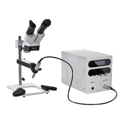
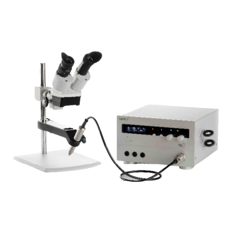
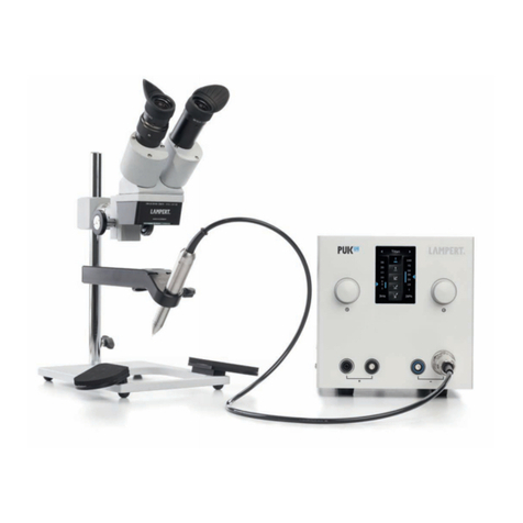
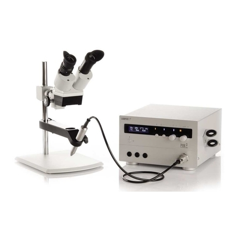
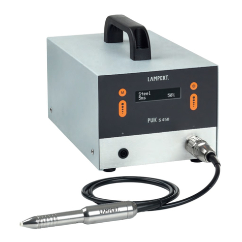
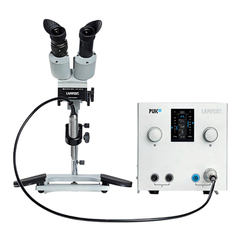
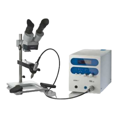
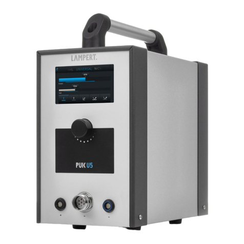
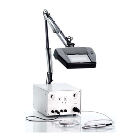
Lampert PUK 111 User manual

Operating Instructions
Precision Welding Device
PUK 111
and
PUK - Optic Device
Lampert Tools USA, Inc
115 V


1
PUK 111
Operating Instructions
115V
Dear Customer
This handbook is intended to help you with the
operation of your PUK 111. It is important to read
the instructions carefully and to follow the
directions closely in order to avoid disruptions
due to operating errors. By following instructions
properly, your equipment will always be ready for
use and serve you over a long lifespan.
Operation of the device should only be done
by trained professionals and be operated
according to the intended purpose of use.
The manufacturer is in no way liable for any
damage caused by improper use and
operation. Before use please be sure to read
the manual sections “General Safety
Requirements” and “Personal Protection”.
Please retain these instructions for reference.
Note on Symbol
The equipment manufactured by “Lampert
TOOLS GmbH“ fulfil the standard requirements
of CE certification and are manufactured
according to VDE guidelines.
The PUK is certified as “BG-
PRÜFZERT” by the Central
Professional Association and
carries the “GS Sign” (No. MO
022101)
Use original parts only for maintenance and
updating. Our customer service department with
expertly trained staff, suitable resources and
equipment would be pleased to help you further.
The device should only be opened or modified by
authorized customer service technicians,
otherwise all warrantees and liability claims will
be void.
LAMPERT TOOLS GmbH
August 2003

2
TABLE OF CONTENTS
SECTION 1 – GENERAL APPLICATION . . . . . . . . . . . . . . . . . . . . . . . . . . . . . . . . . . . . 3
SECTION 2 – INTRODUCTION . . . . . . . . . . . . . . . . . . . . . . . . . . . . . . . . . . . . . . . . . . . . 3
SECTION 3 – GENERAL SAFETY INSTRUCTIONS - READ BEFORE USING. . . . . . . 3
3-1. Safety Instructions . . . . . . . . . . . . . . . . . . . . . . . . . . . . . . . . . . . . . . . . . . . . 3
3-2. Personal Protection and Danger. . . . . . . . . . . . . . . . . . . . . . . . . . . . . . . . . . 4
SECTION 4 – SAFETY PRECAUTIONS - READ BEFORE USING . . . . . . . . . . . . . . . . 5
4-1. Arc Welding Hazards . . . . . . . . . . . . . . . . . . . . . . . . . . . . . . . . . . . . . . . . . . 5
4-2. Additional Symbols for Installation, Operation, and Maintenance . . . . . . . . . 7
4-3. Principal Safety Standards . . . . . . . . . . . . . . . . . . . . . . . . . . . . . . . . . . . . . . 8
4-4. EMF Information . . . . . . . . . . . . . . . . . . . . . . . . . . . . . . . . . . . . . . . . . . . . . . 8
SECTION 5 – INSTALLATION . . . . . . . . . . . . . . . . . . . . . . . . . . . . . . . . . . . . . . . . . . . . 9
5-1. Technical Data. . . . . . . . . . . . . . . . . . . . . . . . . . . . . . . . . . . . . . . . . . . . . . . . 9
5-2. Type Label Chart. . . . . . . . . . . . . . . . . . . . . . . . . . . . . . . . . . . . . . . . . . . . . . 9
5-3. Setting Up. . . . . . . . . . . . . . . . . . . . . . . . . . . . . . . . . . . . . . . . . . . . . . . . . . . 10
5-4. Description of Operating Components . . . . . . . . . . . . . . . . . . . . . . . . . . . . . 10
5-5. Starting the Welding Process . . . . . . . . . . . . . . . . . . . . . . . . . . . . . . . . . . . . 11
SECTION 6 – OPERATION . . . . . . . . . . . . . . . . . . . . . . . . . . . . . . . . . . . . . . . . . . . . . . . 12
6-1. Welding Guidelines . . . . . . . . . . . . . . . . . . . . . . . . . . . . . . . . . . . . . . . . . . . . 12
6-2. Basic Information and Tips . . . . . . . . . . . . . . . . . . . . . . . . . . . . . . . . . . . . . . 12
6-3. Grinding the Electrodes . . . . . . . . . . . . . . . . . . . . . . . . . . . . . . . . . . . . . . . . 13
SECTION 7 – MAINTENANCE AND TROUBLESHOOTING . . . . . . . . . . . . . . . . . . . . . 13
7-1. Routine Maintenance . . . . . . . . . . . . . . . . . . . . . . . . . . . . . . . . . . . . . . . . . . 13
7-2. Troubleshooting . . . . . . . . . . . . . . . . . . . . . . . . . . . . . . . . . . . . . . . . . . . . . . . 14
SECTION 8 – LIST OF SPARE PARTS. . . . . . . . . . . . . . . . . . . . . . . . . . . . . . . . . . . . . . 15
SECTION 9 – CONTACT. . . . . . . . . . . . . . . . . . . . . . . . . . . . . . . . . . . . . . . . . . . . . . . . . 16

3
SECTION 1 – GENERAL APPLICATION
•fixing or fastening work pieces prior to
soldering or other additional processing
•the placement of spot welding on precious
metal and precious metal alloys, on steel and
steel alloys as well as titanium and various
NE-metals such as
aluminium and brass
•not authorized for welding teeth fittings
(dental techniques)
•Operation in outdoor areas is prohibited. Use
in dry room areas only.
No liability of any kind will be assumed for the
durability of welding spots. We recommend
that you always check the spots and to solder
them in case of doubt.
SECTION 2 – INTRODUCTION
PUK111 provides a long-awaited missing link
between difficult joining techniques and laser
welding devices. With the help of an intelligent
combination of high performance electronics and
precision mechanics, we’ve been able to create a
unique spot welding device. It’s small size, low
weight and minimum energy use are important
factors leading to your advantage. Excellent
ignition and welding characteristics allow a broad
range of use. With our welding device, you’re
able to gain access to new dimensions of welding
techniques in the area of production and repair.
SECTION 3 – GENERAL SAFETY INSTRUCTIONS - READ BEFORE USING
3-1. SAFETY INSTRUCTIONS
•Opening the device is permitted only by
trained experts. Remove the plug before
opening the device and make sure that the
device is without electrical power. Discharge
all device components that may store
electricity.
•Please consult an expert should any
questions arise. Our customer service team
with expertly trained staff, necessary
resources and equipment would be pleased
to assist you further at any time.
•Always use original cables that are long
enough and make sure that the clamp
holding the work piece is fastened properly.
•Hazard conditions may be caused by
electricity as well as by welding current.
•It is illegal for non-professional electricians to
handle parts that are directly connected to
the mains power supply, except in cases of
pulling the mains plug and/or operating the
main power switch.
•The device must be disconnected from the
mains as soon as repair or service works is
needed. When leaving the place of work
even for a short time, make sure that the
electrical outlet is blocked clearly.
•Open circuit voltage is the highest and most
dangerous voltage for welding current. The
highest permitted open circuit voltages are
contained in your national and international
regulations according to the type of welding
current, type of electrical source and the high
or low hazard levels at the workplace.
•If you believe that operating the device is not
possible without creating hazardous
conditions, then shut off the device and
secure it against unauthorised use. It is clear
that a hazardous conditions are present
when:
othe device shows visible damage,or
oor when functional errors occur
oif it no longer functions properly.
•Please follow relevant safety measures when
handling gas bottles

4
PUK111 can be operated in series using a
mains voltage of 115V~
Yellow/green electric conductor = grounded
terminal (PE)
Other conductors L1 and N are connected to
phase and neutral of plug.
The welding device is set for 115 V ex works!
This means that it also may be operated using
115 volts due to its tolerance of +/- 15%. Devices
set to a different voltage than 115 V will be
marked with a special sticker.
If the PUK111 is switched for a voltage other
than 115V, it will have a sticker with the
corresponding voltage.
the device should only be opened by
authorized customer service, otherwise the
manufacturer`s warrantee is invalid.
if the device is setup for a special voltage,
technical data contained on the output sticker
are valid! Main plugs must correspond to the
supply voltage and the current consumption
of the welding device (see technical data)
The fuse protection must be set to the same
voltage as the current consumption of the
welding device.
Only use the Mains connection delivered with the
device.
3-2. PERSONAL PROTECTION AND DANGER
•Always wear insulated protective gloves
during the welding process to protect yourself
from electrical strokes (open circuit voltage)
from dangerous rays (heat and UV) and from
hot metal and slags.
•Wear strong and insulated footwear.
Footwear also must insulate under wet
conditions. Low shoes are not suitable, since
falling hot slags may cause burns.
•Wear suitable clothing - no synthetic fibers.
•Do not look into arc without protecting
your eyes. Use only a welders’ face
protection shield with protecting glass
that conforms to regulation (minimum
protection level 11).
The arc releases not only light and heat
causing blindness or burning but also emits
UV rays. If insufficient protection is used, the
UV beams can cause very painful
conjunctivital inflammation only noticeable
after several hours.
•Bystanders close to the arcs also should be
made aware of possible dangerous
conditions and should wear protective
equipment. If necessary protective walls
should be set up.
•If welding in small rooms, ensure that there is
sufficient ventilation since smoke and
dangerous gases can be generated.
It is prohibited by law to weld containers that
have been used for the storage of gas, fuel,
mineral oil etc., even if containers have been
standing empty for a long period of time.
Explosions may occur during the welding
process due to residue.
•Note any special regulations for rooms with
high fire or explosion hazards.

5
SECTION 4 – SAFETY PRECAUTIONS - READ BEFORE USING
4-1. Arc Welding Hazards
►The symbols shown below are used throughout this
manual to call attention to and identify possible
hazards. When you see the symbol, watch out, and
follow the related instructions to avoid the hazard.
The safety information given below is only a summary
of the more complete safety information found in the
Safety Standards listed in Section 1-4. Read and
follow all Safety Standards.
►Only qualified persons should install, operate,
maintain, and repair this unit.
►During operation, keep everybody, especially
children, away.
ELECTRIC SHOCK can kill.
Touching live electrical parts can
cause fatal shocks or severe burns.
The electrode and work circuit is
electrically live whenever the output is
on. The input power circuit and
machine internal circuits are also live
when power is on. In semiautomatic or automatic wire
welding, the wire, wire reel, drive roll housing, and all
metal parts touching the welding wire are electrically live.
Incorrectly installed or improperly grounded equipment is
a hazard.
_Do not touch live electrical parts.
_Wear dry, hole-free insulating gloves and body protection.
_Insulate yourself from work and ground using dry
insulating mats or covers big enough to prevent any
physical contact with the work or ground.
_Do not use AC output in damp areas, if movement is
confined, or if there is a danger of falling.
_Use AC output ONLY if required for the welding process.
_If AC output is required, use remote output control if
present on unit.
_Disconnect input power or stop engine before installing or
servicing this equipment. Lockout/tagout input power
according to OSHA 29 CFR 1910.147 (see Safety
Standards).
_Properly install and ground this equipment according to its
Owner’s Manual and national, state, and local codes.
_Always verify the supply ground – check and be sure that
input power cord ground wire is properly connected to
ground terminal in disconnect box or that cord plug is
connected to a properly grounded receptacle outlet.
_When making input connections, attach proper grounding
conduc-tor first – double-check connections.
_Frequently inspect input power cord for damage or bare
wiring –replace cord immediately if damaged – bare wiring
can kill.
_Turn off all equipment when not in use.
_Do not use worn, damaged, undersized, or poorly spliced
cables.
_Do not drape cables over your body.
_If earth grounding of the workpiece is required, ground it
directly with a separate cable.
_Do not touch electrode if you are in contact with the work,
ground, or another electrode from a different machine.
_Use only well-maintained equipment. Repair or replace
damaged parts at once. Maintain unit according to
manual.
_Wear a safety harness if working above floor level.
_Keep all panels and covers securely in place.
_Clamp work cable with good metal-to-metal contact to
workpiece or worktable as near the weld as practical.
_Insulate work clamp when not connected to workpiece to
prevent contact with any metal object.
_Do not connect more than one electrode or work cable to
any single weld output terminal.
SIGNIFICANT DC VOLTAGE exists after
removal of input power on inverters.
_Turn Off inverter, disconnect input power, and discharge
input capacitors according to instructions in Maintenance
Section before touching any parts.
FUMES AND GASES can be
hazardous.
Welding produces fumes and gases.
Breathing these fumes and gases can
be hazardous to your health.
_Keep your head out of the fumes.
Do not breathe the fumes.
_If inside, ventilate the area and/or use exhaust at the arc
to remove welding fumes and gases.
_If ventilation is poor, use an approved air-supplied
respirator.
_Read the Material Safety Data Sheets (MSDSs) and the
manufacturer’s instructions for metals, consumables,
coatings, cleaners, and degreasers.
_Work in a confined space only if it is well ventilated, or
while wearing an air-supplied respirator. Always have a
trained watch-person nearby. Welding fumes and gases
can displace air and lower the oxygen level causing injury
or death. Be sure the breath-ing air is safe.
_Do not weld in locations near degreasing, cleaning, or
spraying op-erations. The heat and rays of the arc can
react with vapors to form highly toxic and irritating gases.
_Do not weld on coated metals, such as galvanized, lead,
or cadmium plated steel, unless the coating is removed
from the weld area, the area is well ventilated, and if
necessary, while wearing an air-supplied respirator. The
coatings and any metals containing these elements can
give off toxic fumes if welded.
ARC RAYS can burn eyes and
skin.
Arc rays from the welding process
produce intense visible and invisible
(ultraviolet and infrared) rays that can
burn eyes and skin. Sparks fly off from
the weld.
_Wear a welding helmet fitted with a proper shade of filter
to protect your face and eyes when welding or watching
(see ANSI Z49.1 and Z87.1 listed in Safety Standards).
_Wear approved safety glasses with side shields under
your helmet.
_Use protective screens or barriers to protect others from
flash and glare; warn others not to watch the arc.
_Wear protective clothing made from durable, flame-
resistant material (leather and wool) and foot protection.

6
WELDING can cause fire or
explosion.
Welding on closed containers, such as
tanks, drums, or pipes, can cause them
to blow up. Sparks can fly off from the
welding arc. The flying sparks, hot
workpiece, and hot equipment can cause fires and burns.
Accidental contact of electrode to metal objects can cause
sparks, explosion, overheating, or fire. Check and be sure
the area is safe before doing any welding.
_Protect yourself and others from flying sparks and hot
metal.
_Do not weld where flying sparks can strike flammable
material.
_Remove all flammables within 35 ft (10.7 m) of the
welding arc. If this is not possible, tightly cover them with
approved covers.
_Be alert that welding sparks and hot materials from
welding can easily go through small cracks and openings
to adjacent areas.
_Watch for fire, and keep a fire extinguisher nearby.
_Be aware that welding on a ceiling, floor, bulkhead, or
partition can cause fire on the hidden side.
_Do not weld on closed containers such as tanks, drums,
or pipes, unless they are properly prepared according to
AWS F4.1 (see Safety Standards).
_Connect work cable to the work as close to the welding
area as practical to prevent welding current from traveling
long, possibly unknown paths and causing electric shock
and fire hazards.
_Do not use welder to thaw frozen pipes.
_Remove stick electrode from holder or cut off welding wire
at contact tip when not in use.
_Wear oil-free protective garments such as leather gloves,
heavy shirt, cuffless trousers, high shoes, and a cap.
_Remove any combustibles, such as a butane lighter or
matches, from your person before doing any welding.
FLYING METAL can injure
eyes.
_Welding, chipping, wire brushing,
and grinding cause sparks and flying
metal. As welds cool, they can throw
off slag.
_Wear approved safety glasses with side shields even
under your welding helmet.
BUILDUP OF GAS can injure
or kill.
_Shut off shielding gas supply when
not in use.
_Always ventilate confined spaces or
use approved air-supplied respirator.
HOT PARTS can cause
severe burns.
_Do not touch hot parts bare handed.
_Allow cooling period before working
on gun or torch.
MAGNETIC FIELDS can affect
pacemakers.
_Pacemaker
wearers keep away.
_Wearers should consult their doctor
before going near arc welding, gouging,
or spot welding operations.
NOISE can damage hearing.
Noise from some processes or
equipment can damage hearing.
_Wear approved ear protection if
noise level is high.
CYLINDERS can explode if
damaged.
Shielding gas cylinders contain gas
under high pressure. If damaged, a
cylinder can explode. Since gas
cylinders are normally part of the
welding process, be sure to treat them
carefully.
_Protect compressed gas cylinders from excessive heat,
mechani-cal shocks, slag, open flames, sparks, and arcs.
_Install cylinders in an upright position by securing to a
stationary support or cylinder rack to prevent falling or
tipping.
_Keep cylinders away from any welding or other electrical
circuits.
_Never drape a welding torch over a gas cylinder.
_Never allow a welding electrode to touch any cylinder.
_Never weld on a pressurized cylinder – explosion will
result.
_Use only correct shielding gas cylinders, regulators,
hoses, and fit-tings designed for the specific application;
maintain them and associated parts in good condition.
_Turn face away from valve outlet when opening cylinder
valve.
_Keep protective cap in place over valve except when
cylinder is in use or connected for use.
_Read and follow instructions on compressed gas
cylinders, associated equipment, and CGA publication P-1
listed in Safety Standards.

7
4-2. Additional Symbols For Installation, Operation, And Maintenance
FIRE OR EXPLOSION
hazard.
_Do not install or place unit on,
over, or near combustible surfaces.
_Do not install unit near flammables.
_Do not overload building wiring –
be sure power supply system is
properly sized, rated, and protected to handle this unit.
FALLING UNIT can cause
injury.
_Use lifting eye to lift unit only, NOT
running gear, gas cylinders, or any
other accessories.
_Use equipment of adequate
capacity to lift and support unit.
_If using lift forks to move unit, be
sure forks are long enough to extend beyond opposite
side of unit.
OVERUSE can cause OVER-
HEATING
_Allow cooling period; follow rated
duty cycle.
_Reduce current or reduce duty cycle
before starting to weld again.
_Do not block or filter airflow to unit.
STATIC (ESD) can damage
PC boards.
_Put on grounded wrist strap
BEFORE handling boards or parts.
_Use proper static-proof bags and
boxes to store, move, or ship PC
boards.
MOVING PARTS can cause
injury.
_Keep away from moving parts.
_Keep away from pinch points such
as drive rolls.
WELDING WIRE can cause
injury.
_Do not press gun trigger until
instructed to do so.
_Do not point gun toward any part of
the body, other people, or any metal
when threading welding wire.
MOVING PARTS can cause
injury.
_Keep away from moving parts such
as fans.
_Keep all doors, panels, covers, and
guards closed and securely in place.
H.F. RADIATION can cause
interference.
_High-frequency (H.F.) can interfere
with radio navigation, safety services,
computers, and communications
equipment.
_Have only qualified persons familiar
with electronic equipment perform this installation.
_The user is responsible for having a qualified electrician
prompt-ly correct any interference problem resulting from
the installation.
_If notified by the FCC about interference, stop using the
equipment at once.
_Have the installation regularly checked and maintained.
_Keep high-frequency source doors and panels tightly shut,
keep spark gaps at correct setting, and use grounding and
shielding to minimize the possibility of interference
.
ARC WELDING can cause
interference.
_Electromagnetic energy can interfere
with sensitive electronic equipment such
as computers and computer-driven
equipment such as robots.
_Be sure all equipment in the welding
area is electromagnetically compatible.
_To reduce possible interference, keep weld cables as
short as possible, close together, and down low, such as
on the floor.
_Locate welding operation 100 meters from any sensitive
elec-tronic equipment.
_Be sure this welding machine is installed and grounded
according to this manual.
_If interference still occurs, the user must take extra
measures such as moving the welding machine, using
shielded cables, using line filters, or shielding the work
area.

8
4-3. Principal Safety Standards
Safety in Welding, Cutting, and Allied Processes, ANSI
Standard Z49.1, from American Welding Society, 550
N.W. LeJeune Rd, Miami FL 33126 (phone: 305-443-
9353, website: www.aws.org).
Recommended Safe Practices for the Preparation for
Welding and Cut-ting of Containers and Piping, American
Welding Society Standard AWS F4.1, from American
Welding Society, 550 N.W. LeJeune Rd, Miami, FL 33126
(phone: 305-443-9353, website: www.aws.org).
National Electrical Code, NFPA Standard 70, from National
Fire Protec-tion Association, P.O. Box 9101, 1 Battery
March Park, Quincy, MA 02269–9101 (phone: 617–770–
3000, website: www.nfpa.org and www. sparky.org).
Safe Handling of Compressed Gases in Cylinders, CGA
Pamphlet P-1, from Compressed Gas Association, 1735
Jefferson Davis Highway, Suite 1004, Arlington, VA
22202–4102 (phone: 703–412–0900, web-site:
www.cganet.com).
Code for Safety in Welding and Cutting, CSA Standard
W117.2, from Canadian Standards Association,
Standards Sales, 178 Rexdale
Boulevard, Rexdale, Ontario, Canada M9W 1R3 (phone:
800–463–6727 or in Toronto 416–747–4044, website:
www.csa–in-ternational.org).
Practice For Occupational And Educational Eye And Face
Protection,
ANSI Standard Z87.1, from American National Standards
Institute, 11 West 42nd Street, New York, NY 10036–
8002 (phone: 212–642–4900, website: www.ansi.org).
Standard for Fire Prevention During Welding, Cutting, and
Other Hot Work, NFPA Standard 51B, from National Fire
Protection Association, P.O. Box 9101, 1 Battery March
Park, Quincy, MA 02269–9101 (phone: 617–770–3000,
website: www.nfpa.org and www. sparky.org).
OSHA, Occupational Safety and Health Standards for
General Indus-try, Title 29, Code of Federal Regulations
(CFR), Part 1910, Subpart Q, and Part 1926, Subpart J,
from U.S. Government Printing Office, Super-intendent of
Documents, P.O. Box 371954, Pittsburgh, PA 15250
(there are 10 Regional Offices––phone for Region 5,
Chicago, is 312–353–2220, website: www.osha.gov).
4-4. EMF Information
Considerations About Welding And The Effects Of Low
Frequency Electric And Magnetic Fields Welding current,
as it flows through welding cables, will cause electro-
magnetic fields. There has been and still is some concern
about such fields. However, after examining more than
500 studies spanning 17 years of research, a special blue
ribbon committee of the National Research Council
concluded that: “The body of evidence, in the committee’s
judgment, has not demonstrated that exposure to power-
frequency electric and magnetic fields is a human-health
hazard.” However, studies are still going forth and
evidence continues to be examined. Until the final
conclusions of the research are reached, you may wish to
minimize your exposure to electromagnetic fields when
welding or cutting.
To reduce magnetic fields in the workplace, use the following
procedures:
1. Keep cables close together by twisting or taping them.
2. Arrange cables to one side and away from the operator.
3. Do not coil or drape cables around your body.
4. Keep welding power source and cables as far away from
operator as practical.
5. Connect work clamp to workpiece as close to the weld as
possi-ble.
About Pacemakers:
Pacemaker wearers consult your doctor first. If cleared by
your doctor, then following the above procedures is
recommend.

9
SECTION 5 – INSTALLATION
5-1. TECHNICAL DATA:
o Device suitable for welding in dry rooms.
o Mains voltage ~ 115 V / 50-60 Hz +/- 15%
o Mains fuse T4,0 A
o Power input 500VA
o Operating voltage 20-38 V
o Open circuit voltage 38V
o Max. loading time 3 seconds
o Protective gas min. Argon 99.9 %
“Argon grade 5” (ARGON 4.6)
o max. gas pressure 10 bar
o Protection class I
o Insulation category B
o Protection type IP20
o Weight 5.25 kg
5-2. TYPE LABEL CHART
Description of symbols:
Amperes
Volts
Hertz
Alternating Current
Direct Current
1 ~ 50-60Hz
Line Connection
1 Phase / Alternating
Current / 50-60Hz
Rated No Load
Voltage (Average)
Primary Voltage
Conventional Load
Voltage
Rated Welding Current
Rated Maximum Supply
Current
Maximum Effective
Supply Current
Degree Of Protection
Protective Earth
(Ground)
Gas Tungsten Arc
Welding
One phase transformer
Note Manual
Duty Cycle

10
5-3. SETTING UP
•Place the device so that cool air can reach
the entire outside surface without difficulty
•Do not cover the device!
•Always place the device on a hard non-
combustible, insulated material base.
•Do not allow metal dust (e.g. during abrasion
work) to directly enter the device.
5-4.DESCRIPTION OF THE OPERATING COMPONENTS FRONT SIDE
(Figure 1)
ON RESET
WAIT READY
PUK 111
1
2
3
45
6
7
8
1
2
3
4
5
6
7
Main switch (1)
Reset button (2)
Charger signal (3) (red when charging)
Ready for use signal (4) (green when device
is ready for welding)
Sockets (5) for connection of contact
elements such as welding table, welding
clamp, holding pliers.
Output regulator (6) . Power regulated in 8
steps
Connecting socket for tool piece (7)
DESCRIPTION OF OPERATING COMPONENTS BACK SIDE
(Figure 2)
Connection of optical unit (8) for filter control
Connection for inert gas (9) for ∅6.0mm
pressure tube
Fuse box (10)
Plug (11) to connect to power supply

11
12 13 14 15
5-5. STARTING THE WELDING PROCESS:
The device must be set up on a flat and stable
surface, a work table is best suitable.
Attention: Do not plug the power plug into the
power outlet until you have completed
installation!
•Insert cable of tool right straight into socket
(7) turn tightly and carefully by hand to the
right to fasten
•Insert plug of welding table and/or clamp or
pliers into socket (5)
•Unscrew extruder die (12) from tool (15)
•Loosen electrode (14), insert newly grinded
wolfram electrode (13) and fasten it (do it
manually, do not use a tool) Let electrodes
extend past the extruder die by about 5 mm
(Fig. 3) (Only use original electrodes)
•Screw on extruder die (do it manually, not
with a tool)
•Plug the optic unit into the fastening block
located on the device, or alternatively fasten
it to the work table using the accompanying
table clamp
•Plug the round plug for the shutter into the
connection socket marked “Filter” located on
the back of the device and secure it with the
screw.
•To connect the microscope, plug in the round
plug and fasten it as like the optic unit above.
•Attach the pressure controller to the
protective gas container after carefully
reading the instructions (if possible, use
argon gas with a minimum of 99.8%, e.g.
“Argon grade 5” or “Argon 4.6”)
•Connect pressure tube, by using the quick
connectors, to the pressure controller and to
the gas connection (12) of housing backside
•Open gas bottle valve and set the gas flow to
between 3-5 liters (.014 cubic feet) per
minute - maximum operating pressure
should be 10 bar!
•Plug in main plug to grounded outlet 115V
(20amps)
•Set main switch (1) to ON – the device will
perform a self-test.
•The green control light (4) will indicate that
the device is in operational status.
•Use output regulator (6) to choose energy
needed.
•Start welding process.
•Use eye protection
.
Please read the instructions on the connected eye protection devices such as the optic unit or
microscope shutter!
ATTENTION!
When welding with PUK111, the welding base, the clamps and/or the pliers are live as soon as
the mains master switch is turned on. Make sure that these parts do not touch any electrically
conductive or earthed parts such as housing etc.

12
SECTION 6 – OPERATION
6-1. WELDING GUIDELINES
•Place the work piece on the welding table
•Make sure there is good contact between
work piece and table
•Use a clamp or pliers if the work piece only
has small contact with the table
•Use the electrode tip to touch the area you
want to weld until the welding is complete.
“without pressure or only with slight
pressure!”
•The welding process takes place
automatically:
oprotective gas floats around welding spot
oA short beep indicates the arc
othe arc sets off
oprotective gas supply stops
•The welding process can be interrupted at
any given time by lifting the electrode away
from the workpiece.
6-2. BASIC INFORMATION AND TIPS:
Important!
•Always work with a sharp edge
electrode to get optimal results.
•Always make sure that there is
enough contact between work piece
and welding table. In case of problems
use a clamp and/or pliers.
•Never weld “free hand”. That is,
always support both hands on the
base (work table). Trembling hands
will distort the parameter of the
device.
•Use only very light pressure on the
electrode tip.
•Weld only using low gas pressure! 3
to 4 litres (.014 cubic feet) per minute
is often enough.
Tips
•Take the time to familiarize yourself with
our device
•Test the various energy steps of the
device.
•Remember that materials may react
differently
•When choosing the energy step pay
attention to the thickness of the material.
•Touch the work piece exactly at the point
to welded.
•Once you are more familiar with the
device you will notice that angle you use
to touch the needle to the work piece will
influence the “flow direction” of the
welding spot. An angle of touch of 90°
will result in the deepest welding spot
possible.
•A saw or file with serrated edges is also
very suitable as additional welding
material
•Allow the needle to clamp in longer for
deep-lying welding spots.
•It may be helpful to punch out material by
chisel and weld them on.
•With a little experience you will be able to
use wire to close holes or to add support.
•If you problems igniting, it may be helpful
to lightly press the needle sideways.
Using this technique you will be able to
push welding spot in a certain direction.

13
6-3. GRINDING THE ELECTRODES
The electrodes must be ground on a fine or medium diamond wheel.
The angle should be about 25°. (Figure 4)
Figure 4
25°
SECTION 7 – MAINTENANCE AND TROUBLESHOOTING
7-1. ROUTINE MAINTENANCE
PUK111 requires a minimum amount of care and
maintenance when used under normal operating
conditions. Please take note of some important
points that will ensure a smooth functioning of
your device and guarantee good service in the
years to come.
•Occasionally check mains plug and cables
and welding cable for damage.
•Check the movable parts of the hand piece
for easy movement.
•Occasionally clean the electrode screw
connection on the hand piece to guarantee
good contact with the electrode.
Attention
If fuses have to be replaced, Only replace
them with fuses of the same kind. if overly
powerful fuses are used, the warranty against
any possible damage will no longer be Valid.
The device should only be opened by trained
personnel!

14
7-2. TROUBLESHOOTING CHECK LIST
ERROR CAUSE SOLUTION
1. No welding power
Mains switch turned on Operation
signal does not light up
Interrupted cable
Check cable and Mains
2. No welding power
Mains switch turned on
Operation signal green
Welding cable connection
interrupted.
Bad mass or no mass
Check connections
Connect work piece
Fasten contact clamp directly to
work piece.
3. No welding power
Mains switch turned on
Operation signal constant (red)
Error by fault current Press reset button or switch
device off and on
If malfunction continues, send
device to be serviced
4. Poor ignition
poor contact with mass
dirty electrode
Tip of electrode burnt off
Connect work piece
Grind electrode
Grind electrode
5. Mains Fuse and/or safety cut-
out has tripped
Mains fuse too weak, Incorrect
safety cut out
Mains fuse is tripped under no-
load conditions
Insert correct fuse
Send device to service
6. Poor welding characteristics
wrong protective gas
no protective gas
Use inert protective gas
(ARGON 4.6)
7.Oxidation and rust formation Heavy gas pressure sufficient
Reduce flow through amount –
3-4 l/min.are
8. Strong oxidation
of welding spots
wrong protective gas
no protective gas
Use inert protective gas “Argon
grade 5” (ARGON 4.6)
9. Tungsten contamination
in basic material
Electrode with too high
pressure onto work piece
Touch work piece with very
slight pressure so that it
manages to ignite
10. Tungsten Electrode
sticks to work piece
Electrode with too high
pressure onto work piece
Touch work piece with very
slight pressure so that it
manages to ignite
11. Tungsten Electrode
fuses immediately
Grinding too sharp Grind in recommended angle
(25°)
12. Static discharge onto the
device surface
Special situation at your
location
Use special foot mat for the
work area
13. Workpiece sticks to welding
table
Bad contact to welding table Use clamp or pliers
ATTENTION: The device should be opened by trained personnel only!
Text and figures at the time of printing. Subject to change.

15
SECTION 8 – LIST OF SPARE PARTS
LIST OF SPARE PARTS
Hand piece
100150 151 152
100 100 complete hand piece
100 150 extrusion die
100 151 pliers
100 152 tension nut
Welding table
100 300 Welding table complete with 500mm cable
Electrodes
100 400 10 electrodes in display box (thoriumoxide-free)
Solder Cross Tweezers
100 750 Solder cross tweezers with 900mm cable
Pliers
100 500 Flat-point pliers with 900mm cable
Clamp
100 702 Electro clamp
Cable
100 306 Cable with 2 plugs 4mm, 500mm
100 307 Cable with 2 plugs 4mm, 1000mm
Grinding wheel
100 701 Diamond grinding wheel

16
SECTION 9 – CONTACT
Lampert Tools USA, Inc.
67 East Madison, #512
Chicago, IL 60603
Phone: 1-866-4-PUK111 (1-866-478-5111)
Fax: 1-312-641-2678
www.lampertusa.com

PUK
OPTIC DEVICE 115V
Operating Instructions
Dear Customer,
This handbook is intended to help you with the
operation of your PUK Optic Device. It is important
to read the instructions carefully and to follow the
directions closely in order to avoid disruptions due
to operating errors. By following instructions
properly, your equipment will always be ready for
use and serve you over a long lifespan.
Operation of the device should only be done by
trained professionals and be operated
according to the intended purpose of use. The
manufacturer is in no way responsible for any
damage caused by improper use and operation.
Please be sure to read the chapters “General
Safety Requirements” and “Personal
Protection” before use.
Note on Symbols
The equipment manufactured by “Lampert Tools
GmbH“ fulfil the standard requirements of CE
certification and are manufactured according to
VDE guidelines.
The arc welding filter is in conformity with the
“Practice For Occupational And Educational Eye
And Face Protection” standard ANSI Z87.1-1989
(R1998)
Use original parts only for maintenance and
updating. Our customer service department with
expertly trained staff, suitable resources and
equipment would be pleased to help you further.
The device should only be opened or modified
by authorized customer service technicians,
otherwise all warrantees and liability claims will
be void.
LAMPERT TOOLS GMBH
August 2003

2
TABLE OF CONTENTS
SECTION 1 – GENERAL APPLICATION . . . . . . . . . . . . . . . . . . . . . . . . . . . . . . . . . . . . 2
SECTION 2 – INTRODUCTION . . . . . . . . . . . . . . . . . . . . . . . . . . . . . . . . . . . . . . . . . . . . 2
SECTION 3 – GENERAL SAFETY INSTRUCTIONS - READ BEFORE USING. . . . . . . 3
3-1. Safety Instructions . . . . . . . . . . . . . . . . . . . . . . . . . . . . . . . . . . . . . . . . . . . . 3
3-2. Eye Protection While Welding. . . . . . . . . . . . . . . . . . . . . . . . . . . . . . . . . . . . 3
SECTION 4 – SAFETY PRECAUTIONS - READ BEFORE USING . . . . . . . . . . . . . . . . 3
4-1. Arc Welding Hazards . . . . . . . . . . . . . . . . . . . . . . . . . . . . . . . . . . . . . . . . . . 3
4-2. Principal Safety Standards . . . . . . . . . . . . . . . . . . . . . . . . . . . . . . . . . . . . . . 4
SECTION 5 – OPERATION AND INSTRUCTIONS . . . . . . . . . . . . . . . . . . . . . . . . . . . . . 5
5-1. Setting Up. . . . . . . . . . . . . . . . . . . . . . . . . . . . . . . . . . . . . . . . . . . . . . . . . . . 5
5-2. Description of Operating Components . . . . . . . . . . . . . . . . . . . . . . . . . . . . . 5
5-3. Technical Data. . . . . . . . . . . . . . . . . . . . . . . . . . . . . . . . . . . . . . . . . . . . . . . . 6
5-4. Technical Data – Arc welding filter . . . . . . . . . . . . . . . . . . . . . . . . . . . . . . . . 6
SECTION 6 – MAINTENANCE . . . . . . . . . . . . . . . . . . . . . . . . . . . . . . . . . . . . . . . . . . . . 6
6-1. Routine Maintenance . . . . . . . . . . . . . . . . . . . . . . . . . . . . . . . . . . . . . . . . . . 6
SECTION 7 – CONTACT . . . . . . . . . . . . . . . . . . . . . . . . . . . . . . . . . . . . . . . . . . . . . . . . . 7
SECTION 1 – GENERAL APPLICATION
Proper Use of the PUK OPTIC DEVICE includes:
•Observation of welding processes through
the optic device’s viewing window and
workspace lighting.
•The PUK Optic Device may only be used in
combination with PUK precision welding
machine
•The PUK Optic Device may only be used
when properly connected.
•Use for other than the proper purpose
describe is not permitted.
•Use in outdoor areas is not permitted. Use
only in dry room areas!
SECTION 2 – INTRODUCTION
Arc welding without protective equipment is
dangerous and can lead to painful inflammation
of the cornea and to irreversible clouding of the
eye lens (cataracts). The PUK Optic Device with
its integrated LCD – welder view protection filter
offers reliable protection against these dangers
and permanently protects against UV/IR rays,
sparks and splashes at both light and dark levels.
The filter’s protection levels are defined to avoid
blinding by the arc welding. The PUK Optic
Device should only be used in combination with a
PUK spot welding device. Shortly prior to lighting
an arc, the electronic component of the PUK spot
welding device switches the filter from the DIN 3
level to the safer DIN 11 dark level. As soon as
the arc is turned off, the filter is switched back to
the light setting.
This manual suits for next models
1
Table of contents
Other Lampert Welding System manuals

Lampert
Lampert PUK04 User manual

Lampert
Lampert PUK D2 User manual

Lampert
Lampert PUK D3 User manual

Lampert
Lampert PUK 6 User manual

Lampert
Lampert PUK 5 User manual

Lampert
Lampert PUK 2 User manual

Lampert
Lampert PUK U5 User manual

Lampert
Lampert PUK5.1 User manual

Lampert
Lampert PUK U3 User manual

Lampert
Lampert DENTA PUK User manual
Popular Welding System manuals by other brands

Kemppi
Kemppi Kempact Pulse 3000 Operation instructions

Lincoln Electric
Lincoln Electric BESTER Magster 401 operating manual

GYS
GYS 031043 manual

Miller
Miller Spectrum 300 owner's manual

Hobart Welding Products
Hobart Welding Products IronMan 275 owner's manual

Paton
Paton StandardMIG-160 instruction manual