Ajan asetus
Explanation:
Range:
Factory
Settings
Settings: Attention!
Additional information about settings
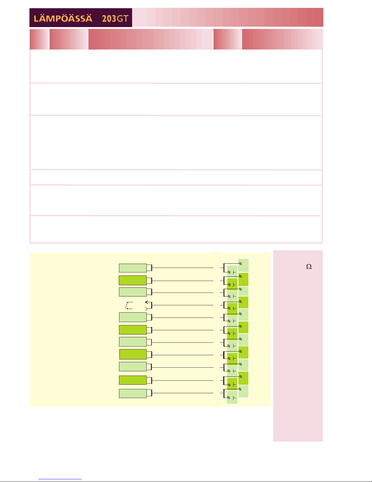
H1 SETTINGS
/
/
=/
H1 Settings
Room temp.
Temp drop
Min. Limit
Max. Limit
Room compens.
=/
=
=
=
21,5
0
15
8
0
Domestic hot water temperature setting.
Because of danger of bacteria, it is recommended that the domestic hot
water temperature is not set below +55°C.
DomHot wat. 55.0°C 5.0...95.0°C
8
KEYWORDS:
H1 Settings
H2 Settings
DHW Settings
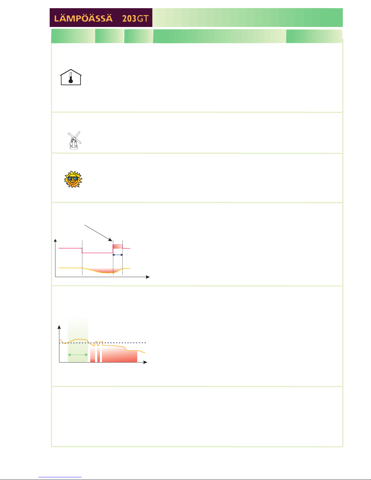
Full effect geothermal heating (see also p. 25-26).
Temperature setting of measurement 9.
the temperature of the accumulator's upper
part (meas. 9) drops below [ ( / 2)].
The compressor stops running when the temperature of the
accumulator's upper part (meas. 9) rises above the [
( / 2)] temperature the temp. of the accumulator's
lower part is high enough (see the AccumLowerMin setting).
Temperature setting of measurement 10.
the temperature of the accumulator's lower
part (meas. 10) drops below the setting.
the temperature of the
accumulator's upper part (meas. 9) rises above the [
( / 2)] temperature the temperature of the
accumulator's lower part (meas. 10) rises above the [
5° C] the temperature of the accumulator's
lower part (meas. 10) rises above the [“AccumLowerMin “
“AccumLowHyst”] temperature
Compressor control has been on for an hour and the temperature of the
accumulator's lower part has not risen a degree the compressor alarm
is active and an attempt has been made to restart the compressor after a
delay time of 5 minutes.
The temperature of the compressor's upper part is below
[ ( /2) ” ]orthe
temperature of the accumulator's upper part (meas.9) is below the
[."]
(This calculation takes into account that the temperature of the controller
indicated H1 supply water temperature is a maximum of 50° C.)
the temperature of
the accumulator's upper part (meas. 9) is above the [
( / 2)] temperature the temp. of the accumulator's
upper part is above the [ ] the
temperature of the accumulator's upper part is above 55° C
A compressor running
command is given when
+
and
A compressor running
command is given when
The compressor stops running when
+
and
+ and
+
The electrical heating resistor switches on if
1.
or
2.
The electrical heating resistor switches off when
and
or
“AccumUpperMin” “AccumUppHyst”
“AccumUpperMin”
“AccumUppHyst”
“AccumLowerMin”
“AccumUpperMin”
“AccumUppHyst”
controller indicated
H1 supply water temp.
“AccumUpperMin” “AccumUppHyst” ElHeatUppHyst”
controller indicated H1 supply water temp El.HeatUppHyst”
“AccumUpperMin”
“AccumUppHyst”
controller indicated H1 supply water temp
-
--
-
-
Accumulator's
upper part min.
temperature
Accumulator's
lower part min
temperature
Additional
hysteresis for
electrical heating
resistor control
"AccumUpperMin"
"AccumLowerMin"
"ElHeatUppHyst"
5...55°C
30...55°C
2...10°C
55°C
45°C
10°C
The same as full effect geothermal heating except that with partial effect
geothermal heating the controller uses a calculated temperature for the
accumulator's upper part (outdoor compensation) in place of the
“AccumUpperMin” setting. (Additional information about outdoor
compensated “Upper part setting” on p. 27)
The same as full effect geothermal heating.
The same as full effect geothermal heating except that in partial effect
geothermal heating the electrical heating resistor and compressor can be
on at the same time. The electrical heating resistor switches on without
an hour's delay when the conditions for electrical heating control have
been met.
Partial effect geothermal heating (see also p. 27-28)
“AccumUpperMin”
“AccumLowerMin”
“El.HeatUppHyst”
5...80°C
30...55°C
2...10°C
55°C
45°C
2°C
Domestic hot water regulating circuit