2
Table of contents
General information
Safety ............................................................................................................................................................................................................ 3
Power supply ......................................................................................................................................................................................... 3
Heat pump domestic hot water ......................................................................................................................................................... 3
Introduction .................................................................................................................................................................................................. 4
Documentation ..................................................................................................................................................................................... 4
Type plate .............................................................................................................................................................................................. 4
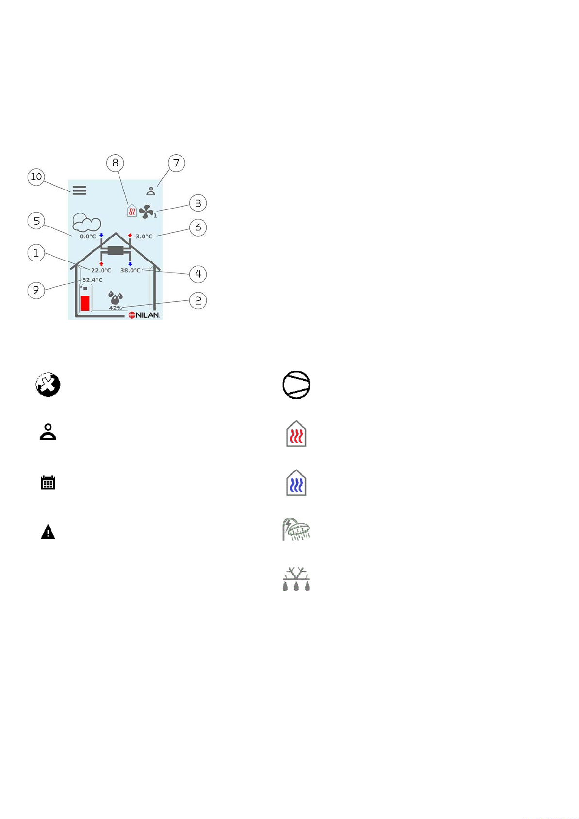
User panel
Functions in the user panel ........................................................................................................................................................................ 5
Main screen elements .......................................................................................................................................................................... 5
Settings options on the main screen ................................................................................................................................................. 6
Warning and alarms ............................................................................................................................................................................. 7
Settings menu overview ..................................................................................................................................................................... 7
Service and maintenance
General information ................................................................................................................................................................................... 8
Regular maintenance ................................................................................................................................................................................. 8
Operation of the ventilation unit ....................................................................................................................................................... 8
Illustration of filter change ................................................................................................................................................................. 9
Service ........................................................................................................................................................................................................10
General cleaning .................................................................................................................................................................................10
Water trap ............................................................................................................................................................................................10
Heat exchanger ...................................................................................................................................................................................10
Checking the sacrificial anode ..........................................................................................................................................................11
Checking the safety valve .................................................................................................................................................................11
Check the air intake and outlet ........................................................................................................................................................11
Check ventilation ducts .....................................................................................................................................................................11
The heat pump ....................................................................................................................................................................................11
User settings
Setting the unit ..........................................................................................................................................................................................12
Turn off the ventilation unit .............................................................................................................................................................12
Operating function .............................................................................................................................................................................12
Alarm ....................................................................................................................................................................................................13
Show data ............................................................................................................................................................................................13
Date/Time ............................................................................................................................................................................................14
Week program .....................................................................................................................................................................................14
Heating of supply air ..........................................................................................................................................................................15
Domestic hot water ............................................................................................................................................................................17
After heating element .......................................................................................................................................................................17
Cooling ..................................................................................................................................................................................................18
Air humidity .........................................................................................................................................................................................19
CO2 Control ..........................................................................................................................................................................................20
Air exchange ........................................................................................................................................................................................20
Air filter ................................................................................................................................................................................................21
Temperature control .........................................................................................................................................................................22
Language ..............................................................................................................................................................................................22
Alarm list
Compact ......................................................................................................................................................................................................23
Alarm list ..............................................................................................................................................................................................23
Troubleshooting
Emergency operation domestic hot water ....................................................................................................................................25
Errors and solutions domestic hot water .......................................................................................................................................26
Technical data
EU/EC Declaration of Conformity ...................................................................................................................................................27
Ecodesign data - Hot water production ..........................................................................................................................................28
Disposal
The environment - part of the solution .................................................................................................................................................29
Ventilation unit ...................................................................................................................................................................................29